The Smell of Molten Projects in the Morning

Ed Nisley's Blog: Shop notes, electronics, firmware, machinery, 3D printing, laser cuttery, and curiosities. Contents: 100% human thinking, 0% AI slop.

Tag: Sherline

Sherline CNC mill

  • Sherline Laser Alignment: Polarizing Filter

    Laser aligner polarizing filter detail
    Laser aligner polarizing filter detail

    A display across the aisle from the CNC Ghetto at Cabin Fever featured a nice Laser Center Edge Finder with their new polarizing attachment. I played with it for a while and decided that, although my crude lashup gave similar results, I just had to have a polarizing filter, too.

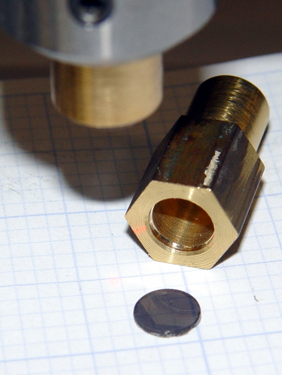
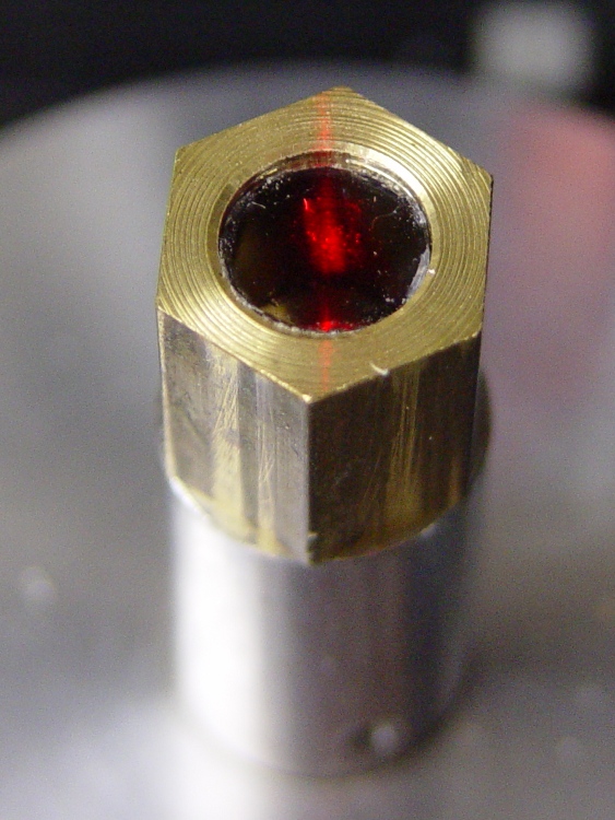
    I’d already made a bushing to fit the top of the spindle bore with a small aperture that aids in lining up the laser, so I just added a small recess for a disk of polarizing film. I have, for reasons that should not require any explanation by now, a lifetime supply of polarizing film…

    Anyhow, the new polarizing filter sits neatly atop the spindle. The main laser beam lights up the middle of the filter, with junk light spilling on the bushing to the front and rear.

    Polarizing film in upper bushing
    Polarizing film in upper bushing

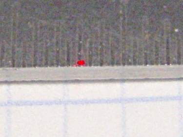
    Getting a good photograph of the spot size poses some problems, but here goes. This is the original, un-attenuated spot on a scale with 0.5 mm divisions: in round numbers, it’s half a millimeter across.

    Normal laser spot size
    Normal laser spot size

    Cross-polarizing the beam produces this attenuated spot on the same scale: it’s 0.25 mm in diameter, maybe a bit less. Call it 10 mils.

    Attenuated laser spot size
    Attenuated laser spot size

    Obviously, what you’re seeing are overexposed more-or-less Gaussian spots, so their diameters aren’t fixed numbers. But at this level, the inaccuracies of my Orc Engineering lens mount are comparable to the spot size, so reducing the spot any further isn’t going to improve the overall positioning accuracy.

    It’s worth noting that the spot size isn’t the same as the positioning accuracy: you can visually align a workpiece mark to less than 1/4 the spot diameter. Claiming 1/10 the diameter would be more brag than fact, at least for me, but somewhere around 2 mils is close. That’s good enough for most of what I do.

    I like it!

  • Improved Sherline Probe Length Switch Repeatability: Selah!

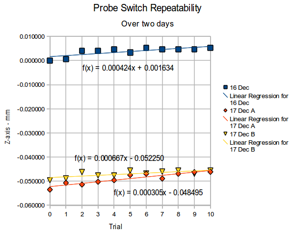
    Re-running that probe length switch test a few weeks later produced these results for three trials over the course of two days.

    Probe Repeatability - Dec 2010
    Probe Repeatability – Dec 2010

    The Z-axis differences are all relative to the first reading on the first day, so this includes whatever Z-axis changes take place without doing anything else on the mill in between the tests. I turned the power off after making the first set of measurements, so the steppers restarted with up to a plus-or-minus one full step offset; that works out to:

    (0.050 inch) * (1 rev / 200 steps) = 0.00025 in = 0.0064 mm
    

    Because EMC2 doesn’t actually know where the stepper is, any uncommanded motion will show up as an offset when the probe switch trips, which is exactly what we see here.

    Two things of interest:

    • The -0.05 mm offset between the two days could well be part of a single step offset
    • Successive probe positions during a single test don’t change by hardly anything at all

    Conclusion: a cheap mechanical switch works just fine and an even cheaper switch was still good enough.

    The dataset looks like this…

    Trial	16 Dec	16 Dec	17 Dec A	17 Dec A	17 Dec B	17 Dec B
    0	25.859616	0.000000	25.806118	-0.053498	25.810032	-0.049584
    1	25.860282	0.000666	25.808900	-0.050716	25.810696	-0.048920
    2	25.863610	0.003994	25.808214	-0.051402	25.813354	-0.046262
    3	25.863610	0.003994	25.809368	-0.050248	25.812028	-0.047588
    4	25.864276	0.004660	25.810032	-0.049584	25.812025	-0.047591
    5	25.862945	0.003329	25.812162	-0.047454	25.814018	-0.045598
    6	25.864941	0.005325	25.812690	-0.046926	25.812719	-0.046897
    7	25.864276	0.004660	25.810696	-0.048920	25.813540	-0.046076
    8	25.864276	0.004660	25.812690	-0.046926	25.814012	-0.045604
    9	25.864276	0.004660	25.813354	-0.046262	25.812690	-0.046926
    10	25.864941	0.005325	25.813477	-0.046139	25.814018	-0.045598
    

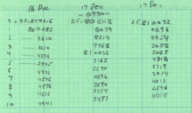
    The raw data, just for completeness…

    Probe test data - Dec 2010
    Probe test data – Dec 2010

    Selah!

    (I’m giving a talk and show-n-telling my Sherline CNC milling machine at Cabin Fever Expo right about now, so having this data readily available seemed prudent. The talk & handouts are there.)

  • Thermocouple Calibration: Isothermal Block

    Verily it is written:

    • The man with one thermometer knoweth the temperature
    • The man with many thermometers knoweth not the temperature
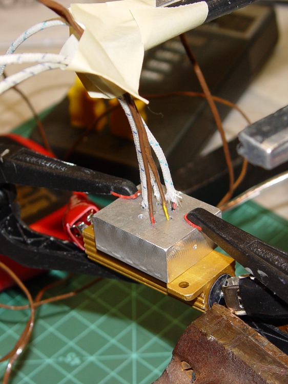
    Drilling the isothermal block
    Drilling the isothermal block

    Given the five thermocouples and their meters shown there, plus the Thing-O-Matic’s thermocouple, I had six different temperatures. They’re close, but we can do better than that.

    The general idea is to put all the thermocouple beads in close proximity so they share the same temperature, record their opinions to various temperatures, then figure out an equation that adjusts their disparate opinions to reflect consensus reality.

    I cranked out an isothermal block on the Sherline mill, using EMC2’s exceedingly handy polar coordinate notation to get a nice hexagon. Touch off XYZ=0 at the middle of the block, then center-drill and drill:

    G0 Z3
    G0 @5 ^0
    G83 Z-5 R3 Q1 F100
    G0 ^60
    G83 Z-5 R3 Q1 F100
    G0 ^120
    ... etc ..
    

    For lack of anything better, 3000 rpm with a drill matching the ID of the brass tubes, plus dripping cutting fluid as needed.

    Thermocouples in block
    Thermocouples in block

    I used a 6 Ω 50 W resistor (the adult version of the resistors on the Thing-O-Matic / MK5 head) as a heat source, clamping the block to the resistors with plastic clamps to provide mechanical force and thermal isolation. Good idea, bad implementation: as you’ll see, those little red tips melt at a rather low temperature.

    The TOM thermocouple bead will fit into the empty hole.

    Next step: numbers!

  • Cabin Fever Tchotchke: Engraved Dog Tag

    Once again I’m planning to attend the Cabin Fever Expo in York; my shop assistant says this year she won’t barf in the kitchen sink Thursday evening just before bedtime…

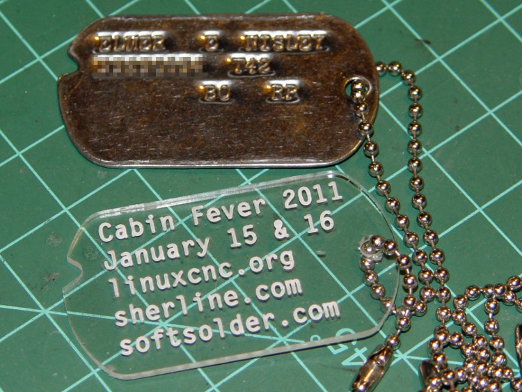
    If I’m going to haul a Sherline CNC setup that far and spend all day talking machining, I must have some tchotchkes / swag to talk about. We figured a small plastic dog tag with relevant URLs would be appropriate.

    Cabin Fever Dog Tag
    Cabin Fever Dog Tag

    I modeled the tag after my father’s WWII tag, including the mysterious notch. The rounded ends actually have three curves: two small fairing arcs blend the sides into the end cap.

    The G-Code routine figures out all the coordinates and suchlike from some basic physical measurements & guesstimates, so tweaking the geometery is pretty straightforward. There was a blizzard going on while I wrote it: a fine day to spend indoors hacking code.

    My assistant fired up Inkscape, laid out the text, figured out how to coerce G-Code out of Inkscape using the cnc-club.ru extension, then aligned it properly with the center of the chain hole as the origin on the right side. My routine calls the text G-Code file as a subroutine.

    The extension’s header and footer files wrap EMC2’s SUB / ENDSUB syntactic sugar around the main file. The default files include an M2 that kills off the program; took a while to track that one down.

    The header file:

    O<dogtagtext> SUB
    

    And the matching footer file:

    O<dogtagtext> ENDSUB
    

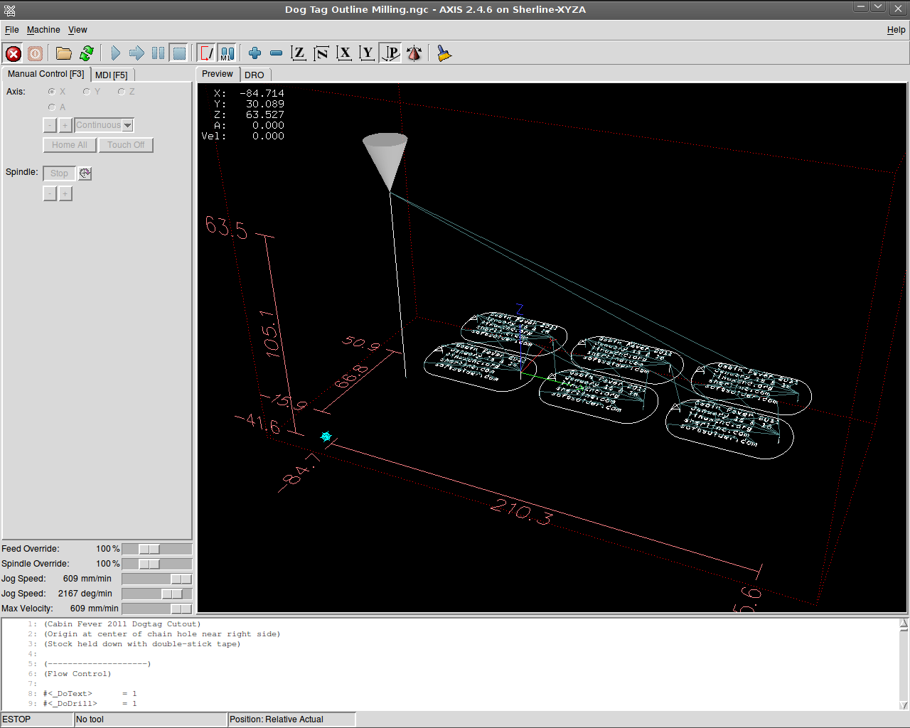
    The Inkscape-to-gcode instructions come out with absolute coordinates relative to the origin you define when you create the layout. The nested loops in my wrapper slap a G55 coordinate offset atop each label in turn, then call the subroutine.

    The result is pretty slick:

    Screenshot: AXIS Dog Tags
    Screenshot: AXIS Dog Tags

    I carved out that proof-of-concept label atop double-sided adhesive tape, but peeling off the goo is a real pain; a 2×3 array will be much worse. I’d rather do that than figure out how to clamp the fool things to the sacrificial plate, though.

    The engraving is 0.2 mm deep with a Dremel 30 degree tool. My shop assistant describes it as “disturbing” the acrylic, not actually engraving a channel. This isn’t entirely a Bad Thing, as the font isn’t quite a stick font and the outline of each character mushes together. We must fiddle with the font a bit more; she favors a boldified OCR-A look.

    Some lessons:

    • The Kate G-Code syntax highlighter isn’t down with EMC2’s dialect
    • Be very sure you touch off the workpiece origin in G54, not G55
    • Xylene doesn’t bother acrylic and works fine on tape adhesive
    • Symlinks aimed across an NFS link work fine in ~/emc2/nc_files/
    • That 2×3 array may be too big for the Sherline’s tooling plate
    • Tool length probing FTW!

    The G-Code:

    (Cabin Fever 2011 Dogtag)
    (Ed Nisley - KE4ZNU - December 2010)
    (Origin at center of chain hole near right side)
    (Stock held down with double-stick tape)
    
    (--------------------)
    (Flow Control)
    
    #<_DoText>      = 1
    #<_DoDrill>     = 1
    #<_DoMill>      = 1
    
    ( Sizes and Shapes)
    
    (-- Tag array layout)
    
    #<_NumTagsX>    = 3                         (number of tags along X axis)
    #<_NumTagsY>    = 2                         ( ... Y axis)
    
    #<_TagSpaceX>   = 60                        (center-to-center along X axis)
    #<_TagSpaceY>   = 35                        ( ... Y axis)
    
    (-- Tag Dimensions)
    
    #<_TagSizeX>    = 50.8                      (2.0 inches in WWII!)
    #<_TagSizeY>    = 28.6                      (1-1/8 inches)
    #<_TagSizeZ>    = 2.0
    
    #<_HoleOffsetX> = 4.0                       (hole center to right-side tag edge)
    
    #<_NotchSizeX>      = 3.5                   (locating notch depth from far left edge)
    #<_NotchCtrY>       = 5.0                   (locating notch from Y=0)
    
    #<_NotchAngleBot>   = 30                    (lower angle in notch)
    #<_NotchAngleTop>   = 45                    (upper angle in notch)
    
    (-- Fairing Curve Dimensions as offsets from end arc center)
    
    #<_EndFairR>    = [0.68 * #<_TagSizeY>]
    #<_CornerFairR> = [0.25 * #<_TagSizeY>]
    
    #<_PCRadius>    = [#<_EndFairR> - #<_CornerFairR>]
    #<_PCY>         = [[#<_TagSizeY> / 2] - #<_CornerFairR>]
    #<_PCTheta>     = ASIN [#<_PCY> / #<_PCRadius>]
    #<_PCX>         = [#<_PCRadius> * COS [#<_PCTheta>]]
    
    #<_P1Y>         = [#<_TagSizeY> / 2]                    (top / bottom endpoint)
    #<_P1X>         = #<_PCX>
    
    #<_P2X>         = [#<_EndFairR> * COS [#<_PCTheta>]]
    #<_P2Y>         = [#<_EndFairR> * SIN [#<_PCTheta>]]
    
    (-- Tooling)
    
    #<_TraverseZ>   = 1.0                       (safe clearance above workpiece)
    
    #<_DrillDia>    = 3.2                       (drill for hole and notch)
    #<_DrillNum>    = 1                         ( ... tool number)
    #<_DrillRadius> = [#<_DrillDia> / 2]
    #<_DrillFeed>   = 200                       (drill feed for holes)
    #<_DrillRPM>    = 3000
    
    #<_MillDia>     = 3.2                       (mill for outline)
    #<_MillNum>     = 1                         ( ... tool number)
    #<_MillRadius> = [#<_MillDia> / 2]
    #<_MillFeed>    = 150                       (tool feed for outlines)
    #<_MillRPM>     = 5000
    
    #<_TextDia>     = 0.1                       (engraving tool)
    #<_TextNum>     = 1
    #<_TextFeed>    = 600                       (tool feed for engraving)
    #<_TextRPM>     = 10000
    
    (-- Useful calculated values)
    
    #<_TagRightX>   = #<_HoleOffsetX>           (extreme limits of tag in X)
    #<_TagLeftX>    = [#<_TagRightX> - #<_TagSizeX>]
    
    #<_EndFairRtX>  = [#<_TagRightX> - #<_EndFairR>]
    #<_EndFairLfX>  = [#<_TagLeftX> + #<_EndFairR>]
    
    #<_NotchCtrX>   = [#<_TagLeftX> + #<_NotchSizeX> - #<_DrillRadius>]
    
    (--------------------)
    (--------------------)
    ( Initialize first tool length at probe switch)
    (    Assumes G59.3 is still in machine units, returns in G54)
    ( ** Must set these constants to match G20 / G21 condition!)
    
    #<_Probe_Speed>     = 400            (set for something sensible in mm or inch)
    #<_Probe_Retract>   =   1            (ditto)
    
    O<Probe_Tool> SUB
    
    G49                     (clear tool length compensation)
    G30                     (move above probe switch)
    G59.3                   (coord system 9)
    
    G38.2 Z0 F#<_Probe_Speed>           (trip switch on the way down)
    
    G0 Z[#5063 + #<_Probe_Retract>]     (back off the switch)
    
    G38.2 Z0 F[#<_Probe_Speed> / 10]    (trip switch slowly)
    
    #<_ToolZ> = #5063                    (save new tool length)
    
    G43.1 Z[#<_ToolZ> - #<_ToolRefZ>]    (set new length)
    
    G54                     (coord system 0)
    G30                     (return to safe level)
    
    O<Probe_Tool> ENDSUB
    
    (-------------------)
    (-- Initialize first tool length at probe switch)
    
    O<Probe_Init> SUB
    
    #<_ToolRefZ> = 0.0      (set up for first call)
    
    O<Probe_Tool> CALL
    
    #<_ToolRefZ> = #5063    (save trip point)
    
    G43.1 Z0                (tool entered at Z=0, so set it there)
    
    O<Probe_Init> ENDSUB
    
    (--------------------)
    (Start machining)
    
    G40 G49 G54 G80 G90 G94 G97 G98     (reset many things)
    
    G21                                 (metric!)
    
    (msg,Verify G30.1 position in G54 above tool change switch)
    M0
    (msg,Verify XYZ=0 touched off at left front tag hole center on surface)
    M0
    
    O<Probe_Init> CALL
    T0 M6                           (clear the probe tool)
    
    (-- Engrave Text)
    
    O<DoText> IF [#<_DoText>]
    
    (msg,Insert engraving tool)
    T#<_TextNum> M6         (load engraving tool)
    O<Probe_Tool> CALL
    
    F#<_TextFeed>
    S#<_TextRPM>
    
    (debug,Set spindle to #<_TextRPM>)
    M0
    
    G0 X0 Y0                (get safely to first tag)
    G0 Z#<_TraverseZ>       (to working level)
    
    G10 L20 P2 X0 Y0 Z#<_TraverseZ>         (set G55 origin to 0,0 at this point)
    G55                                     (activate G55 coordinates)
    
    O3000 REPEAT [#<_NumTagsX>]
    
    O3100 REPEAT [#<_NumTagsY>]
    
    O<dogtagtext> CALL
    
    G0 X0 Y0
    G10 L20 P2 Y[0 - #<_TagSpaceY>]         (set Y orgin relative to next tag in +Y direction)
    
    O3100 ENDREPEAT
    
    G10 L20 P2 X[0 - #<_TagSpaceX>] Y[[#<_NumTagsY> - 1] * #<_TagSpaceY>] (next to +X, Y to front)
    
    O3000 ENDREPEAT
    
    G54                                     (bail out of G55 coordinates)
    
    (-- Drill holes)
    
    O<DoDrill> IF [#<_DoDrill>]
    
    T0 M6
    (msg,Insert drill)
    T#<_DrillNum> M6
    O<Probe_Tool> CALL
    
    F#<_DrillFeed>
    S#<_DrillRPM>
    
    #<_DrillZ> = [0 - #<_TagSizeZ> - #<_DrillRadius>]
    
    (debug,Set spindle to #<_DrillRPM>)
    M0
    
    G0 X0 Y0                (get safely to first tag)
    G0 Z#<_TraverseZ>       (to working level)
    
    #<IndexX> = 0
    O1000 DO
    
    #<IndexY> = 0
    O1100 DO
    
    #<TagOriginX> = [#<IndexX> * #<_TagSpaceX>]
    #<TagOriginY> = [#<IndexY> * #<_TagSpaceY>]
    
    G81 X#<TagOriginX> Y#<TagOriginY> Z#<_DrillZ> R#<_TraverseZ>
    G81 X[#<TagOriginX> + #<_NotchCtrX>] Y[#<TagOriginY> + #<_NotchCtrY>] Z#<_DrillZ> R#<_TraverseZ>
    
    #<IndexY> = [#<IndexY> + 1]
    O1100 WHILE [#<IndexY> LT #<_NumTagsY>]
    
    #<IndexX> = [#<IndexX> + 1]
    O1000 WHILE [#<IndexX> LT #<_NumTagsX>]
    
    G30     (go home)
    
    O<DoDrill> ENDIF
    
    (-- Machine outlines)
    
    O<DoMill> IF [#<_DoMill>]
    
    T0 M6                   (eject drill)
    (msg,Insert end mill)
    T#<_MillNum> M6         (load mill)
    O<Probe_Tool> CALL
    
    F#<_MillFeed>
    S#<_MillRPM>
    
    (debug,Set spindle to #<_MillRPM>)
    M0
    
    G0 X0 Y0                (get safely to first tag)
    G0 Z#<_TraverseZ>       (to working level)
    
    G10 L20 P2 X0 Y0 Z#<_TraverseZ>         (set G55 origin to 0,0 at this point)
    G55                                     (activate G55 coordinates)
    
    O2000 REPEAT [#<_NumTagsX>]
    
    O2100 REPEAT [#<_NumTagsY>]
    
    G0 X[#<_NotchCtrX>] Y[#<_NotchCtrY>]     (get to center of notch hole)
    G0 Z[0 - #<_TagSizeZ>]                      (down to cutting level)
    
    G91                                         (relative coordinate for notch cutting)
    G1 X[0 - #<_NotchSizeX>] Y[0 -  #<_NotchSizeX> * TAN [#<_NotchAngleBot>]]
    G1 X[0 + #<_NotchSizeX>] Y[0 +  #<_NotchSizeX> * TAN [#<_NotchAngleBot>]]
    G1 X[0 - #<_NotchSizeX>] Y[0 +  #<_NotchSizeX> * TAN [#<_NotchAngleTop>]]
    G90                                         (back to abs coords)
    
    G42.1 D#<_MillDia>                          (cutter comp to right)
    G1 X[#<_TagLeftX>] Y0                       (comp entry move to tip of left endcap)
    
    G3 X[#<_EndFairLfX> - #<_P2X>] Y[0 - #<_P2Y>] I[#<_EndFairR>] J0    (left endcap front half)
    
    G3 X[#<_EndFairLfX> - #<_P1X>] Y[0 - #<_P1Y>] I[#<_P2X> - #<_PCX>] J[#<_P2Y> - #<_PCY>]
    
    G1 X[#<_EndFairRtX> + #<_P1X>]                                      (front edge)
    
    G3 X[#<_EndFairRtX> + #<_P2X>] Y[0 - #<_P2Y>] I0 J[#<_CornerFairR>]
    
    G3 X[#<_EndFairRtX> + #<_P2X>] Y[#<_P2Y>] I[0 - #<_P2X>] J[#<_P2Y>]    (right endcap)
    
    G3 X[#<_EndFairRtX> + #<_P1X>] Y[#<_P1Y>] I[#<_PCX> - #<_P2X>] J[#<_PCY> - #<_P2Y>]
    
    G1 X[#<_EndFairLfX> - #<_P1X>]                                      (rear edge)
    
    G3 X[#<_EndFairLfX> - #<_P2X>] Y[#<_P2Y>] I0 J[0 - #<_CornerFairR>]
    
    G3 X[#<_EndFairLfX> - #<_P2X>] Y[0 - #<_P2Y>] I[#<_P2X>] J[0 - #<_P2Y>]    (left endcap complete)
    
    G0 Z#<_TraverseZ>
    
    G40
    
    G0 X0 Y0
    G10 L20 P2 Y[0 - #<_TagSpaceY>]         (set Y orgin relative to next tag in +Y direction)
    
    O2100 ENDREPEAT
    
    G10 L20 P2 X[0 - #<_TagSpaceX>] Y[[#<_NumTagsY> - 1] * #<_TagSpaceY>] (next to +X, Y to front)
    
    O2000 ENDREPEAT
    
    G54                                     (bail out of G55 coordinates)
    
    G30         (go home)
    
    O<DoMill> ENDIF
    
    M2


    The doodles leading to the equations:

    Dog Tag Geometry Doodles
    Dog Tag Geometry Doodles

    We’ll see you there!

  • Recycled Heatsink: Hole Plugs

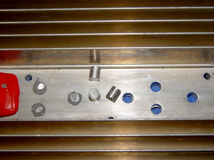
    I actually did get around to plugging the holes directly under the power resistors on those heatsinks, even though we all know it makes absolutely no difference whatsoever.

    Heatsink hole plugs
    Heatsink hole plugs

    Start with some 5/16-inch aluminum rod, face and center-drill one end, turn down about two inches to a scant 0.200 inch diameter, saw off a stub on the end.

    Grab the stub in the 3-jaw Sherline chuck clamped to the mill table and slice off 0.240 inch slugs using a teeny slitting saw and manual CNC.

    No pix of the setup, for reasons that made sense at the time, but that project gives you the general idea.

    Repeat three times to get 3 x 6 = 18 slugs, plus a few spares.

    Clean out the heatsink holes, clamp a bar (covered with tape) on the flat side, butter up the holes & slugs with JB Weld epoxy, squish ’em in place, scrape off the excess epoxy after a few hours.

    Actually, this was a thinly veiled excuse to get my shop assistant some Quality Shop Time on the lathe and CNC mill. Wouldn’t you do the same?

  • From Peanuts to Chips: EMC2 on the Atom

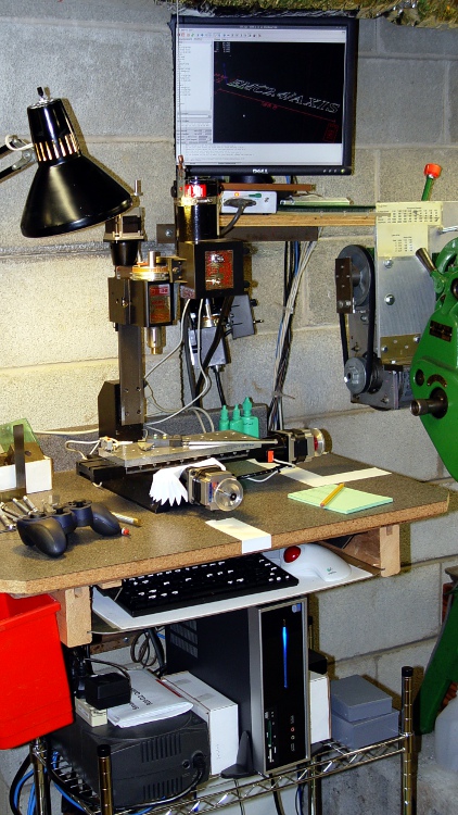
    Sherline CNC with Foxconn D520 Atom
    Sherline CNC with Foxconn D520 Atom

    Before I forget, here’s how one gets from packing peanuts to a running EMC2 installation:

    The hardware:

    The PC won’t need a CD after it’s up and running, but it’s easiest to boot/install from a CD. Get a random SATA CD drive from eBay or, more usefully, a USB-to-SATA/IDE converter, harvest an IDE CD drive from a old donor box, plug it into the Foxconn box, and tweak the BIOS to boot from that USB device.

    Install Ubuntu 10.04 (not the current 10.10) from CD. I use the mini-iso CD (link to Overview), which has the advantage of fetching the current version of everything from the Ubuntu site. You can putz around making a bootable USB image, which is cute, but the USB-to-IDE drive adapter will come in handy for other things.

    Toward the end of the installation you get a list of configurations and packages to install. Pick Ubuntu desktop, down near the bottom of the list. Include SSH server if you want to do remote maintenance.

    Install / tweak / twiddle to set up some comfort items:

    • NFS shares to the file server holding my CNC files
    • Desktop sharing so I can dry-run from a warmer chair
    • Screen backdrop on file server to show network is running
    • Browser plugins & so forth

    When that’s done, aim Firefox at the EMC2 wiki, and follow the instructions to download & run the script that installs EMC2.

    Then devote one of the CPU cores to the real-time kernel, although the new GRUB2 bootloader is less tweak-friendly. Reboot, select that kernel, and away you go.

    Run the EMC2 Latency Test to be sure everything is OK.

    Run the StepConf Wizard to generate a config file suitable for the new machinery.

    This set of hints & tips may be helpful for new-to-Ubuntu machinists.

    Lest all this seem like a lot of hocus pocus, remember that you’re
    becoming a system integrator with your fingers on all the knobs and
    buttons normally hidden behind the “Do Not Open: No User Serviceable Parts Inside” covers.

    You could, of course, pay somebody to do this for you… [grin]

  • Atom D520: Config Files for Smoother Sherline Stepping

    The dual-core-ness of the D520, as set up there, allows a distinct improvement in the EMC2 BASE_PERIOD setting, which is exactly why I undertook this adventure.

    The 100 µs period I used on the Dell Dimension 4550 ensured the occasional long-latency burps wouldn’t cause much trouble… and they didn’t. The setup used the HAL step generator’s ability to supply a single pulse within one base period, so the maximum stepping rate was 1/100 µs = 10 k steps / second.

    However, that also determines the granularity of speed changes, so the controller can only drive the motors at multiples of the basic 100 µs without interpolating. For example, the four fastest step rates are:

    • 1/100 µs = 10 k step/sec
    • 1/200 µs =5 k step/sec
    • 1/300 µs = 3.3 k step/sec
    • 1/400 µs = 2.5 k step/sec

    The motors have 200 major steps / revolution and run in quarter-step mode: 800 microsteps / revolution. The axes have 20 turn-per-inch leadscrews, thus requiring 16 k step pulses per inch of travel.

    That means the corresponding traverse speeds are (step/sec) / (step/inch):

    • 10 k step/sec -> 0.625 in/sec = 37 in/min
    • 5 k step/sec -> 0.313 in/sec = 18.75 in/min
    • 3.3 k step/sec -> 0.206 in/sec = 12.37 in/min
    • 2.5 k step/sec -> 0.156 in/sec = 9.37 in/min

    Those are fairly large jumps between the speeds, which means the motor acceleration when the step rate changes is fairly high. HAL interpolates by bunching groups of pulses, but higher resolution is better.

    The Atom CPU has latencies under 10 µs, with no large burps that I’ve seen so far, so I set the BASE_PERIOD to 50 µs. However, that required changing the HAL step generator to produce a pulse during two successive periods (one high, one low) to keep the pulses wide enough for the motor controller. That means the highest step rate is still 10 k steps/sec and the top speed is still 37 inch/min.

    However, HAL can now adjust the period in smaller increments with lower acceleration between the jumps. The four fastest rates are now:

    • 1/100 µs = 10 k step/sec -> 0.625 in/sec = 37 in/min
    • 1/150 µs =6.7 k step/sec -> 0.417 in/sec = 25 in/min
    • 1/200 µs = 5 k step/sec -> 0.313 in/sec = 18.75 in/min
    • 1/250 µs = 4 k step/sec -> 0.250 in/sec = 15 in/min

    A stock Sherline CNC milling machine is rated for 22 inch/min (0.37 inch/sec) rapid motion on all three axes. That means the maximum step rate is

    • (0.37 inch/sec) * (16 k step/in) = 5.9 kHz

    Quite some years ago, I rebuilt my Sherline controller box to reduce its electrical and acoustic noise, then did a clean-room reimplementation of the firmware in the PIC microcontrollers. After the dust settled, my firmware could handle 8 k steps / sec, which works out to 0.5 in/sec = 30 in/min.

    That turns out to be slightly more aggressive than the whole lashup can tolerate; I can hear the motors take occasional hits as they miss the odd step at 30 inch/min.

    So I set the overall MAX_LINEAR_VELOCITY = 0.400 inch/sec = 24 inch/min, which is also the MAX_VELOCITY for both X and Y. The Z axis, as always, is happier with a bit slower top speed: 0.333 inch/sec = 20 inch/min. The maximum step rate is 0.4 x 16 k = 6.4 kHz, comfortably under the controller’s upper limit.

    The MAX_ACCELERATION for X and Y = 5.0 in/sec2, with Z at 3.0. STEPGEN_MAXACCEL for each axis is twice that; I have each axis set for a few mils of backlash compensation.

    With all that in mind, the changed configuration files look like this, with the others remaining as described there.

    Sherline.hal, with the new stepgen pulse specs

    # Generated by stepconf at Sat Aug 23 12:10:22 2008
    # If you make changes to this file, they will be
    # overwritten when you run stepconf again
    loadrt trivkins
    loadrt [EMCMOT]EMCMOT base_period_nsec=[EMCMOT]BASE_PERIOD servo_period_nsec=[EMCMOT]SERVO_PERIOD traj_period_nsec=[EMCMOT]SERVO_PERIOD key=[EMCMOT]SHMEM_KEY num_joints=[TRAJ]AXES
    loadrt probe_parport
    loadrt hal_parport cfg="0x378 out"
    setp parport.0.reset-time 60000
    loadrt stepgen step_type=0,0,0,0
    loadrt pwmgen output_type=0
    
    addf parport.0.read base-thread
    addf stepgen.make-pulses base-thread
    addf pwmgen.make-pulses base-thread
    addf parport.0.write base-thread
    addf parport.0.reset base-thread
    
    addf stepgen.capture-position servo-thread
    addf motion-command-handler servo-thread
    addf motion-controller servo-thread
    addf stepgen.update-freq servo-thread
    addf pwmgen.update servo-thread
    
    net spindle-cmd <= motion.spindle-speed-out => pwmgen.0.value
    net spindle-enable <= motion.spindle-on => pwmgen.0.enable
    net spindle-pwm <= pwmgen.0.pwm
    setp pwmgen.0.pwm-freq 100.0
    setp pwmgen.0.scale 1166.66666667
    setp pwmgen.0.offset 0.114285714286
    setp pwmgen.0.dither-pwm true
    net spindle-cw <= motion.spindle-forward
    
    net estop-out => parport.0.pin-01-out
    net xdir => parport.0.pin-02-out
    net xstep => parport.0.pin-03-out
    setp parport.0.pin-03-out-reset 0
    setp parport.0.pin-04-out-invert 1
    net ydir => parport.0.pin-04-out
    net ystep => parport.0.pin-05-out
    setp parport.0.pin-05-out-reset 0
    setp parport.0.pin-06-out-invert 1
    net zdir => parport.0.pin-06-out
    net zstep => parport.0.pin-07-out
    setp parport.0.pin-07-out-reset 0
    net adir => parport.0.pin-08-out
    net astep => parport.0.pin-09-out
    setp parport.0.pin-09-out-reset 0
    net spindle-cw => parport.0.pin-14-out
    net spindle-pwm => parport.0.pin-16-out
    net xenable => parport.0.pin-17-out
    
    setp stepgen.0.position-scale [AXIS_0]SCALE
    setp stepgen.0.steplen 1
    setp stepgen.0.stepspace 1
    setp stepgen.0.dirhold 60000
    setp stepgen.0.dirsetup 60000
    setp stepgen.0.maxaccel [AXIS_0]STEPGEN_MAXACCEL
    net xpos-cmd axis.0.motor-pos-cmd => stepgen.0.position-cmd
    net xpos-fb stepgen.0.position-fb => axis.0.motor-pos-fb
    net xstep <= stepgen.0.step
    net xdir <= stepgen.0.dir
    net xenable axis.0.amp-enable-out => stepgen.0.enable
    
    setp stepgen.1.position-scale [AXIS_1]SCALE
    setp stepgen.1.steplen 1
    setp stepgen.1.stepspace 1
    setp stepgen.1.dirhold 60000
    setp stepgen.1.dirsetup 60000
    setp stepgen.1.maxaccel [AXIS_1]STEPGEN_MAXACCEL
    net ypos-cmd axis.1.motor-pos-cmd => stepgen.1.position-cmd
    net ypos-fb stepgen.1.position-fb => axis.1.motor-pos-fb
    net ystep <= stepgen.1.step
    net ydir <= stepgen.1.dir
    net yenable axis.1.amp-enable-out => stepgen.1.enable
    
    setp stepgen.2.position-scale [AXIS_2]SCALE
    setp stepgen.2.steplen 1
    setp stepgen.2.stepspace 1
    setp stepgen.2.dirhold 60000
    setp stepgen.2.dirsetup 60000
    setp stepgen.2.maxaccel [AXIS_2]STEPGEN_MAXACCEL
    net zpos-cmd axis.2.motor-pos-cmd => stepgen.2.position-cmd
    net zpos-fb stepgen.2.position-fb => axis.2.motor-pos-fb
    net zstep <= stepgen.2.step
    net zdir <= stepgen.2.dir
    net zenable axis.2.amp-enable-out => stepgen.2.enable
    
    setp stepgen.3.position-scale [AXIS_3]SCALE
    setp stepgen.3.steplen 1
    setp stepgen.3.stepspace 1
    setp stepgen.3.dirhold 60000
    setp stepgen.3.dirsetup 60000
    setp stepgen.3.maxaccel [AXIS_3]STEPGEN_MAXACCEL
    net apos-cmd axis.3.motor-pos-cmd => stepgen.3.position-cmd
    net apos-fb stepgen.3.position-fb => axis.3.motor-pos-fb
    net astep <= stepgen.3.step
    net adir <= stepgen.3.dir
    net aenable axis.3.amp-enable-out => stepgen.3.enable
    
    net estop-out <= iocontrol.0.user-enable-out
    net estop-out => iocontrol.0.emc-enable-in
    
    loadusr -W hal_manualtoolchange
    net tool-change iocontrol.0.tool-change => hal_manualtoolchange.change
    net tool-changed iocontrol.0.tool-changed <= hal_manualtoolchange.changed
    net tool-number iocontrol.0.tool-prep-number => hal_manualtoolchange.number
    net tool-prepare-loopback iocontrol.0.tool-prepare => iocontrol.0.tool-prepared
    

    Sherline.ini, with new periods, speeds, and accelerations

    # Ed Nisley - KE4ZNU
    # Just do not run stepconf ever again...
    
    [EMC]
    MACHINE = Sherline-XYZA
    DEBUG = 0
    RS274NGC_STARTUP_CODE = G21 G40 G49 G54 G80 G90 G92.1 G94 G97 G98
    
    [DISPLAY]
    DISPLAY = axis
    EDITOR = gedit
    GEOMETRY = AXYZ
    POSITION_OFFSET = RELATIVE
    POSITION_FEEDBACK = ACTUAL
    MAX_FEED_OVERRIDE = 3.0
    INTRO_GRAPHIC = /home/ed/emc2/configs/Sherline-XYZA/Sherline.gif
    INTRO_TIME = 3
    #PROGRAM_PREFIX = /mnt/bulkdata/
    PROGRAM_PREFIX = ~/emc2/nc_files
    #INCREMENTS = .1in .05in .01in .005in .001in .0005in .0001in
    INCREMENTS = 10 mm, 1 mm, 0.1 mm, 90 deg, 45 deg, 10 deg
    
    [FILTER]
    PROGRAM_EXTENSION = .py Python Script
    py = python
    
    [TASK]
    TASK = milltask
    CYCLE_TIME = 0.010
    
    [RS274NGC]
    PARAMETER_FILE = emc.var
    
    [EMCMOT]
    EMCMOT = motmod
    SHMEM_KEY = 111
    COMM_TIMEOUT = 1.0
    COMM_WAIT = 0.010
    BASE_PERIOD = 50000
    SERVO_PERIOD = 1000000
    
    [HAL]
    HALUI=halui
    HALFILE = Sherline.hal
    HALFILE = custom.hal
    HALFILE = Logitech_Gamepad.hal
    POSTGUI_HALFILE = custom_postgui.hal
    
    [TRAJ]
    AXES = 4
    COORDINATES = X Y Z A
    MAX_ANGULAR_VELOCITY = 45.00
    DEFAULT_ANGULAR_VELOCITY = 36.0
    LINEAR_UNITS = inch
    ANGULAR_UNITS = degree
    CYCLE_TIME = 0.010
    DEFAULT_VELOCITY = 0.400
    MAX_LINEAR_VELOCITY = 0.400
    POSITION_FILE =	lastposition.txt
    NO_FORCE_HOMING = 1
    
    [EMCIO]
    EMCIO = io
    CYCLE_TIME = 0.100
    TOOL_TABLE = Sherline.tbl
    TOOL_CHANGE_AT_G30 = 1
    
    [AXIS_0]
    TYPE = LINEAR
    MAX_VELOCITY = 0.400
    MAX_ACCELERATION = 5.0
    STEPGEN_MAXACCEL = 10.0
    SCALE = 16000.0
    FERROR = 0.05
    MIN_FERROR = 0.01
    MIN_LIMIT = -1.0
    MAX_LIMIT = 9.5
    BACKLASH = 0.003
    HOME_IS_SHARED = 1
    HOME_SEQUENCE = 2
    HOME_SEARCH_VEL = 0.3
    HOME_LATCH_VEL = 0.016
    HOME_FINAL_VEL = 0.4
    HOME_OFFSET = 9.1
    HOME = 4.5
    
    [AXIS_1]
    TYPE = LINEAR
    MAX_VELOCITY = 0.400
    MAX_ACCELERATION = 5.0
    STEPGEN_MAXACCEL = 10.0
    SCALE = 16000.0
    FERROR = 0.05
    MIN_FERROR = 0.01
    MIN_LIMIT = -0.5
    MAX_LIMIT = 4.90
    BACKLASH = 0.003
    HOME_IS_SHARED = 1
    HOME_SEQUENCE = 1
    HOME_SEARCH_VEL = -0.3
    HOME_LATCH_VEL = -0.016
    HOME_FINAL_VEL = 0.4
    HOME_OFFSET = 0.0
    HOME = 4.0
    
    [AXIS_2]
    TYPE = LINEAR
    MAX_VELOCITY = 0.333
    MAX_ACCELERATION = 3.0
    STEPGEN_MAXACCEL = 6.0
    SCALE = 16000.0
    FERROR = 0.05
    MIN_FERROR = 0.01
    MIN_LIMIT = 0.0
    MAX_LIMIT = 6.930
    BACKLASH = 0.005
    HOME_IS_SHARED = 1
    HOME_SEQUENCE = 0
    HOME_SEARCH_VEL = 0.200
    HOME_LATCH_VEL = 0.016
    HOME_FINAL_VEL = 0.3
    HOME_OFFSET = 6.93
    HOME = 6.5
    
    [AXIS_3]
    TYPE = ANGULAR
    ###WRAPPED_ROTARY = 1
    MAX_VELOCITY = 40.0
    MAX_ACCELERATION = 250.0
    STEPGEN_MAXACCEL = 275.0
    SCALE = 160.0
    FERROR = 1
    MIN_FERROR = .25
    MIN_LIMIT = -999999999.9
    MAX_LIMIT =  999999999.9
    HOME_SEARCH_VEL = 0
    HOME_LATCH_VEL = 0
    HOME = 0.0