The Smell of Molten Projects in the Morning

Ed Nisley's Blog: Shop notes, electronics, firmware, machinery, 3D printing, laser cuttery, and curiosities. Contents: 100% human thinking, 0% AI slop.

Tag: Sherline

Sherline CNC mill

  • Stepper Dynamometer Mechanics

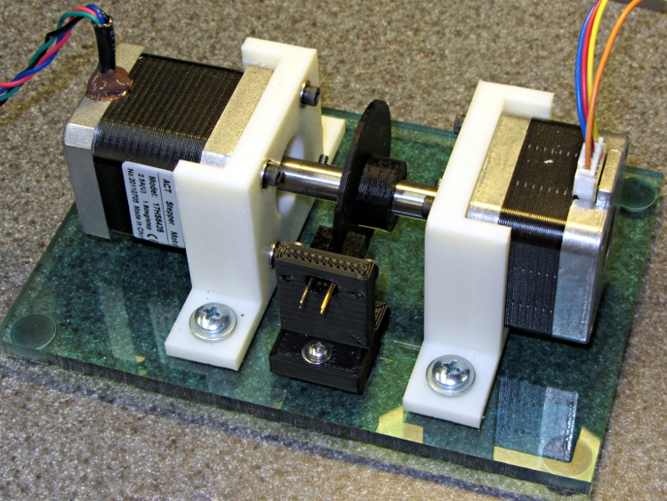
    Combine two of those mounts with one of those couplers, add two NEMA 17 steppers (the one on the right is that one), slide a baseplate underneath, sprinkle with various screws, and shazam you get a stepper motor dynamometer:

    Stepper Dynamometer
    Stepper Dynamometer

    The baseplate puts the mounts 65 mm apart on the 10-32 screw centers, which is entirely a function of the coupler length, and is easy with manual CNC on the Sherline.

    Changing the motors is straightforward: loosen coupler setscrew, remove base screws, slide motor away from coupler, remove mount screws. Won’t happen that often, methinks.

    The general idea is to drive one stepper with a known current, apply a known resistive load to the other motor’s windings, and then plot torque vs. speed. It won’t be quite that simple, of course, but should produce some interesting data.


  • Stepper Motor Shaft Coupler

    This simple cylinder connects two NEMA 17 stepper motors together:

    Stepper Shaft Coupler
    Stepper Shaft Coupler

    It’s quick-and-dirty:

    • Cut 2+ inches of 0.375 drill rod, face both ends
    • Drill #8 = 0.199 inch = 5.06 mm (because #9 = 0.196 inch = 4.98 mm is a bit too snug)
    • Cross-drill #41 in the Sherline (because #43 makes for stiff tapping)
    • Tap 4-40 for the setscrews
    • File off rough edges, run #8 drill through the bore to clean out tapping chips &c

    Now, you probably don’t want to do this in real life, because you want a coupler with a bit of compliance to soak up the inevitable misalignment and dampen the mechanical resonances.

  • Why Manual CNC Is A Bad Idea

    Crushed tool length probe switch
    Crushed tool length probe switch

    Most of my machining involves one-off setups and simple cuts, so I usually type G-Code directly into EMC2’s Axis interface: CNC hits precise locations and makes smoother cuts than I ever could. Most of the time, that works really well.

    Occasionally, though, I think one thing and type something else.

    Just a typo, happens all the time…

    Better, of course, to write a little program and debug it, but then a simple task starts to look a lot like work.

    Fortunately, I have a bunch of those switches on hand.

  • Thing-O-Matic: Work Flow

    The reason I didn’t see the yellow low-overheat LED blink on when the Thermal Core ran away was that I’m usually upstairs except when actually printing.

    My modus operandi involves sitting at my upstairs desk, fiddling with an OpenSCAD solid model until I like it, then exporting the STL file. This PC has larger screens, better graphics hardware, a fast CPU, a Comfy Chair, and ready access to the kitchen.

    The Thing-O-Matic lives in the Basement Laboratory, connected to a dual-core Atom D520 PC running Ubuntu 10.04 LTS with ReplicatorG to control the printer. That PC dual-boots into the RTAI-patched kernel that runs EMC2 for the Sherline mill and is firmly cabled to the Sherline driver box. That PC’s monitor is up on the wall, the chair is a modified lab stool, and the miniature keyboard is barely suited for hunt-and-poke controls. Not a good place to sit and type.

    That PC also has a USB webcam showing an interior view of the printer. I run XawTV, a minimal video capture program, to put that view on the PC’s desktop. I could set it up as a webserver camera, but that seems like too much work.

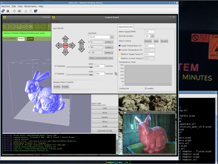
    I use the Ubuntu desktop-sharing program to view / control the downstairs programs in a window on my (larger) upstairs monitor, so I can fiddle with RepG from the Comfy Chair. There’s a moderate lag due to stuffing the GUI through the network, but it’s tolerable for small changes & tweaks. The webcam view occupies one corner of the screen.

    This is a staged reenactment showing the remote “downstairs” desktop in the left, with the “upstairs” desktop visible to the right:

    Remote Desktop Screenshot - lowres
    Remote Desktop Screenshot – lowres

    All the files live on our simpleminded server, which sits in the Basement Laboratory’s Computer Wing, and the PCs mount NFS shares from the server. I do all the bulk text editing & file fiddling from the Comfy Chair.

    So I save the STL file from the upstairs PC, flip to the window showing the downstairs machine’s desktop, copy the STL to a local drive to avoid lag during operation, run RepG to open the STL and slice it into G-Code, fire the Thing-O-Matic, and trot downstairs to watch the proceedings.

    As a rule, I don’t run the printer unattended, but now it looks like it’s a Bad Idea to run the heaters without being nearby. You knew that already, right?

  • NEMA 17 Shaft Adapter

    NEMA 17 5mm to 0.1875 inch shaft adapter
    NEMA 17 5mm to 0.1875 inch shaft adapter

    The NEMA standards for stepper motors don’t specify the shaft dimensions, alas. While most NEMA 17 steppers have 5 mm shafts, the X and Y axis motors in a Thing-O-Matic have 3/16 inch shafts: MBI belt pulleys with 4.76-ish mm ID won’t fit on 5 mm OD shafts.

    (Note: the “17” in NEMA 17 means the mounting holes are on a more-or-less 1.7 inch circle. The side of the motor frame will be close, but that’s not the controlled dimension. Some relevant diagrams live there.)

    I plan to replace the Y axis stepper with a better motor (I got a set of three, one of which is now driving the stepper extruder), which means either buying a new pulley or having some Quality Shop Time. Plus, a bit more length on the Y axis shaft than what comes standard would be a Good Thing, too.

    [Update: From the motor label, not that you’ll ever find one like it…

    • 38 mm case
    • Minebea-Matsushita 17PM-K150-P1V
    • No T6824-02

    ]

    So I built an adapter from 5/16 and 3/16 rod with a setscrew to grab a flat on the stepper shaft and a pin for the torque. The larger rod turned out to be La Salle Fatigue-Proof steel, not that it matters, and the smaller rod is plain old W-1 Water Hardening Drill Rod, both from Brownell’s, a long time ago in a universe far away. You could turn and drill the adapter from a single length of 5/16 rod if you prefer, but take some care to maintain the alignment.

    A bit of lathe & Sherline CNC work:

    • Face one end of the 5/16 rod
    • Drill half an inch with a #9 drill (0.196 + runout = 5 mm)
    • Drill another quarter inch with a #12 drill (0.189 = 4.8 mm)
    • Saw off 3/4 inch, face the raw end
    • Saw & face an inch of 3/16 rod
    • Epoxy little rod in big rod, set upright, wait overnight
    • Cross drill #43 and tap 4-40 near big end
    • Cross drill #56 for 0.045 music wire pin
    • Chamfer pin hole, clean, epoxy pin in place, wait overnight
    • File two flats on 3/16 shaft for MBI pulley setscrews
    Tapping shaft adapter
    Tapping shaft adapter

    I grabbed the small rod in the vise with the large rod resting on the top of the jaws while the epoxy cured, figuring that it’d be pretty much self-aligning. Not that a few mils one way or the other will matter, as it’s driving a timing belt in a flexy machine anyway.

    Cross-drilling the pin hole required eyeballing the center of the length of 3/16 rod within the 5/16 rod. It’s not critical, but avoid missing the poor thing entirely. You want to minimize the nested length, so as to keep the adapter as short as possible, but keep at least one diameter (3/16 inch) so as to maintain alignment.

    Tapping should involve a bottoming tap, but I used what I had and it worked out OK.

    Now, one reason I was willing to do this is that the stock Y axis motor shaft was already too short. As nearly as I can tell, the TOM dimensions were set before MBI started shipping those cork sound-deadening plates, because the shaft is recessed into the pulley by about the thickness of that plate.

    The MBI pulleys are an extremely tight fit on a 3/16 inch rod, so, rather than forcing the pulley, I enlarged the hub with a #12 drill (same as in the adapter) to get another 1.5 mil of clearance; it’s now an easy slip fit on the rod.

    Drilling MBI motor pulley
    Drilling MBI motor pulley

    Anyhow, the bottom flange of the pulley is 17 mm above the ridge on the motor and this one worked out to a bit over 20. No problem, I can just lower the motor a little bit, flip the pulley over to get the setscrew end of the hub on the top, and it’ll have plenty of room. A bit more shaft is much better than not enough, sez I.

    Y axis motor shaft extension
    Y axis motor shaft extension

    The motors came from the usual eBay seller complete with a squishy silicone sound deadening panel that turned out to be exactly the right thickness, when stacked atop a cork sheet, to put the pulley where it needed to be. I cut a second cork sheet, so as to isolate the bolt heads from that acrylic body panel, and it’s all good.

    Y axis motor with shaft adapter
    Y axis motor with shaft adapter

    Now, to print a suitable test object…

  • Un-milling Some Slots

    The first aluminum build plates had to fit around the gimcrackery atop my tweaked ABP: two solderless grounding lugs and a lump of Wire Glue. The new HBP setup put the grounding lug below the fixed plate and did away with the lump, so the removable plate could have five holes and a wiper cutout without any fancy trimming.

    I’d squared up three plates and machined only two for the ABP, so I had one plate that just needed drilling. Rather than machining two new plates, I filled the cutouts on the old plates with JB Industro Weld epoxy, flycut the excess, and drilled new holes.

    Flycut and drilled epoxy fill
    Flycut and drilled epoxy fill

    This was straightforward manual CNC: get the plate square on the table, touch off the plate edges, and then drill the holes in two steps.

    If those thin epoxy webs break off the outside of the holes, it’s not the end of the world: the plates won’t go anywhere because they’re indexed by the holes on the other side.

    Memo to Self: Next time, make a fixture to hold the plates relative to a starting hole and eliminate all the tedious alignment steps.

  • Thing-O-Matic / MK5 Extruder: Thermal Switch Block

    Thermal Switch Block on Thermal Riser
    Thermal Switch Block on Thermal Riser

    The best place to mount a thermal switch (or a thermal sensor, depending on how much you trust your circuitry) is on the MK5 Thermal Core, but that’s far too hot for the switches I have in hand. As a compromise, I decided to mount the switch on the Thermal Riser tube leading vertically upward to the Filament Drive gear: good thermal contact, a solid mount, and out of harm’s way.

    All the alternative locations seem worse. Tucking it inside the insulation wrap doesn’t provide a solid mechanical mount, so you don’t get a repeatable position and the leads get bent every time you move something. Bolting it to the plate over the Core looks solid, but that’s just a flat sheet of metal with four screws connecting it to the Core: no real thermal contact surrounded by lots of cooling air.

    One good omen: with an operating temperature well under 100 °C, JB Industro Weld epoxy will work fine and eliminate any need for fussy clamps and fittings.

    So I sawed off a random chunk of aluminum plate, squared it up in the Sherline mill, and poked a few holes in it. This doodle has dimensions roughly equivalent to the final object, but absolutely nothing is critical other than the 5/16 inch central hole:

    Switch block sketch
    Switch block sketch

    The 4-40 setscrew secures the block to the Thermal Riser. Aluminum expands considerably more than stainless steel, so I dropped a snippet of PTFE wire insulation into the hole as a rubberdraulic plunger.

    The lug on the top provides strain relief for the wires; it’s not an electrical connection. The modular phone cable trailing off to the Thermal Cutout box has wires insulated with low-temperature plastic, so a few inches of Teflon hookup wire keep them out of the Danger Zone.

    The small hole is just big enough for a thermocouple bead.

    This is what the thing eventually looked like, but I made some measurements before sticking that switch in place:

    Themal Switches - prepped and mounted
    Themal Switches – prepped and mounted

    Up next: measurements!