Ed Nisley's Blog: Shop notes, electronics, firmware, machinery, 3D printing, laser cuttery, and curiosities. Contents: 100% human thinking, 0% AI slop.
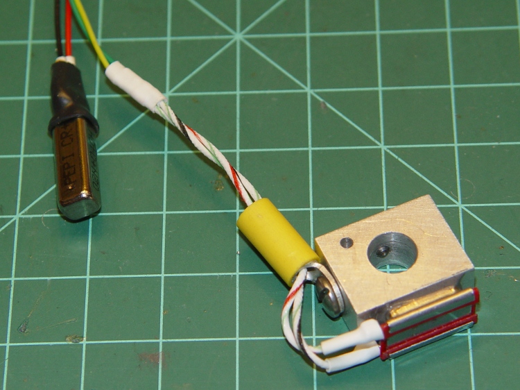
The best place to mount a thermal switch (or a thermal sensor, depending on how much you trust your circuitry) is on the MK5 Thermal Core, but that’s far too hot for the switches I have in hand. As a compromise, I decided to mount the switch on the Thermal Riser tube leading vertically upward to the Filament Drive gear: good thermal contact, a solid mount, and out of harm’s way.
All the alternative locations seem worse. Tucking it inside the insulation wrap doesn’t provide a solid mechanical mount, so you don’t get a repeatable position and the leads get bent every time you move something. Bolting it to the plate over the Core looks solid, but that’s just a flat sheet of metal with four screws connecting it to the Core: no real thermal contact surrounded by lots of cooling air.
One good omen: with an operating temperature well under 100 °C, JB Industro Weld epoxy will work fine and eliminate any need for fussy clamps and fittings.
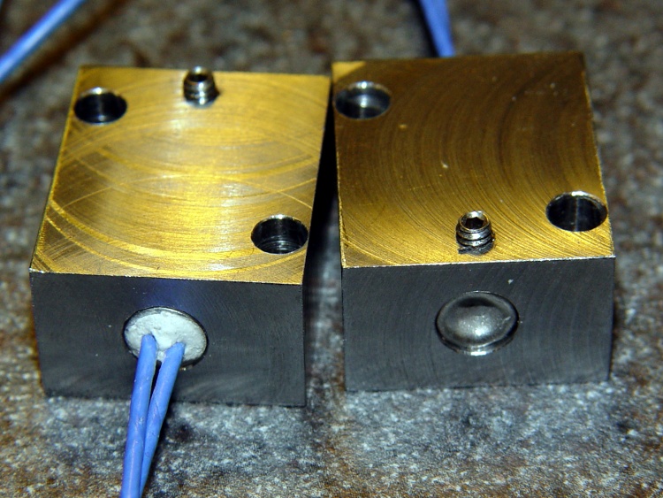
So I sawed off a random chunk of aluminum plate, squared it up in the Sherline mill, and poked a few holes in it. This doodle has dimensions roughly equivalent to the final object, but absolutely nothing is critical other than the 5/16 inch central hole:
Switch block sketch
The 4-40 setscrew secures the block to the Thermal Riser. Aluminum expands considerably more than stainless steel, so I dropped a snippet of PTFE wire insulation into the hole as a rubberdraulic plunger.
The lug on the top provides strain relief for the wires; it’s not an electrical connection. The modular phone cable trailing off to the Thermal Cutout box has wires insulated with low-temperature plastic, so a few inches of Teflon hookup wire keep them out of the Danger Zone.
The small hole is just big enough for a thermocouple bead.
This is what the thing eventually looked like, but I made some measurements before sticking that switch in place:
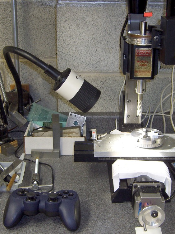
Eks forced me to take a pile of crap useful make-froms, including a gooseneck task lamp that was probably bolted onto a machine tool in its former life. It sported a 20 W halogen bulb, but looked to be just about exactly the right size for those LED floodlights, which is why I didn’t put up much of a fuss about taking it off his hands.
The LED lamps are much bigger than the halogen bulb, but they fit neatly into the housing diameter. All they needed was a bit more front-to-back room, which looked a lot like a chunk of PVC pipe. The housing screws together with a 1.5 mm thread that I can’t produce on my inch lathe; I’m still not set up for thread milling. This being a low-stress application with a lamp that ought to outlast me, I figured I’d just make the belly band slip-fit the two threads, glue it in place, and move on.
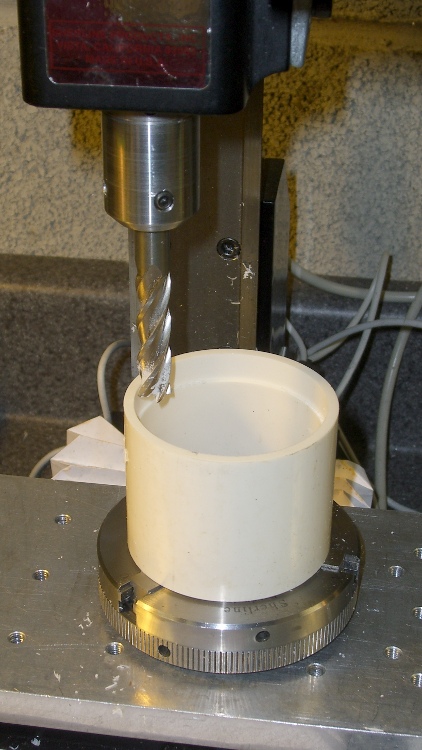
I sawed off a length of PVC pipe, faced off the ends in the lathe, then CNC milled a recess to clear the male threads on the gooseneck part (I hate precision boring in the lathe). Given the rather tenuous grasp of that 3-jaw chuck, I made two passes around the perimeter: pipe ID 52.1, thread OD 54.5, remove 1.2 mm all around, about 9 mm down.
Milling top recess
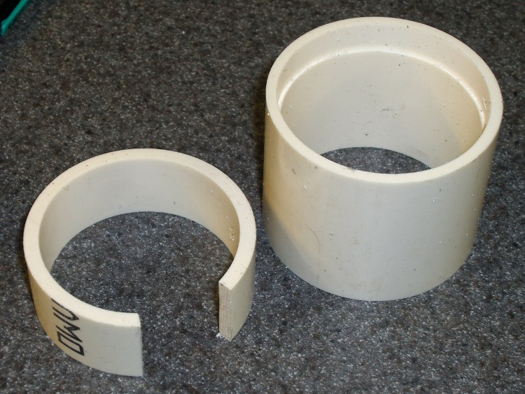
On the other end, the female thread ID = 52.2 and the pipe ID = 52.1, so I glued another ring of PVC pipe inside to provide enough meat to turn it down. Once again, saw off a ring, face the ends, then cut out a segment so that the OD circumference of the inner ring is just slightly smaller than the ID circumference of the outer pipe. The result looked like this:
PVC insert sizing
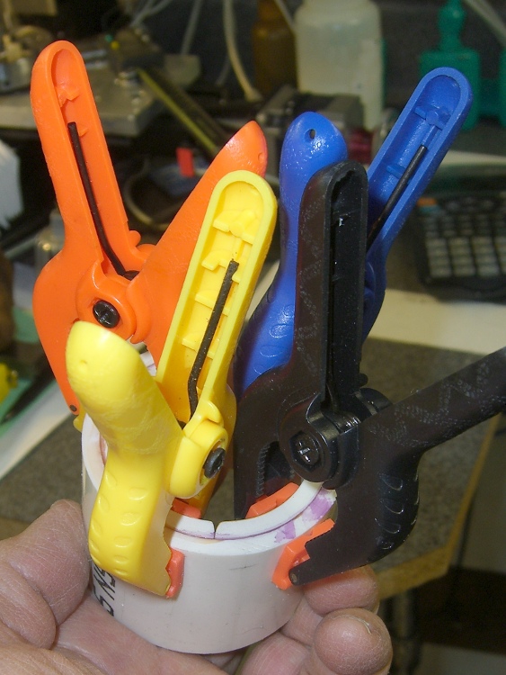
Apply a heat gun to the inner ring until it’s soft enough to stuff into the pipe, clamp it until it hardens, apply PVC cement, and clamp overnight. Contrary to appearances, the ends of the two pipes are flush at the surface. Once again, you cannot have too many clamps:
Clamped PVC insert
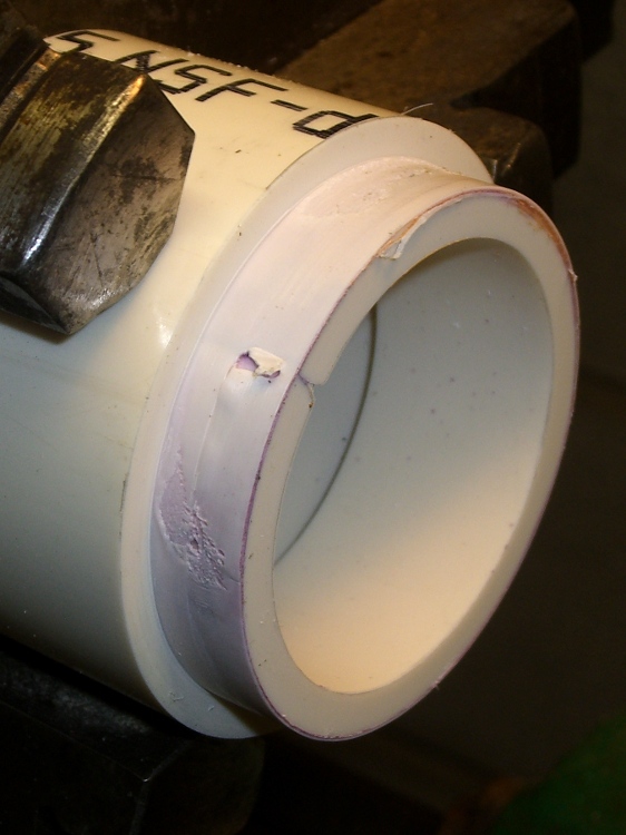
Turning down the outside to fit the threads shows just how little meat was left on that pipe:
Skinning down to the insert
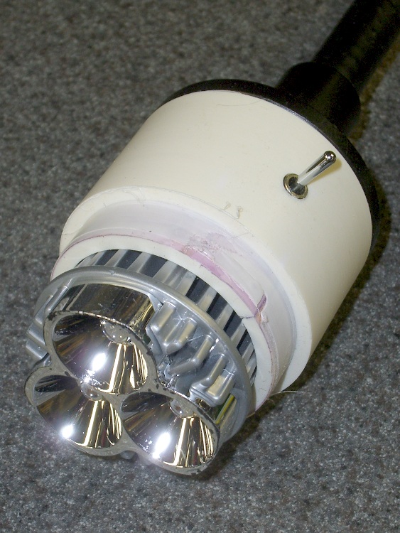
While it was chucked up (and despite my dislike of boring) I bored a bevel to accept the LED lamp and adjusted the OD so the lamp fit snugly between the end of the belly band and the lens holder on the front of the housing:
Floodlight in holder
The switch comes from the Parts Heap. A D drill puts a slightly undersized hole that’s just right for the threaded switch; I simply turned it in by hand. A length of zip cord carries the power up the gooseneck, where various ends get soldered to the switch and lamp.
I applied some hot-melt glue to the threads and pushed everything together:
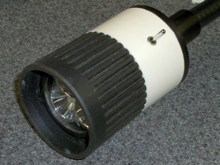
Finished LED Floodlight
The glass lens on the front fits in a molded holder with an annular air gap. The LED lamp housing has all those fancy cooling fins against the inner pipe, so there’s a bit of cooling air flow around the lamp and out through the rear black section. A thermocouple reports the lamp temperature gets up around 75 °C in a 14 °C shop; a 50 °C rise might be a tad warm in the summer, but we’ll see what happens.
The power supply came from the Parts Heap: a 12 V 1 A wall switching power supply in the shape of a wall wart. For now, the zip cord from the lamp terminates in a coaxial power jack that (amazingly enough) fits the wart’s connector, but I’ll eventually put a box in there somewhere.
Clamped the butt end of the gooseneck to the backsplash on the countertop under the mill and It Just Works!
This is a proof-of-concept lashup of a circuit to shut off the Thing-O-Matic’s power should the Thermal Core overheat. It vaguely resembles those doodles, but with the thermal switch cases grounded and an indicator for the main thermal switch.
[Update: You should read the rant at the bottom of that post to understand why this isn’t a firmware mod and doesn’t contain a microcontroller.]
Operation is straightforward:
The black NO (Normally Open) momentary switch energizes the DPDT relay, one NO pole of which then holds the relay power on.
The red NC (Normally Closed) momentary switch interrupts that circuit and releases the relay.
An NC thermal switch detects an overheated Thermal Core, opens that circuit, and releases the relay.
The other NO relay pole connects / disconnects the ATX power supply’s -Power On line from the Thing-O-Matic Motherboard. That connection requires a circuit-board cut to splice the relay into the Motherboard.
The LEDs:
Lower Green = ATX AC power on (from +5VSB power)
Upper Green = +Power On signal active
Red = Test / Fault (on = relay inactive)
Yellow = low over-temperature alarm
Orange atop box = high over-temp switch active
I included a second NO thermal switch that activates at a lower temperature, mostly because I had one, but that’s certainly not required. The multitude of LEDs makes for a happy-looking box; labels would be a nice touch, I agree.
When you turn on the ATX power supply, the Lower Green and Red LEDs turn on: the “Test” part of the “Test / Fault” indicator. Push the black button, the Red LED goes off, the Upper Green LED goes on, and the Thing-O-Matic is up & running. Push the red button, the TOM shuts down, and you’re back to the starting condition.
The Yellow LED goes on when the lower temperature switch goes on.
Shortly thereafter, presumably, the higher temperature switch opens, the Orange LED goes on, the TOM shuts down, and you’re left with the Lower Green, Yellow, and Orange LEDs: zowie! When the high temp switch cools off a bit, the Orange LED goes off and the Red LED goes on. After a while, the Yellow LED will go off, and you’re back to Square One again.
What’s not yet done: mounting the thermal switches to the Thermal Core in a way that’s mechanically solid, electrically isolated, and thermally dependable. I just got a bag of 100 °C NC switches, which make more sense than the 65 °C NC switches I’d been fooling with.
The wiring uses 4P4C and 6P6C modular phone connectors and cables, which are cheap & readily available, if not exactly proof against high temperatures. In normal use, failures tend to be open-circuit that will shut off the heater power. Take care not to position the cables so they melt first; they’re not intended as thermal switches.
Achtung: modular cable color codes are not standardized, particularly on the jack side, so pay more attention to the pin numbers than the colors. If I ever meet the guys who rearranged the jack colors, There. Will. Be. Gibbage.
A back view of the box shows a nice rectangular hole that’s obviously a manual CNC job on the Sherline, with no corner filing whatsoever. Hot melt glue holds the connectors in place, so I’m not showing off the inside:
Thermal lockout box – rear
The -Power On connection to the Motherboard requires the single cut shown in yellow:
Motherboard PCB Modification
It looks like this in real life, with the wire soldered to the Arduino header pin. Another dab of my Shop Assistant’s orange nail polish seals the PCB wound:
Motherboard -Power On modification
The remaining wires attach to the ATX power connector pins on the bottom of the board. The yellow wire passes through an unused mounting hole on its way to the top side, as above. Use a cable tie to tie the cable to the board, through a pair of otherwise unused RS-485 connector mounting holes.
Motherboard Connections – Bottom
While you’re chopping away at the Motherboard, add that isolating diode to keep +5 V USB power from turning the ATX fan with the power off.
The overall schematic (clicky for more dots):
Thermal Lockout Schematic
There is no corresponding PCB layout, because the circuitry forms a point-to-point hairball inside the box. If you were doing this for real, you’d want a PCB with a bazillion connections, but …
For example, here’s the FET driver for the Orange (it just looks Red) high temperature LED before a liberal application of heat stink shrink tubing:
Overtemperature LED driver hairball
You can test the thermal switches using a butane lighter.
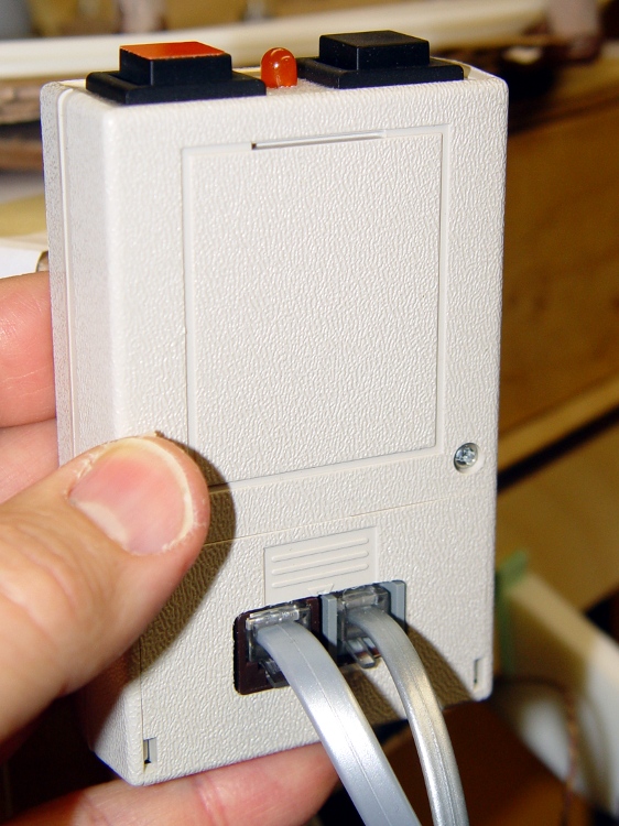
As part of the Thermal Lockout project, I planned to put a pair of big pushbutton switches on the end of a little Pactec box, thusly:
Pactec box – printed panel
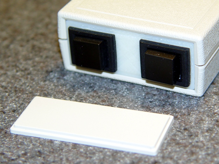
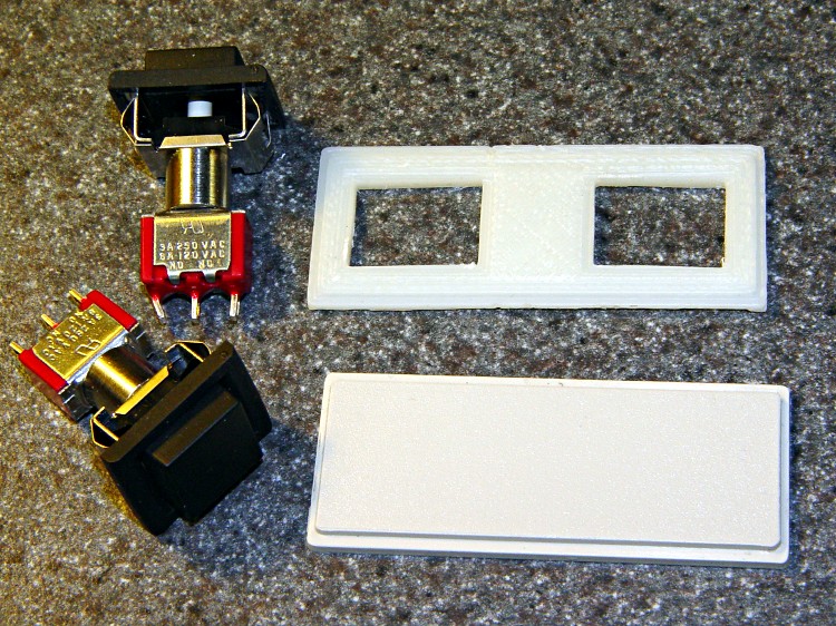
I was in the midst of figuring out how to clamp that tiny panel to the Sherline milling machine’s table and gnaw out those big holes, when I realized I could just print out a new panel with the holes already in place:
Pactec panels with switches
No muss, no fuss, no exciting chips… and no tedious corner filing, either.
The 3D model has the hole for an LED that I added later; the panel shown above acquired that hole during a brief conference with Mr Drill Press.
Thermal Cutout Box – switch plate model
In actual point of fact, I had to do a bit of edge filing for the switches, as the holes came out slightly undersized. The HoleWindage setting should take care of that for the next time around. The panel was a drop-in replacement for the original: all the outside dimensions & thicknesses were spot on.
The OpenSCAD source code:
// End panel for PacTec 61191-01 box
//    Panel 61580-01
// Ed Nisley - KE4ZNU - Feb 2011

Layer1Z = 1.50;
Layer2Z = 1.00;

HoleWindage = 0.55;                // approximately equal to extrusion width
Protrusion = 0.1;                // stick out over top and bottom

SwitchOffsetX = 15.0;

SwitchX = 16.0 + HoleWindage;
SwitchY = 12.0 + HoleWindage;
SwitchZ = Layer1Z + Layer2Z;

LedR = (5.0 + HoleWindage)/2;
LedZ = SwitchZ;

difference() {
 union() {
 translate([0,0,Layer1Z/2]) cube([55,22.5,Layer1Z],center=true);
 translate([0,0,(Layer1Z + Layer2Z)/2]) cube([52.6,19.5,Layer1Z + Layer2Z],center=true);
 }

 translate([SwitchOffsetX,0,SwitchZ/2])
 cube([SwitchX,SwitchY,SwitchZ + 2*Protrusion],center=true);

 translate([-SwitchOffsetX,0,SwitchZ/2])
 cube([SwitchX,SwitchY,SwitchZ + 2*Protrusion],center=true);

 translate([0,0,LedZ/2])
 cylinder(r=LedR,h=LedZ + 2*Protrusion,center=true,$fn=10);

}
Although that collet pusher works fine, the locking pin holder often teleported itself inside the vacuum cleaner. It recently reappeared on the far end of the main workbench, a good 15 feet away from the Sherline as the swarf flies. This, to misquote Churchill, is an impertinence up with which I shall not put.
Herewith, a replacement offering several advantages:
Won’t fit up the vacuum’s snout
Easy to grip
Perfect pin alignment
3D printing FTW!
It’s a flat block resting on the flat top of the pulley, with a nice arc matching the pusher’s OD. A small hole for the pin at exactly the right altitude makes the whole thing rock-solid stable: it slides firmly into position.
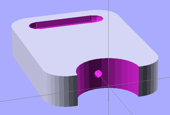
The 3D model looks like you’d expect:
Pin holder – OpenSCAD model
The finger grips were just for pretty, as you don’t need that much traction to extract the thing.
A similar view of the real object with the bottom surface up and some flash around the edges:
Locking pin holder – spindle end view
The as-printed block put the pin about 0.2 mm above the spindle hole, so I rubbed it on Mr Belt Sander (with the power off) until it fit. I printed the block on the aluminum plate platform; the Z height home setting evidently needs a tweak. However, the hole was exactly the correct distance from the top surface: flipping the block over fit perfectly.
This is a variation of Thing 6384: an aluminum plate sitting atop the Automated Build Platform’s bare heat spreader, minus the belt. HIs truly ingenious idea was to cover the plate with a thin layer of ABS to ensure adhesion: an ABS filament bonds very well to ABS!
Aluminum build plate in action
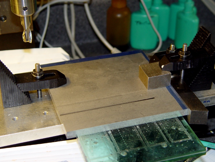
I started with a big sheet of 3/32 inch aluminum, a bit thinner than the 1/8 inch sheet he used, which is what I had in the Parts Heap. Bandsawed three chunks to rough shape, squared up the edges on the Sherline with manual CNC:
Squaring the sheets
That was complicated by the Sherline’s cramped work envelope. The 5/8 inch lathe bit on the right sits at exactly right angles to the X axis and serves as the reference plane. To make it happen:
Stack the three plates, clamp to table aligned against lathe bit
Whack off the far edge
Put clean edge against lathe bit
Whack off another edge
Measure / scribe 120 mm from each new edge (thus the blue stripes)
Align & cut
That actually worked quite well, although you’d think the angular error would build up as I rotated the plates. I checked and tweaked the angle after the first cut and it was all good.
Tight hole clearance
Then drill six clearance holes for the socket head cap screws holding the heater plate to the ABP; a #1 drill gave a few mils clearance, which is all it needs. The holes are 4 mm in from the edges of the 120 mm square, with the two middle ones at, yes, 60 mm.
However, there’s not much meat between the edge of the plate and the holes: call it 1.1 mm. If you do this, using 122 mm plates would produce less scary-close results. That’s why I like manual CNC for this stuff: no need to lay it out, tap in the numbers and it just Works.
My APB heater has a static drain connected to the heat spreader, so I milled a 2 mm recess around the right-hand screws to clear the lugs, wires, and Wire Glue blob. The silicone wiper gets its own cutout, which I made a snug fit so that the rubber would push the plate against the screw heads and hold it in place.
Milled recesses
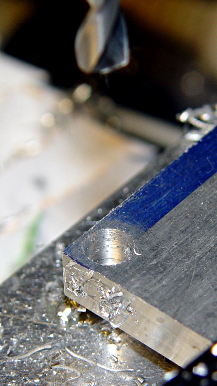
I machined recesses on only one plate, so I could incorporate any changes in the other two. The initial setup was atop a scrap plastic sheet which, as it turned out, wasn’t particularly flat. The edges of that not-quite-complete hole on the left were nasty-sharp.
Thin-shaved plate edge
Then clean off the ink with xylene, scrub the plate with a 220-grit sanding sponge, and it looks really nice. Impossible to photograph a uniform gray surface, though: the autofocus goes nuts.
While all that was going on, I’d dumped some MEK into a polyethylene jar along with a handful of calibration cubes and similar debris. I used MEK, rather than acetone, because it’s somewhat less aggressively flammable while still being a good solvent for ABS. Right now, the gunk has the consistency of thin honey, which may be too thick to spread easily; I’m still figuring this out. I apply the gunk with a folded coffee filter: scrape the puddle around to cover the whole plate, then let it dry. This is best done outdoors, except that right now it’s well below freezing out there.
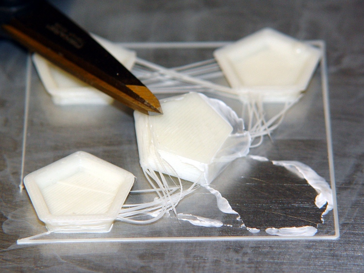
Here’s what the film looks like under the start of a quartet of dodecahedrons I ran off to see if they stuck properly:
ABS coating on aluminum build plate
The bottom surface looks like it was machined: dead flat,nice edges, good thread definition. The parts stick like they were glued to the surface, with no tendency to pull up at the corners.
The Outline thread shows some adhesion trouble for the first 10 mm or so. After that, it’s nailed right to the ABS film. That’s why I use Outline, at least until I figure out a better way to start the thread.
After I finish the next two plates, I’ll have a somewhat quick-change build platform: pull the hot plate off (holding it with pliers!) and slap a new one on. Not as convenient as the ABP, but much better for building precision parts like gears and extruder motor mounts.
MBI sent me a selection of 1/4-inch cartridge heaters to evaluate, seeing as how I’ve been such a pest on the subject of those poor aluminum-case power resistor heaters. Thanks, Zach!
I initially thought I could punch the cores out of the resistors and slip the cartridge heaters into the holes, but it turns out the resistor bodies aren’t quite the right size: slightly too short with slightly too large holes. So it goes. Some earlier thoughts live there.
This is a first pass at building mounting blocks to attach cartridge heaters to a stock MK5 Thermal Core. Ideally, you want a solid Thermal Core with a hole or two for the heaters next to the filament extrusion nozzle, but that requires fancier machining that I’m ready for right now. The fabled nophead shows how that looks for a ceramic power resistor.
The obvious question is whether you want a single high-wattage cartridge heater or a pair of low(er)-wattage units. I think a core-with-hole can get away with a single heater, which is also the lower-cost option. My thermal measurements suggest the Core is pretty much isothermal, so there’s no problem with distributing the heat evenly from one side to the other.
However, adding two lower-wattage heaters to a stock MK5 Thermal Core makes more sense, because the interface between the blocks and the Core seems to run a bit under 1 °C/W. A single 40 W heater would thus run 30-40 °C higher than the Core: call it 260 °C. IMO, that’s much too high for something an inch away from a plywood frame and an acrylic support structure.
A pair of 25 W heaters would run at 245 °C-ish. That’s still pretty hot, but every little bit helps. I’ll start with that arrangement and see how it works.
Block top and bottom
The blocks are ordinary steel from the Scrap Box: a convenient length of 1×1-inch bar stock that somebody else had made into something else a long time ago. I bandsawed off four 1×1-inch slabs, each about 5/8″ thick. A second bandsaw cut turned the square slabs into rectangles. I finished two blocks; the other two slabs await more experience with how these work.
I squared up the blocks with a flycutter in the Sherline, then sanded down the bottom surface a bit. The thermal tests suggest the contact is Good Enough with a reasonably flat surface, so I settled for a used-car finish: high shine and deep scratches. They’re actually smoother than the pictures would have you believe.
The Thermal Core has hard inch dimensions (minus cleanup cuts): 1 inch front-to-back and 13/16 inch tall. I generally work in metric, so the sketch at the bottom has everything in millimeters.
The mounting blocks have holes matching the resistor footprint. I drilled clearance holes for the heads of the original M2 socket head cap screws, ran an end mill down the hole to flatten the bottom, then drilled clearance holes for the threads. Those holes are perilously close to the edge, but the blocks really don’t want to be any taller. Perhaps use a less-generous clearance?
The alternative would be to mill a flange along the edge to match the resistor mounts and put the SHCS heads in free air, but that seemed like more work and it would cramp the thermal path from cartridge to block.
I also thought about chamfering the edges to make the blocks look less, well, blocky, but that’s in the nature of fine tuning.
The cartridge heaters slip-fit into a nominal 0.250 hole; the samples are 0.247 to 0.248 and (from what I read) the diameter tolerance stays on the minus side of 0.250. I don’t have a 0.250 reamer, which is how you get a precise hole ID, so I’ll go with drilled holes. Fortunately, I have a set of letter-size drills in nearly new condition:
A drill = 0.234 to poke a hole in the block
E drill = 0.250 to get the final diameter
The final holes worked out to be exactly 0.250 inch, to the limits of my measurement ability, which I will declare to be Good Enough. The cartridges have a loose slip fit with no side-to-side play.
The cartridges expand when heated and squeeze against the hole to make good thermal contact. While cool, however, they can slide out without much urging, so I added a 4-40 setscrew. It’s on the butt end of the cartridge heater shell, away from the leads, so if a cartridge becomes one with the block I can drive it out with a pin punch. Putting the setscrew at the end with the wire leads makes more sense (it’s cooler there), but then you’d be beating the entire length of the cartridge out past the setscrew hole.
The setscrew and the M2 SHCSs get a liberal dose of anti-seize grease before assembly.
Here’s what the holders looked like, just before bolting them in place:
Cartridge heaters in blocks
Doodles with the more-or-less as-built dimensions: