Ed Nisley's Blog: Shop notes, electronics, firmware, machinery, 3D printing, laser cuttery, and curiosities. Contents: 100% human thinking, 0% AI slop.
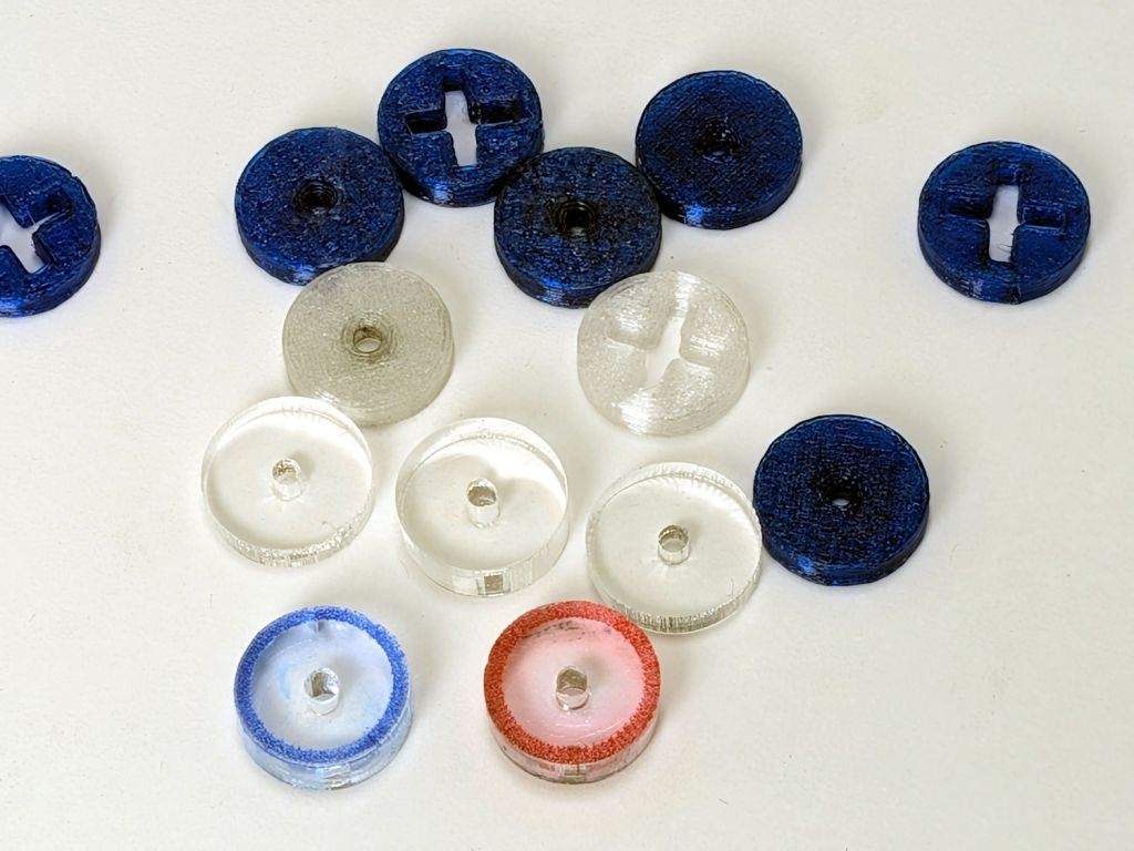
So the engraved ring on the two in the front row carries a cheerful Sharpie color to make them stand out. I wanted to use fluorescent acrylic, but I don’t have any 4 mm sheets and stacking a pair of 3 mm sheets → 6 mm will be too thick for the pencil tip.
What looks like dirt on the red guide comes from internal reflections or the lack thereof: it’s perfectly transparent in person, honest.
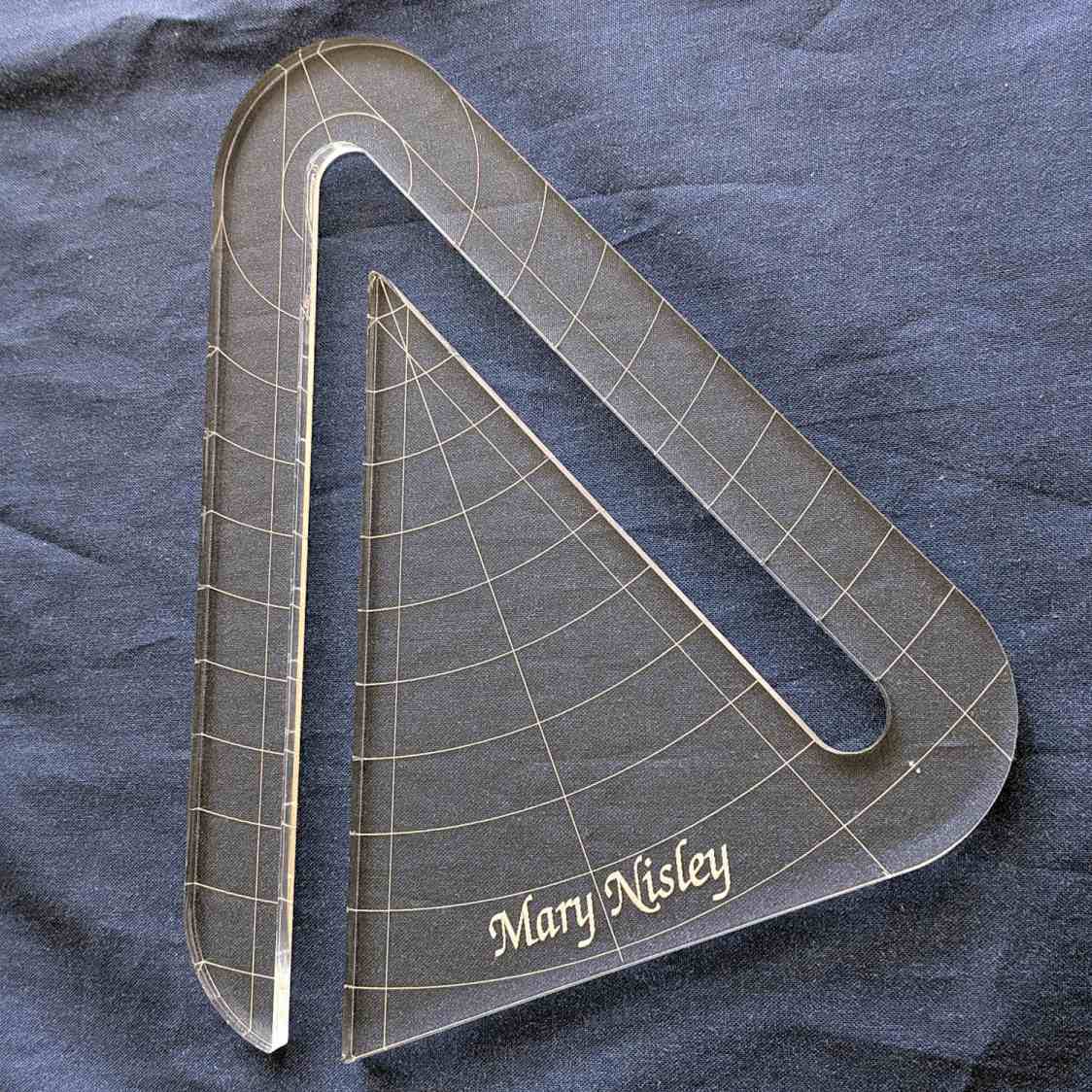
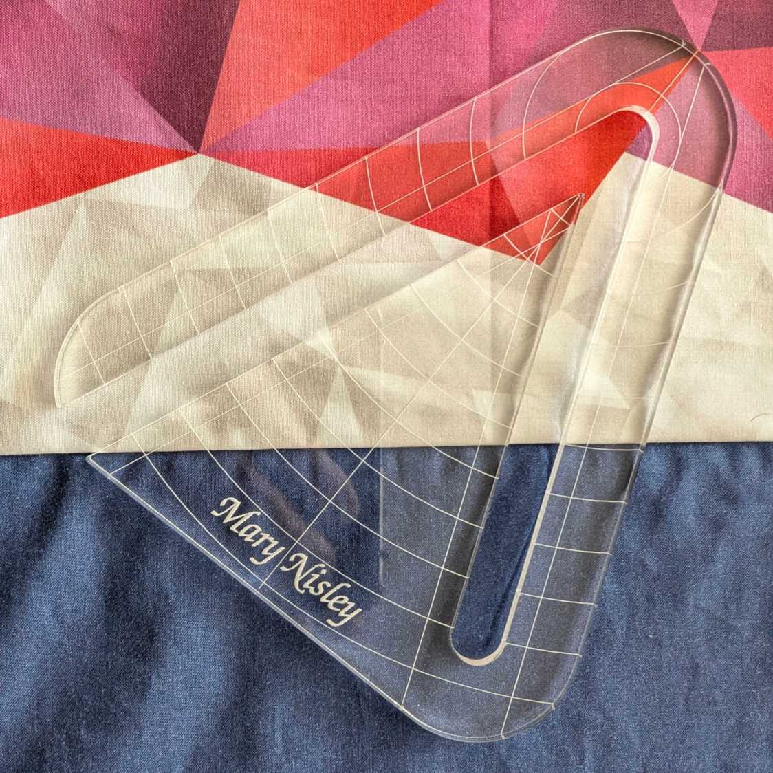
Mary’s current quilt project has a corner design with an essentially infinite number of 45° triangles, which another custom ruler will simplify:
45° Quilting Ruler – finished
That’s the end result of several iterations, proceeding from doodles to sketches to increasingly accurate laser-cut prototypes:
45° Quilting Ruler – prototypes
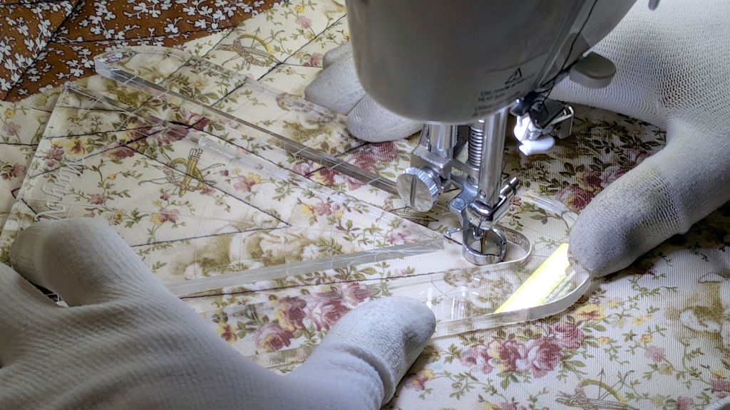
A “ruler” in quilting parlance is a thing guiding the sewing machine’s “ruler foot” across the fabric (or, for sit-down machines, the fabric under the foot) in specific directions:
45° Quilting Ruler – in use
That’s a practice quilt on scrap fabric: quilters need prototypes, too!
The foot is 0.5 inch OD, within a reasonable tolerance, which accounts for the slot width in the ruler. It’s also intended to run against 1/4 inch thick rulers, which accounts for the thickness of that slab of acrylic.
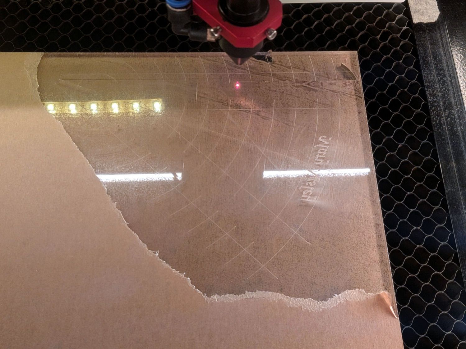
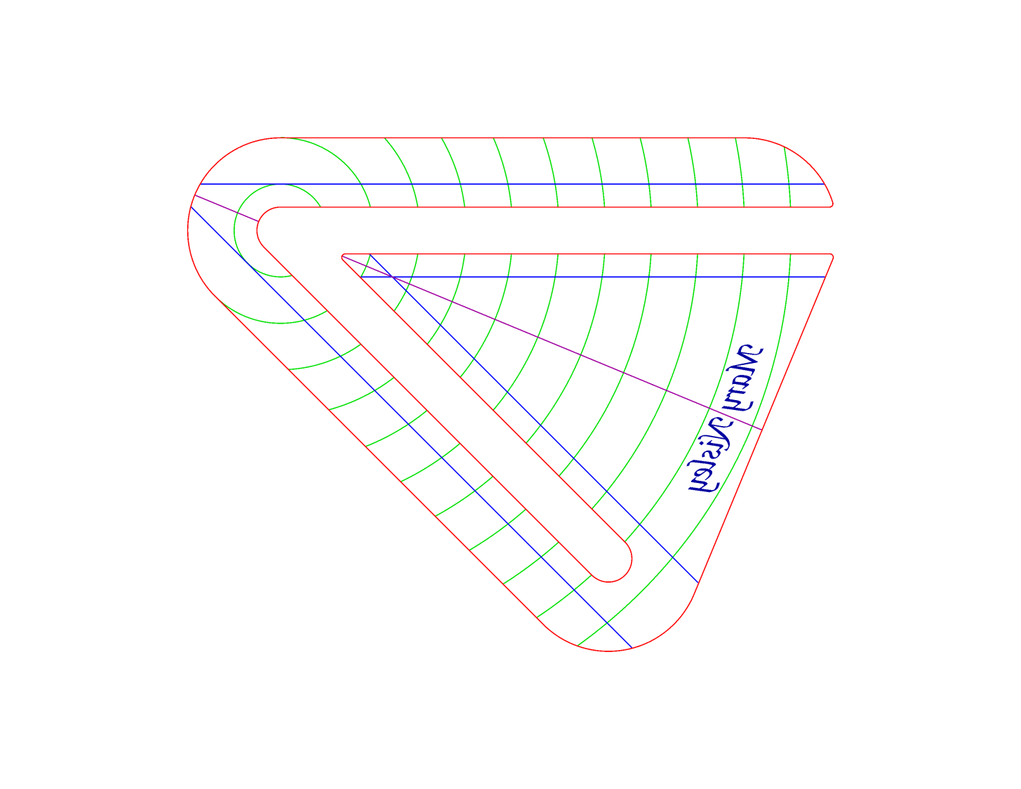
The engraved lines & arcs are on the bottom of the ruler to eliminate parallax errors against the fabric, so the bottom is upward and the text is mirrored for the laser:
45° Quilting Ruler – cutting
Although fluorescent green acrylic may have higher visibility, clear seems adequate for the fabric in question:
45° Quilting Ruler – colored fabric
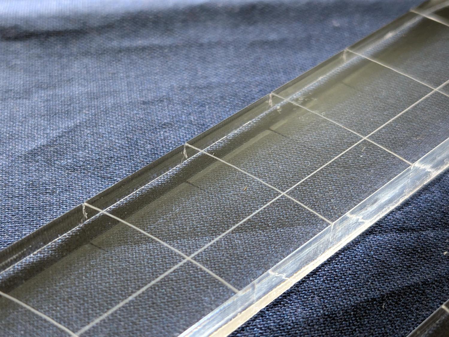
I very carefully trimmed the arcs against the ruler outline using LightBurn’s Cut Shapes, which turned out to be a Bad Idea™, because the high-current pulse as the laser fires causes a visible puncture wound at the still-to-be-cut edge:
45° Quilting Ruler – edge damage
Those are not straight lines and the plastic isn’t bent!
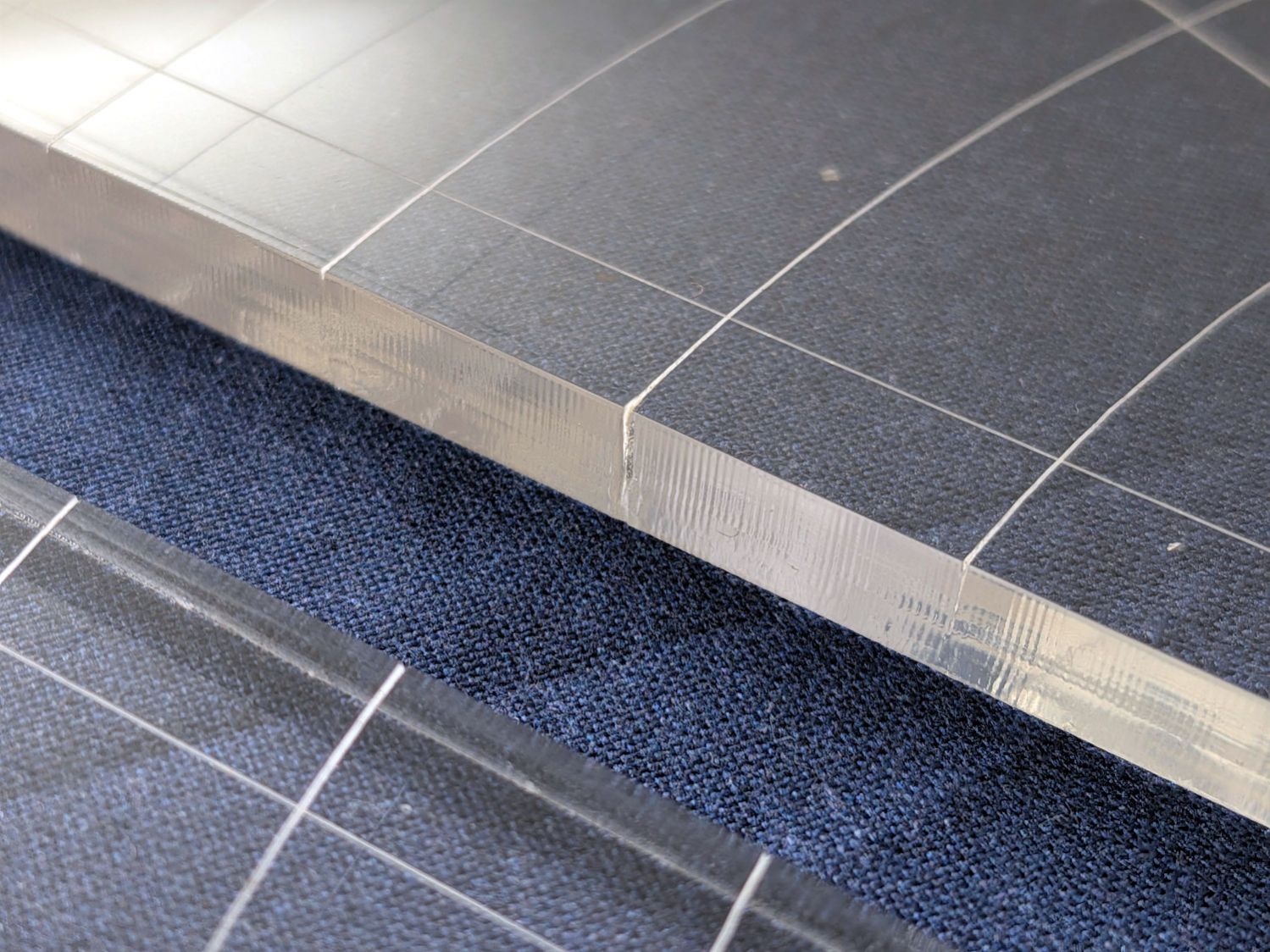
A closer look:
45° Quilting Ruler – edge damage – detail
The arcs without wounds started from their other end and stopped at the edge, which is perfectly fine.
The wounds are unsightly, not structural, but the next time around I’ll extend the markings a millimeter beyond the edges into the scrap material.
The overall design looks busier than it is, because I put different features on different layers in case they needed different settings:
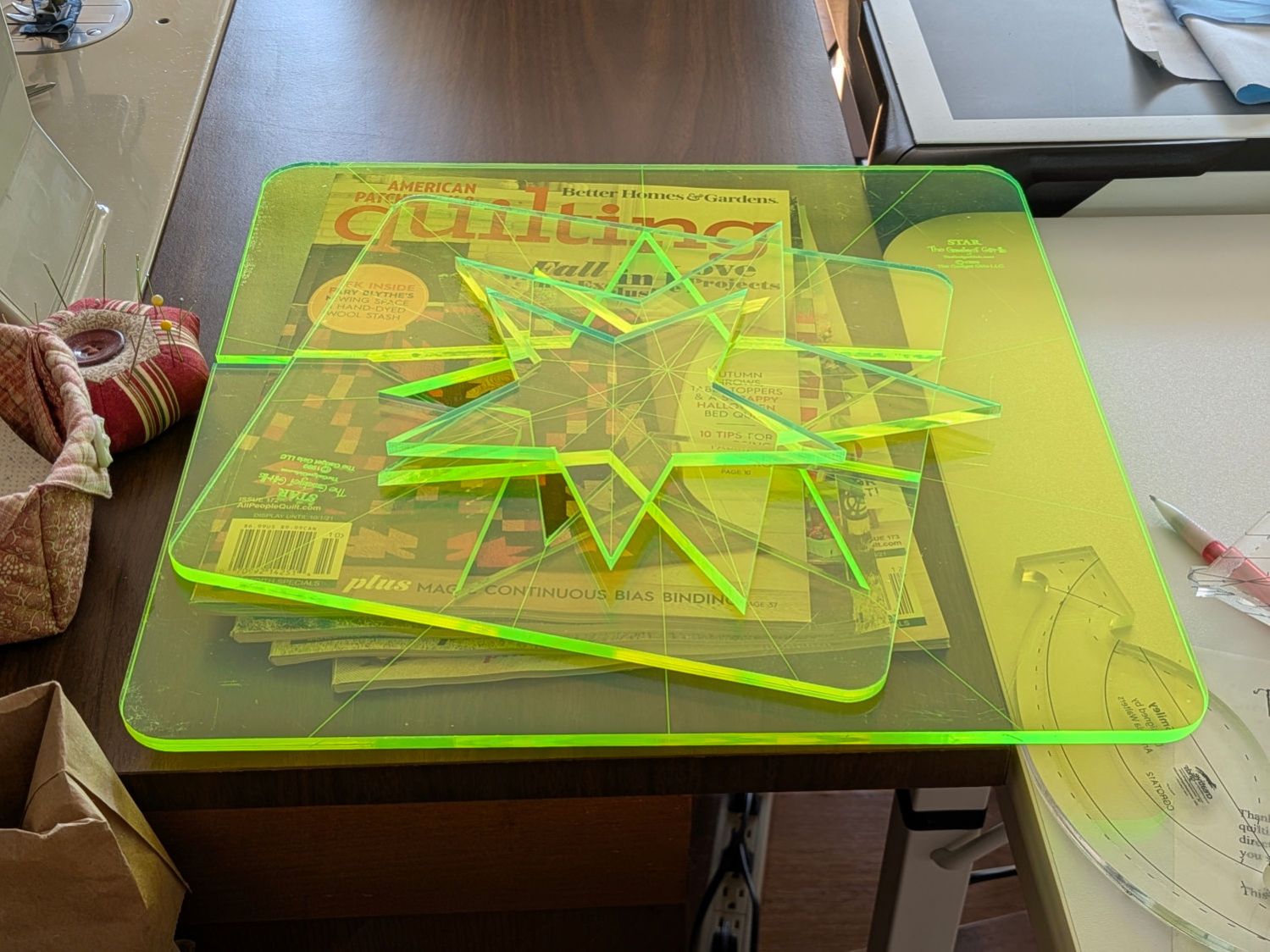
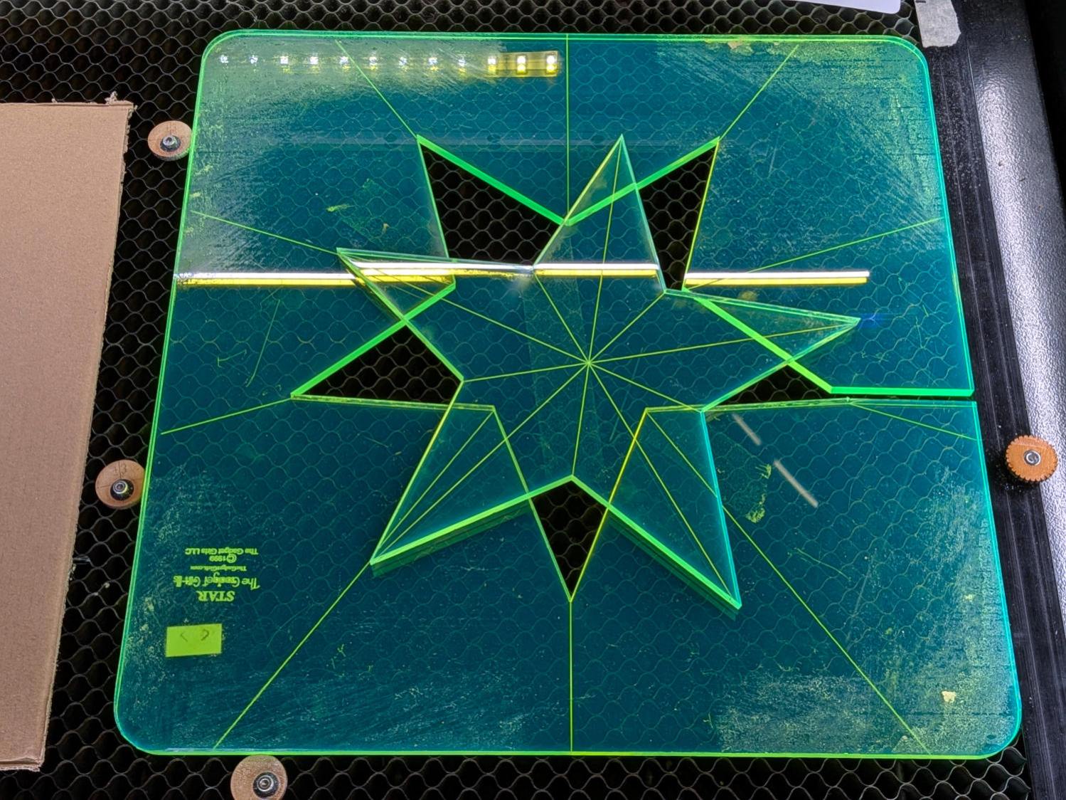
Mary picked up a pair of Star quilting rulers from the Quilting Guild’s “exchange” table:
Star quilting ruler – finished
They’re 1/4 inch laser-cut acrylic slabs dating back to the turn of the millennium, when laser cuttery wasn’t nearly as common as today. Apparently, the (now long gone) Gadget Girls had a problem with their laser: the larger star had eight of its ten lines not cut completely through the acrylic. The protective paper on the back had small perforations along a few of the lines, but nothing for most of them.
Well, I can fix that.
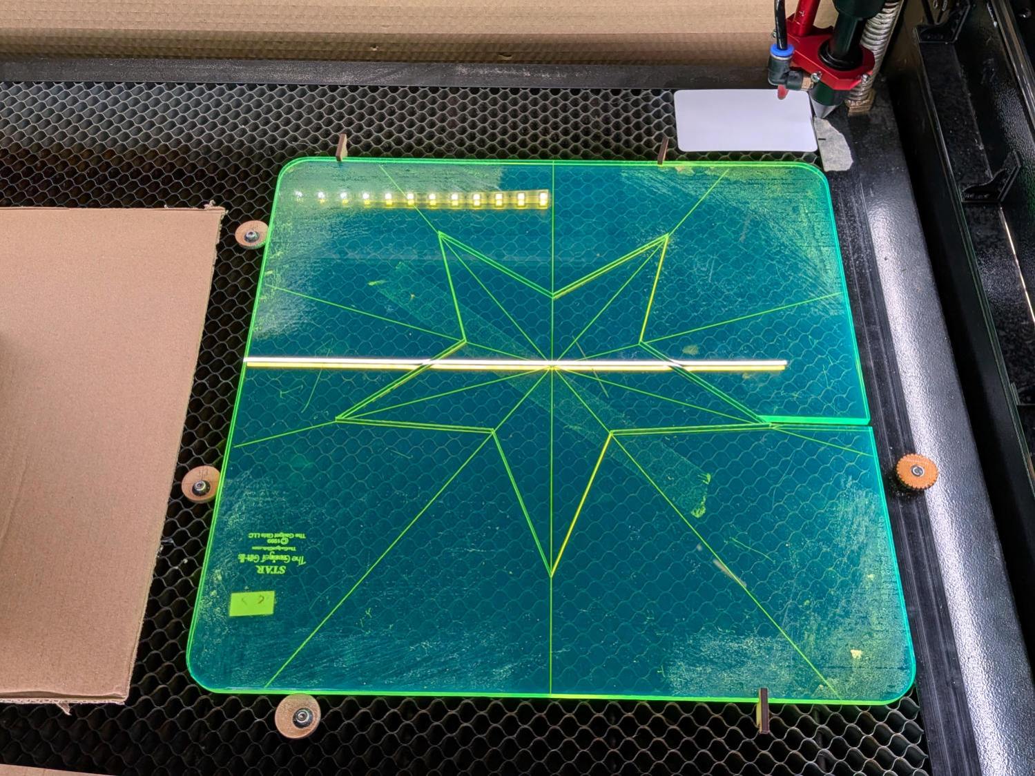
Lay the slab on the platform and lock it in place so it cannot move:
Star quilting ruler – laser setup
That’s with the original bottom side facing upward, so the laser beam will hit the uncut part of the lines.
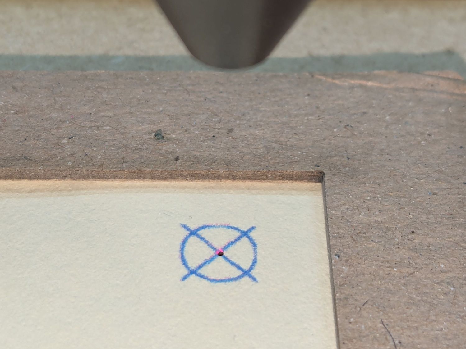
Focus the laser atop some scrap 1/4 inch acrylic, then verify the red dot pointer is exactly concentric with the CO₂ beam by firing a test pulse, as in this punched card:
Red dot vs printed target vs laser spot alignment
Adjust as needed.
Jog the laser to put the red dot pointer exactly at a star point:
Star quilting ruler – laser point alignment
Hit Get Position in the Laser window so LightBurn knows where the laser head is located.
I’ve added the targets I normally use for LightBurn’s Print and Cut alignment to its Art Library, so I dragged one to the workspace, then hit Move to Laser Position to snap the target directly onto that point of the star.
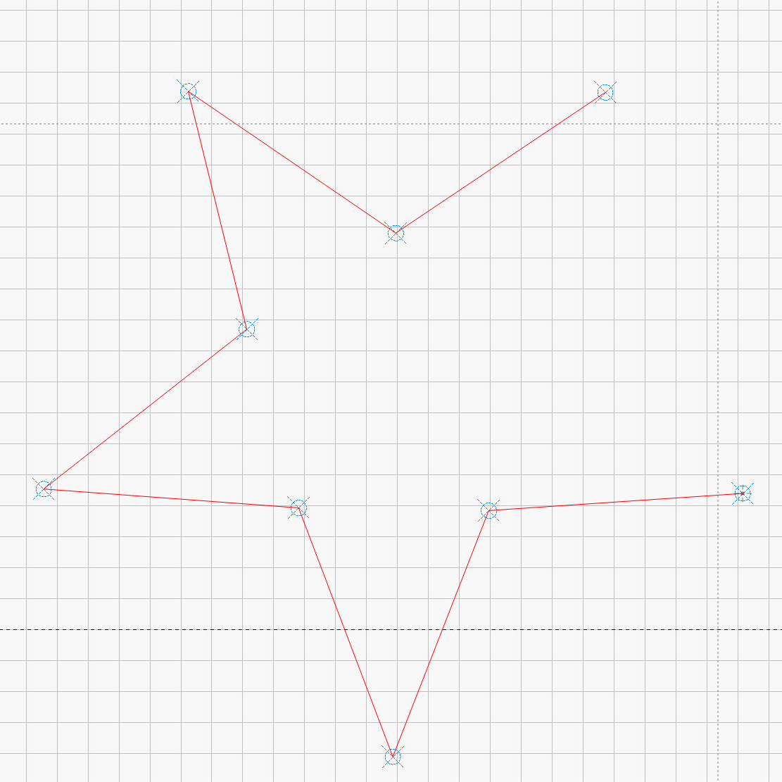
Repeat for vertices along the star, then draw a multi-segment line = path between the target centers:
Star Ruler Re-cutting – LightBurn layout
That’s one continuous path from the upper right, counterclockwise around the star, ending in the center right. The missing pair of lines (and the vertex between them) were already cut, so I didn’t need to locate them.
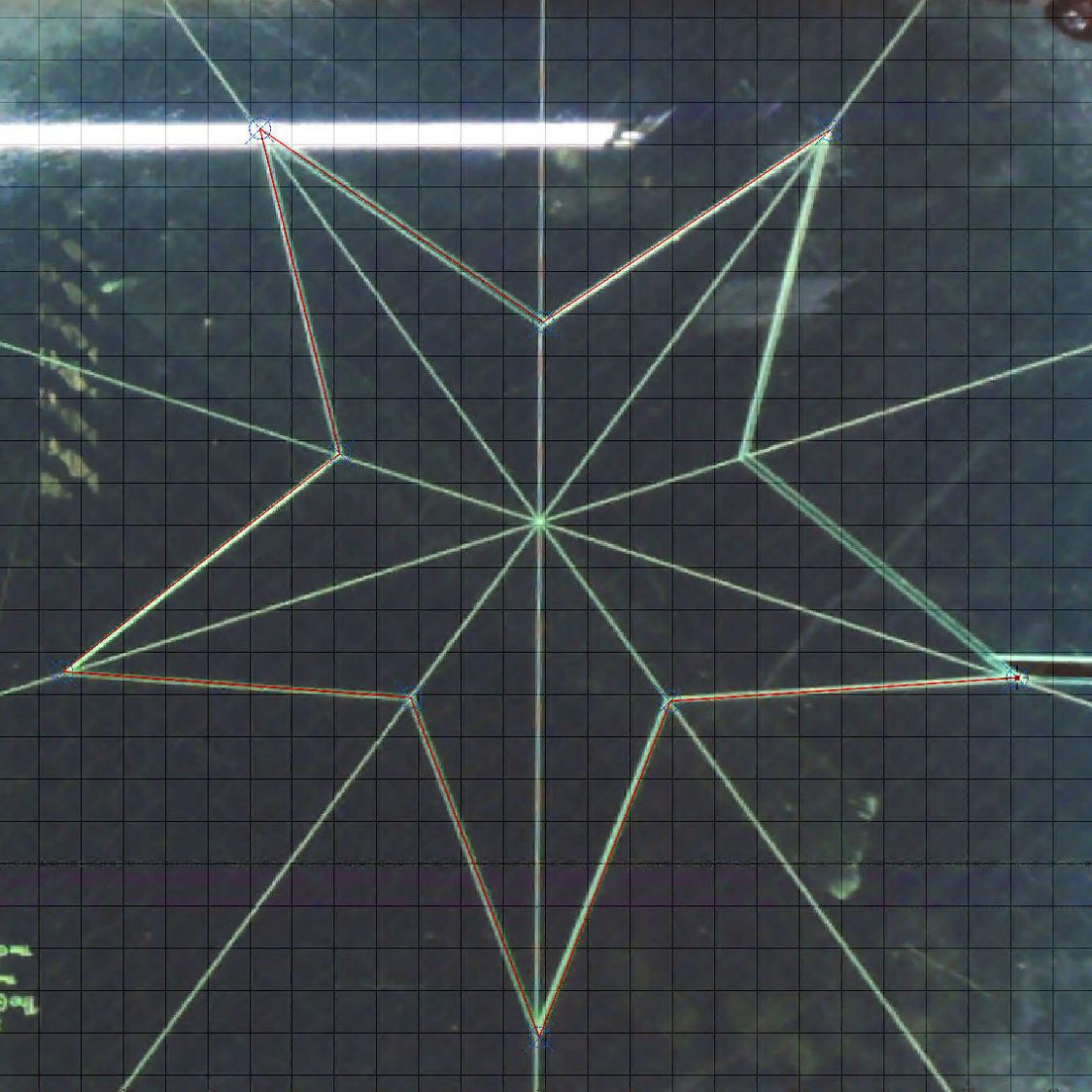
The camera view shows the alignment, although IMO the camera simply isn’t capable of such finicky alignment:
Star Ruler Re-cutting – LightBurn layout overlay
As a confidence builder, I selected each target, moved the laser to that point, then fired a test pulse to verify the hole hit the vertex. In most cases, I couldn’t see the hole because it was within the original cut.
My 60 W laser can’t cut through 1/4 inch = 6 mm acrylic in a single pass, so I use a 10 mm/s @ 60% pass to get most of the way through and a 20 mm/s @ 60% pass to complete the cut. That seemed excessive for a mostly cut path, but a single 20 mm/s @ 60% pass didn’t completely clear the uncut sections.
So I used the normal two-pass cut and the star lifted right out:
Star quilting ruler – victory
Happy dance!
Although it is not obvious from the pictures, the star is not symmetric: it fits into the sheet in only one of its ten possible orientations. I will never know if that was a deliberate stylin’ decision or the result of hand layout before CAD spread throughout the land.
I managed to locate the vertices so accurately that the repeated cuts left edges indistinguishable from the original cuts on the two free sides, which was a pleasant surprise.
Mary promises to do something with those stars when she’s done with her current project(s). She may want the slab of acrylic around the large star trimmed into a smaller and more manageable decagon, in which case I will suddenly have a bounty of thick fluorescent green acrylic.
The corners of Mary’s current quilt project need a 16 inch diameter circle, but my Drawer o’ Drawing Tools that should hold the trammel (distinct from trommel) point & pencil for a steel rule came up empty. While the TEC drawing kit has an extension leg for its compass, IMO it’s entirely too flexy for general use.
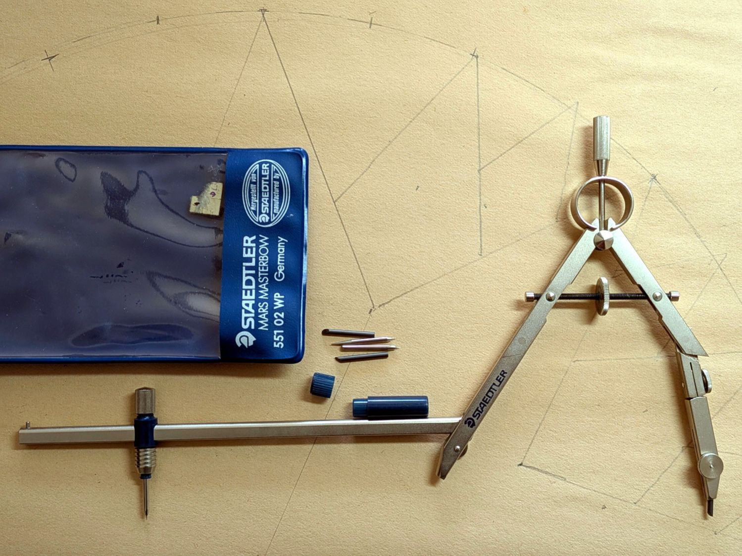
Further heap probes produced a Staedtler Mars Masterbow 551 02 WP compass with a robust extension leg:
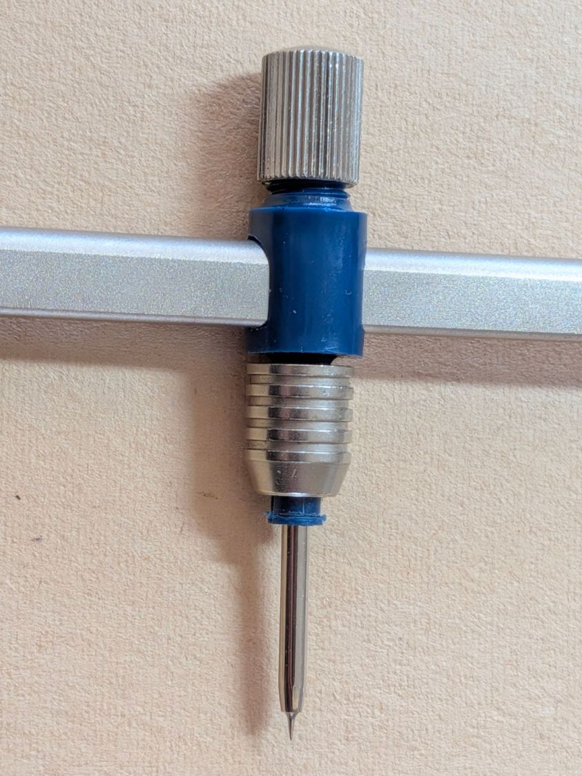
Staedtler Masterbow – 551 02 WP assembled
It was likely a surplus deal and, to the best of my knowledge, has never been used, so that picture documents how the extension leg fits into the compass. It arrived with the lead in that compass leg, causing some confusion.
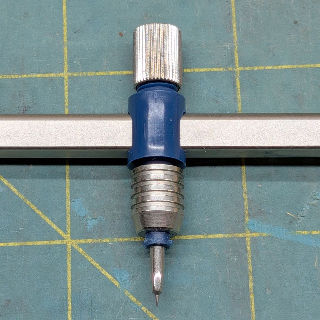
The key is to remove the point from that leg, insert the extension leg into the hole, then tighten the screw to clamp the leg in place:
Staedtler Masterbow – leg socket
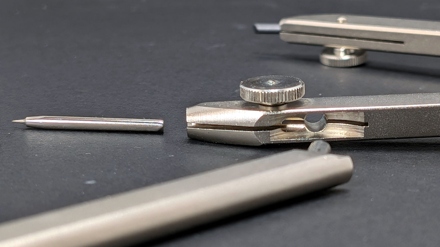
The collet holding the point was either manufactured incorrectly (which I find hard to believe, because Staedtler in a package embossed “Western Germany”) or suffered damage along the way, as the only point fitting into it stuck out much too far:
Staedtler Masterbow – bow collet wrong point
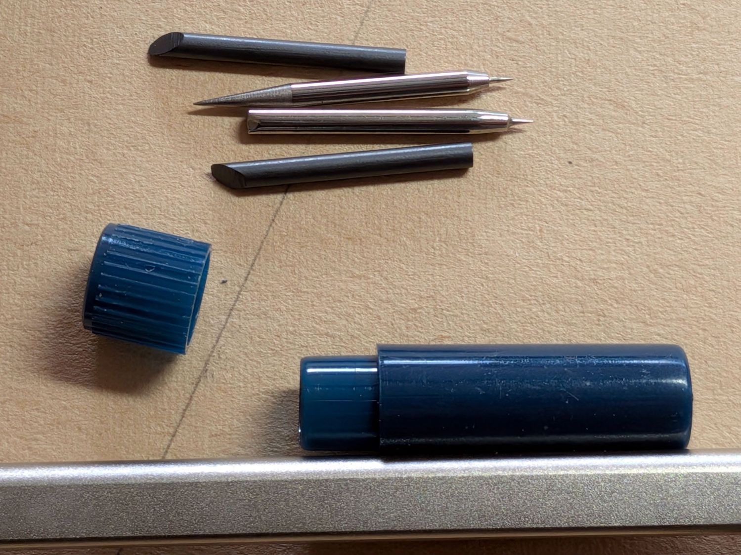
The small container in the top picture held two spare leads and two other points:
Staedtler Masterbow – point assortment
It turns out the blunt end of the bottom point should fit into the collet, but I had to ream the collet jaws with a (hand-turned in a pin vise) 2.1 mm drill to let that happen:
Staedtler Masterbow – bow collet resized
Then everything lined up correctly and drawing could proceed, although the collet closer doesn’t (seem to) contribute anything to the proceedings.
The thumbscrew adjustment on the compass makes it much more rigid, even with the extension leg sticking out there for an 8 inch span.
I can (now) put the lead in the bow collet and the point in the compass, but IMO it’s easier to hold the compass while drawing around the circle. Your mileage, in the unlikely event you have one of these, may vary.
They definitely don’t make them like that any more …
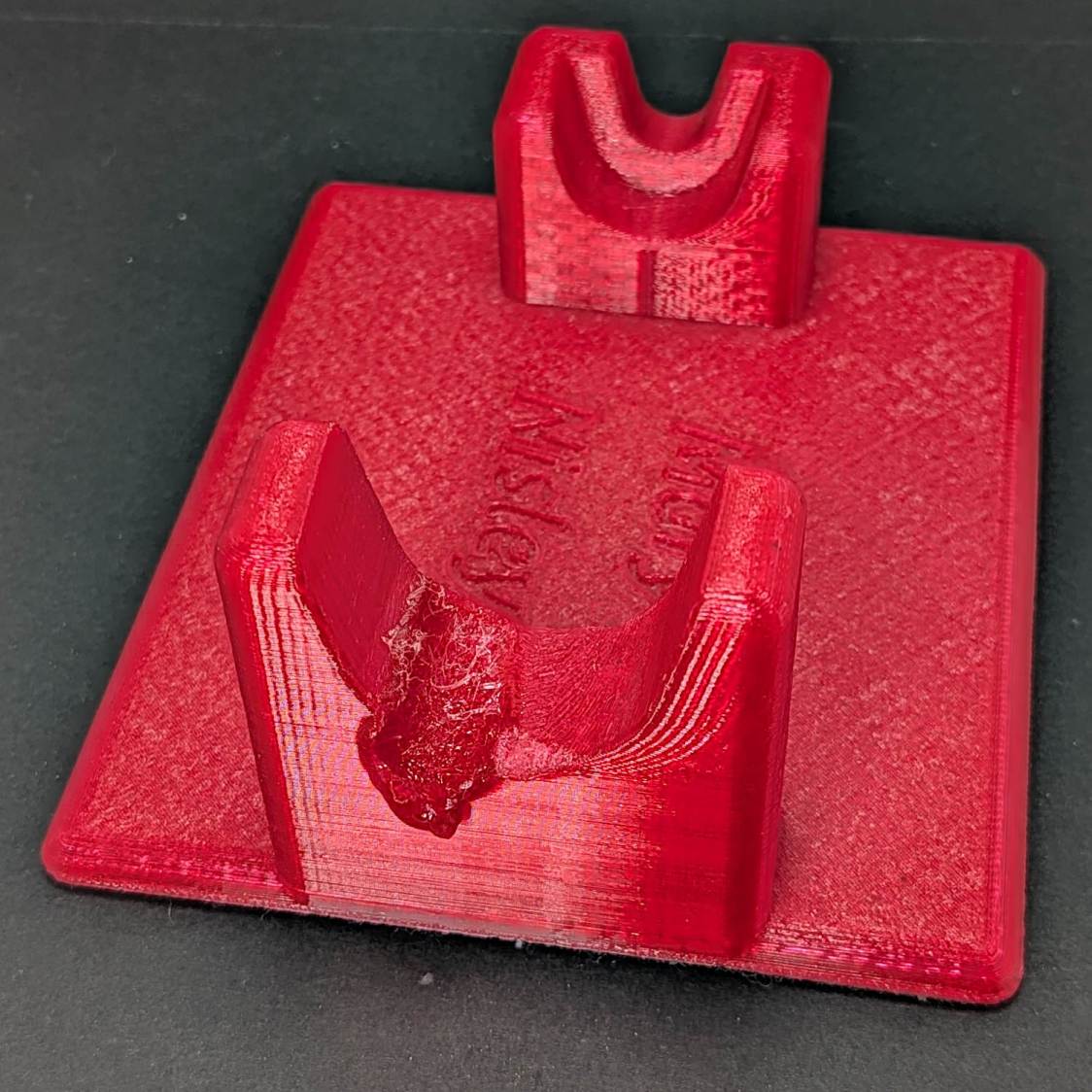
The 3D printed Clover Mini-Iron holder served well over the last decade (!), even after one of Mary’s buddies misplaced the iron during a quilting bee:
Clover MCI-900 Mini Iron holder – melted
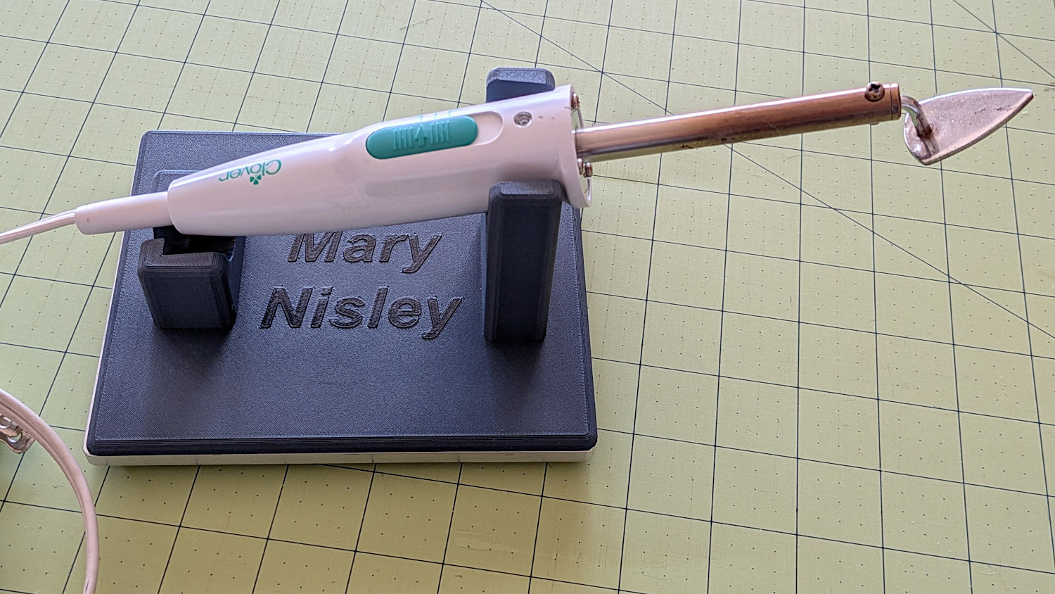
She asked for a new holder that put the iron at a higher angle for easier gripping, which required only slight tinkering to boot the OpenSCAD code into the current decade:
Clover MCI-900 Mini Iron holder – higher angle
The letters stand one layer proud of the surface just to see what that looked like. I think it’s a nice touch.
The alert reader will note the cord end isn’t quite snugged into its recess. In normal use, the cord hangs over the edge of the sewing table and pulls the iron into place.
I embiggened the base to fit an aluminum plate from the stockpile, because that same cord tends to pull the holder around on the table. The plate puts enough weight on the silicone rubber feet to hold it firmly in place.
A layer of good double-stick tape strips bonds the aluminum plate to the PETG iron holder, after I once again discovered that craft adhesive sheets do not bond to PETG.
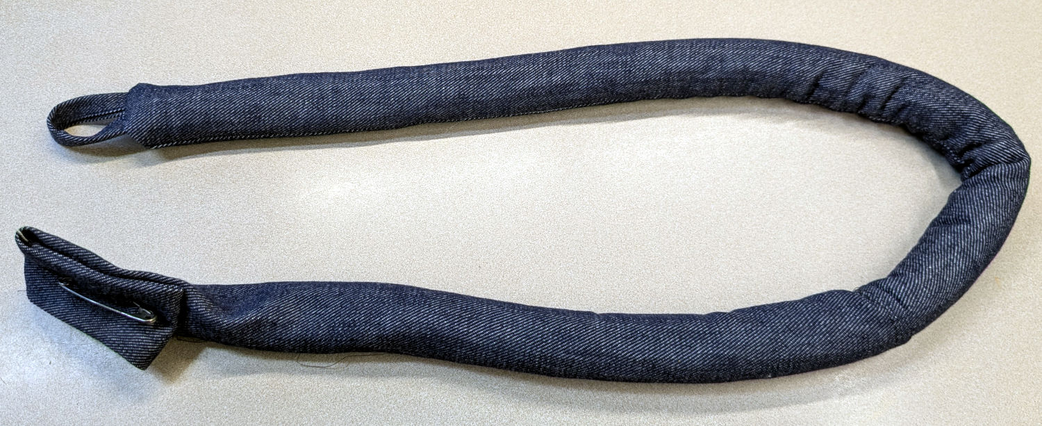
Mary made a frame weight to maintain tension on the fabric in the HQ Sixteen longarm:
Longarm fabric frame weight
It’s a sturdy cloth tube filled with BBs, somewhat like a grossly overweight door snake (a.k.a. draft stopper).
The bottle of 6000 copper-plated steel BBs arrived in an overwrap bag of the sort Amazon applies to all bottled products. This was a Good Thing, because the scrap of packing paper did nothing to cushion the bottle in an otherwise empty box. The bag contained most of the shattered cap and a few BBs, with escapees rattling around inside the box and surely a few left along the way.
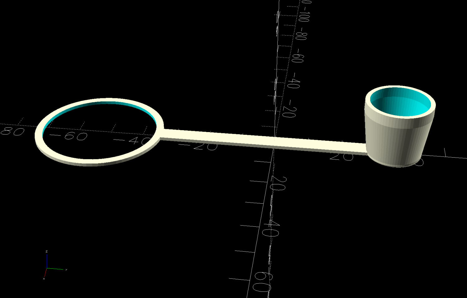
So I conjured a replacement cap from TPU:
Crosman BB bottle cap – solid model – build view
It fits around the bottle neck and snaps onto the spout just like the original:
Crosman BB bottle cap
Except this one is unbreakable.
The strapless TPU cap was a quick test to verify the fiddly shoulder snapping onto the bottle snout:
Crosman BB bottle cap – solid model – section view
As it turned out, we poured all 6000 BBs (minus those few lost-in-transit strays) into the cloth tube, but the bottle will come in handy for something someday.
This file contains hidden or bidirectional Unicode text that may be interpreted or compiled differently than what appears below. To review, open the file in an editor that reveals hidden Unicode characters.
Learn more about bidirectional Unicode characters
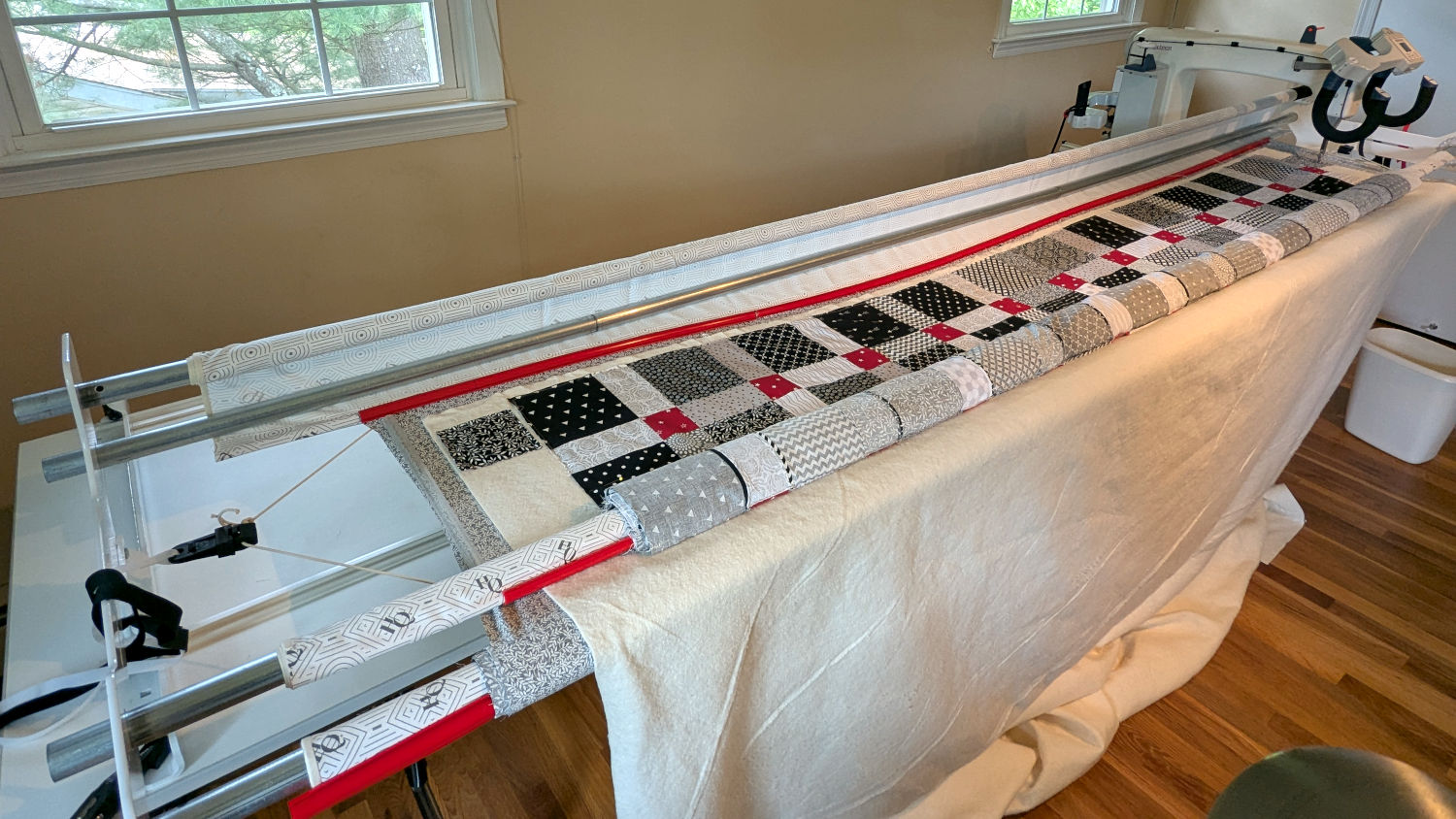
The rods (a.k.a. tubes or poles) holding & guiding the quilt top / batting / backing fabric on Mary’s HQ Sixteen longarm quilting machine span the eleven feet of the table:
HQ Sixteen – table overview
The two end plates are 1/4 inch steel plate with four punched holes for the rods / tubes, which look remarkably like EMT. The machine is two decades old and Mary is (at least) the third owner, so it’s no surprise the rods long ago wore through the white powder-coat paint on the plates and, during the course of a long quilting project, now deposit black dust on the table.
Black dust not being tolerable near a quilt-in-progress, Mary asked for an improvement.
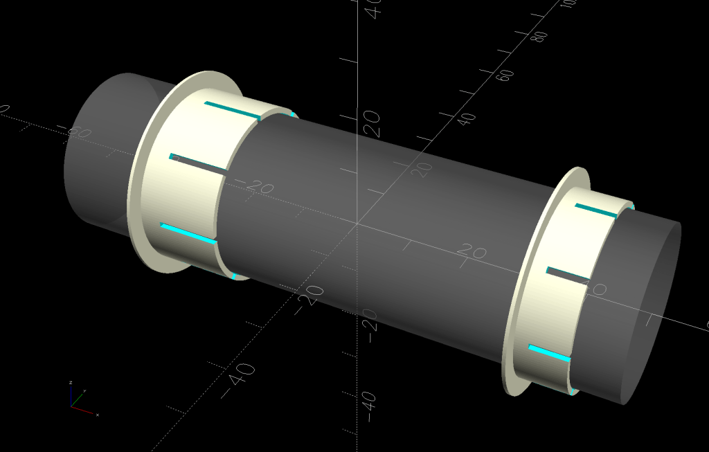
The tube OD is 28.7 mm (so it’s probably 1 inch EMT) and the plate hole ID is 31.2 mm (likely a scant 1-¼ inch punch), leaving barely a millimeter of clearance all around. I wanted to make a bearing from suitably slippery Delrin / acetal, but figured 3D printed PETG would suffice for at least while.
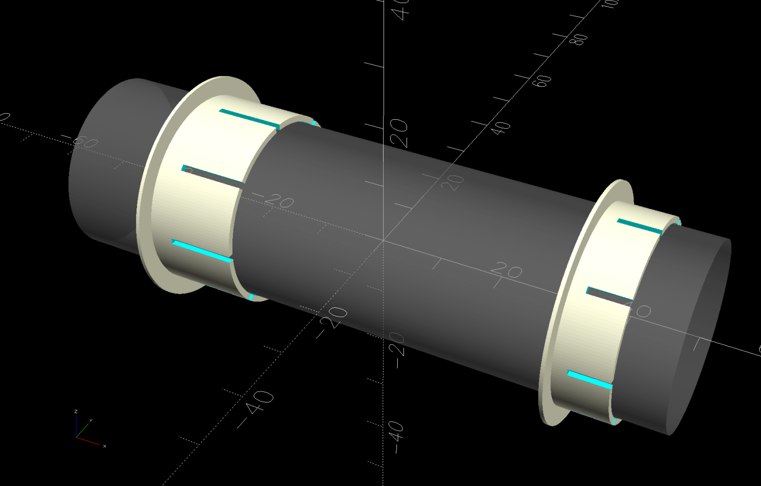
The proper term is “bushing“, because it has no moving parts:
Rod Bearing Sleeve – solid model – show view
On the right side, the bushing rim must fit between the sprockets and the plate:
HQ Sixteen rod – right front
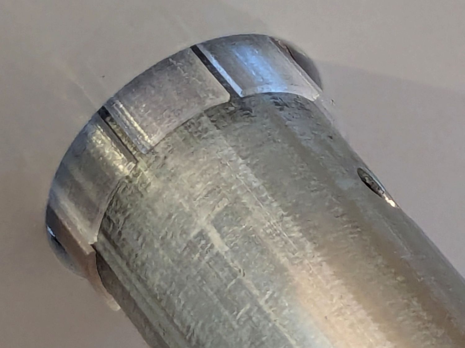
The spring-loaded pin holding the tube in place (visible on the inside bottom) sets the maximum length:
HQ Sixteen rod – right outer
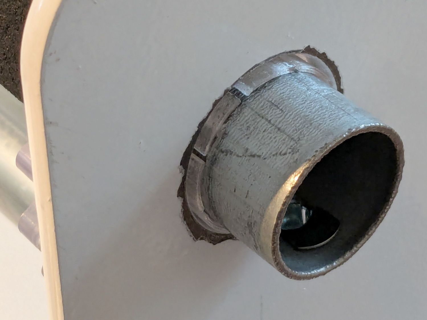
The left side has none of that, so I made the bushings a little longer:
HQ Sixteen rod – left inner
The left-side bushings will need a better design should normal back-and-forth sliding push them out of place.
A touch of silicone grease around the plate holes makes those bushings / bearings turn sooo smooth.
This file contains hidden or bidirectional Unicode text that may be interpreted or compiled differently than what appears below. To review, open the file in an editor that reveals hidden Unicode characters.
Learn more about bidirectional Unicode characters


