Ed Nisley's Blog: Shop notes, electronics, firmware, machinery, 3D printing, laser cuttery, and curiosities. Contents: 100% human thinking, 0% AI slop.
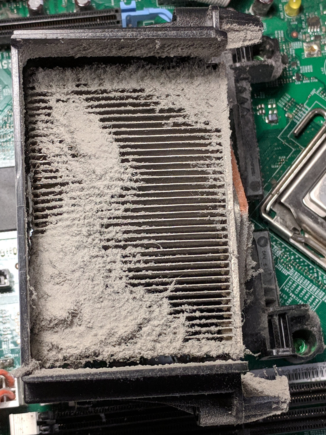
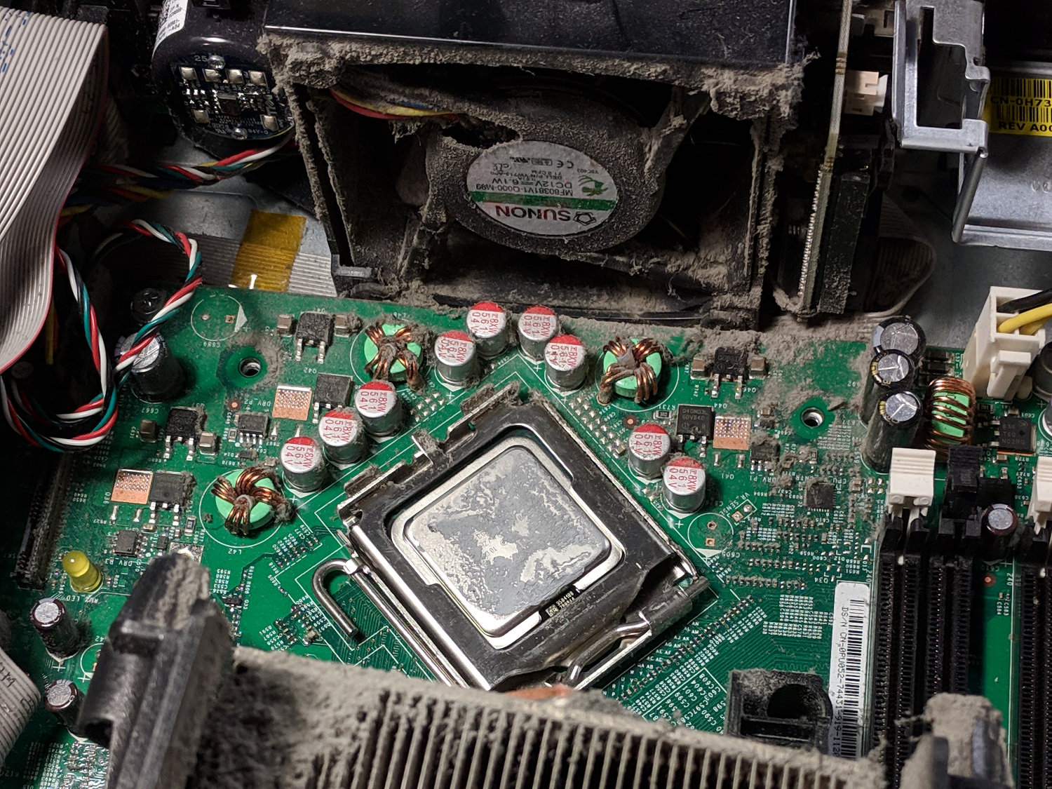
This appeared while harvesting heatsinks and suchlike from a defunct Dell Optiplex:
Clogged CPU heatsink
The only way to get access to that end of the heatsink is to break the heatsink’s thermal bond to the CPU, which seems like a Bad Idea if you intend to continue using the thing:
Problem: Temperature fluctuation on the hotend +/- 7 degrees C when set in the controls. A little more extreme when printing (~+/- 15).
Slow cycling like that indicates the hot end’s PID loop coefficients don’t match reality.
Preheat the extruder to maybe 200 °C, run a PID calibration (M303), store the results in EEPROM (M500), and that should do the trick.
PID coefficients depend on the hot end’s physical condition, so you should re-do the calibration whenever anything changes on the hot end. Even removing & reinstalling the same hardware will change the contact points between, say, the thermistor and its hole in the hot end.
A dab of good heatsink compound on the thermistor should stabilize its contact with the hot end, although that will change the reported temperature and PID coefficients. Probably doesn’t make any real difference, but I felt better:
M2 – Thermistor with heatsink compound
Which prompted a question from a user who regularly swaps entire hot ends to change nozzle diameters:
run a pid cal when I set my starting height each time I switch?
Assuming you swap entire hot ends, including their thermistor & heater, then you can calibrate each one, write down its PID values, manually set ’em with M301 when you install it, then use M500 to store ’em in EEPROM.
Because you bend those fragile thermistor wires every time you swap hot ends, keep a couple thermistors on hand. You’ll need ’em.
You just never noticed the blinkiness before … [grin]
Because the extruder heater is still running, the firmware hasn’t detected a (possibly bogus) thermal runaway or any other fatal problem. It’s just waiting for the next line of G-Code, but Octopi isn’t sending it.
Look at the Octopi Terminal log to see if the conversation just before the failure matches those descriptions.
Assuming you haven’t updated the printer firmware or anything on the Octopi, then something physical has gone wrong.
First and least obviously, the Pi’s MicroSD card has probably started to fail: they’re not particularly durable when used as a mass storage device and “the last couple of years” is more than you should expect. Download a fresh Octopi image, put it on a shiny-new, good-quality card (*), and see if the situation improves.
Then I’d suspect the Pi’s power supply, even though you’re using the “official rpi power supply”. All of those things contain the cheapest possible electrolytic capacitors, running right on the edge of madness, and produce bizarre errors when they begin to go bad. Get a good-quality wall wart (**), ideally with a UL rating, and see if the situation improves.
While you’re buying stuff, get a good-quality USB cable (***) to replace the one that (assuming you’re like me) you’ve been saving for the last decade Just In Case™. Use the shortest cable possible, because longer does not equal better.
After that, the problems get truly weird. Apply some tweakage and report back.
(*) This is harder to do than you might think. You may safely assume all cards available on eBay and all “Sold by X, Fulfilled by Amazon” cards will be counterfeit crap. I’ve been using Samsung EVO / EVO+ cards (direct from Samsung) with reasonable success:
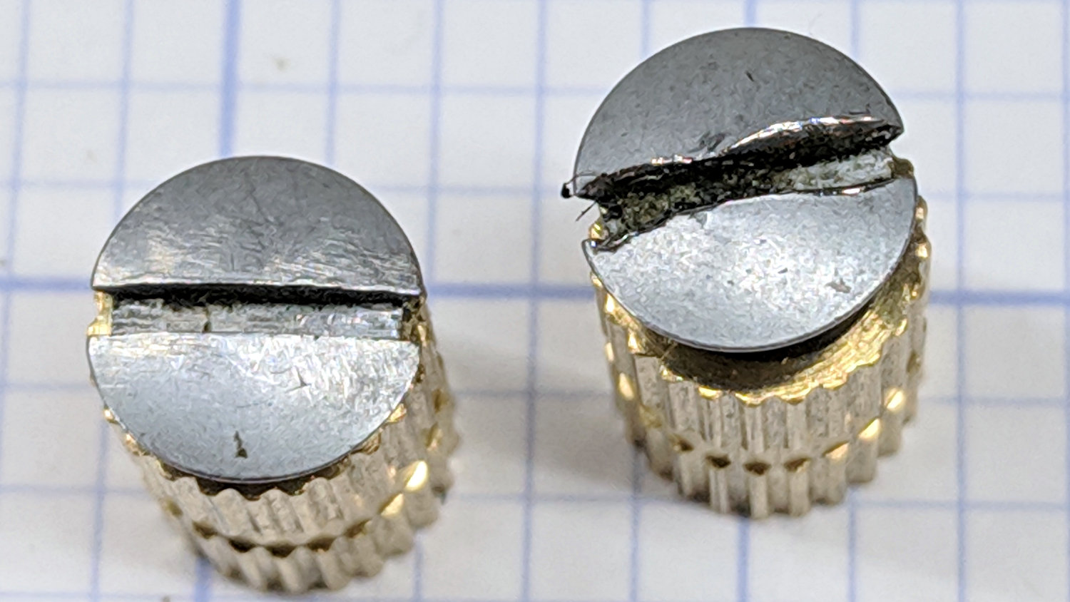
One of Mary’s quilting group arrived with a machine in dire need of cleaning and oiling. These screws hold the throat plate in place:
Kenmore screws – goobered
They’re standing in a pair of threaded brass inserts (found in the benchtop litter) to show off their tops.
The left screw came out easily, although a few licks with a fine file eased the slot corners.
The one on the right, however, was firmly jammed in place, with the crappy little Kenmore sewing machine screwdriver causing the goobering. I deployed my Brownell’s Gunsmith Screwdriver Bits, applied slightly less force than would ordinarily call for an overnight penetrating oil session, got the screw out, and cleaned it up:
Kenmore screws – smoothed
A dot of oil on the threads should keep it happy for the foreseeable future.
The intent was to wire the “5 W” COB LED to the 12 VDC supply grafted on the Juki TL-2010Q, through a suitable resistor around 18 Ω. Unfortunately, the next morning I managed to run 12 V directly to the LEDs, which produced an astonishingly bright flash of blue-white light and an opportunity for some post-mortem analysis.
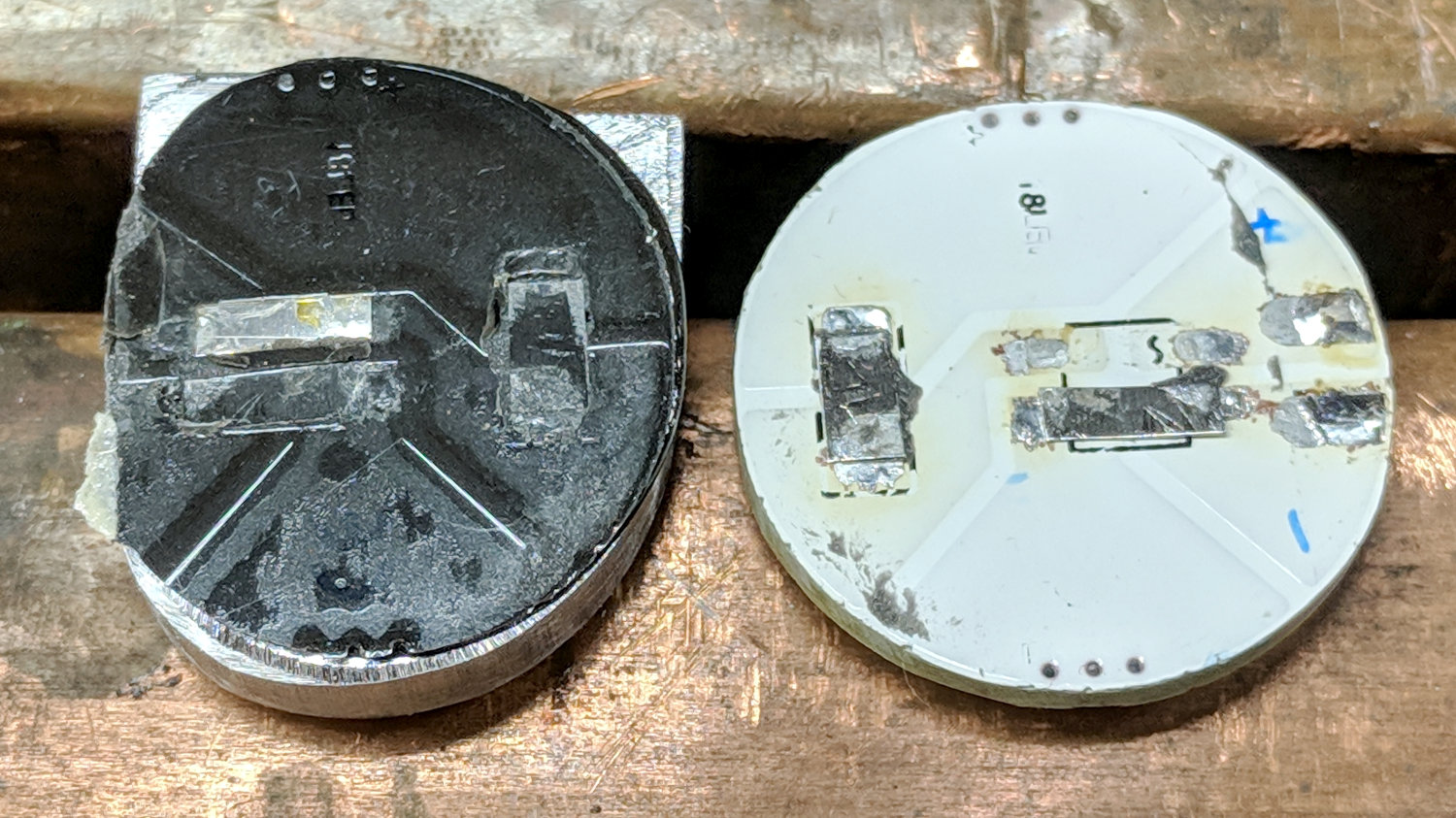
A sharp tap with a chisel popped the COB LED PCB off its heatsink:
Destroyed COB LED – epoxy bond
That’s a pretty nice thermal joint and ought to transfer as much heat as reaches the back surface. Mechanically, it yanked one of the nickel tabs right off the solder pads; obviously, I must now level up my soldering game.
Scraping the yellow silicone filter off the PCB reveals the minuscule LEDs:
Destroyed COB LED – excavated yellow silicone
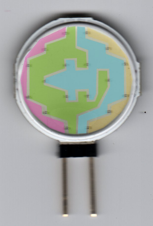
You’ll recall they’re arranged in three series sets of six:
Circular 12V COB 18 LED panel – copper layout
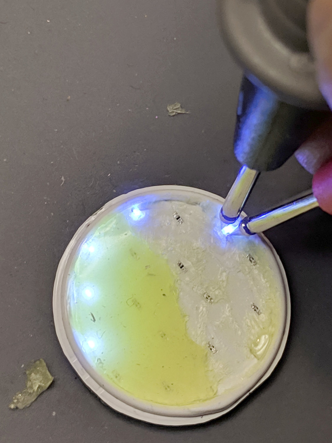
Some probing revealed five of six LEDs in one set was still functional:
Although a few other LEDs across the PCB survived, that’s not the way to bet when you run so much current through the poor things.
Ah, well, that’s why I always buy a few more parts than I really need …
With more snow on the schedule, Mary’s bike finally got a new rear shifter:
Tour Easy – SRAM X.0 grip shifter installed
It’s an old-school SRAM X.0 grip shifter, evidently compatible with SRAM X.9 and X.7 derailleurs, and seems to work OK. The wavy ridges may be more prominent than necessary for our road riding, though.
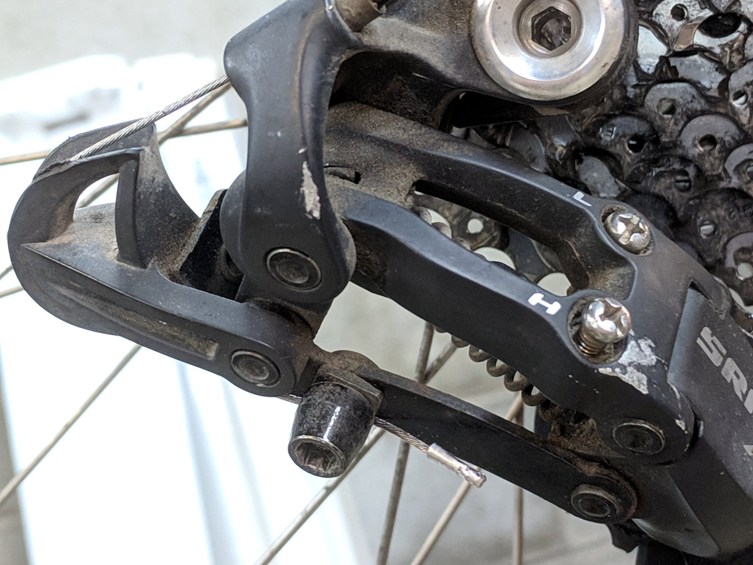
In a miracle of rare device, the preinstalled cable turned out to be exactly long enough:
Tour Easy – SRAM X.0 cable length
Twiddling the length for perfect shifting requires on-the-road testing and the chain wrap may need tweaking (I may not have gotten it right when I installed the derailleur), but at least the shifter stops at every detent along the way.
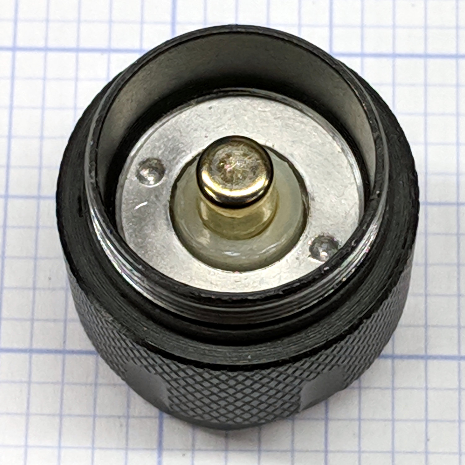
Mashing the LED PCB into place didn’t entirely solve the weak beam problem, so I unscrewed the tailcap holding the switch on the other end of the body:
J5 Tactical Flashlight – tailcap
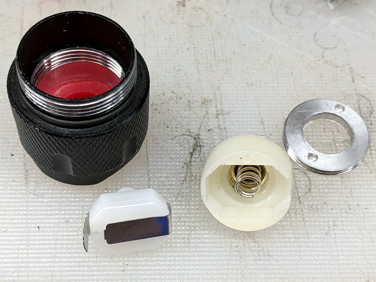
Unscrewing the lock ring releases the switch assembly:
J5 Tactical Flashlight – tailcap parts
I suspect the tab sticking out from the side of the switch doesn’t make / never made good contact with the aluminum tailcap body, but having gone this far there’s no reason to stop. The plastic housing around the spring-loaded brass battery contact pops off to reveal the actual switch:
J5 Tactical Flashlight – switch contacts
The long tab on the front of the switch sits under the spring, so that’s the negative battery contact. The LED current goes through:
battery negative to contact + spring
switch tab + moving contact + tab
tab to tailcap pressure fit
tailcap threads
front tube threads
LED pill to PCB
spring to battery positive
So. Many. Aluminum. Joints.
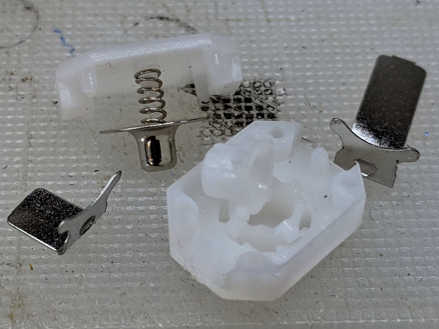
The switch body snaps apart to disgorge a remarkable number of parts:
J5 Tactical Flashlight – tailcap switch parts
Nothing looked out of order, so I applied a thin layer of DeoxIT Red to all the contacting parts and reassembled everything.
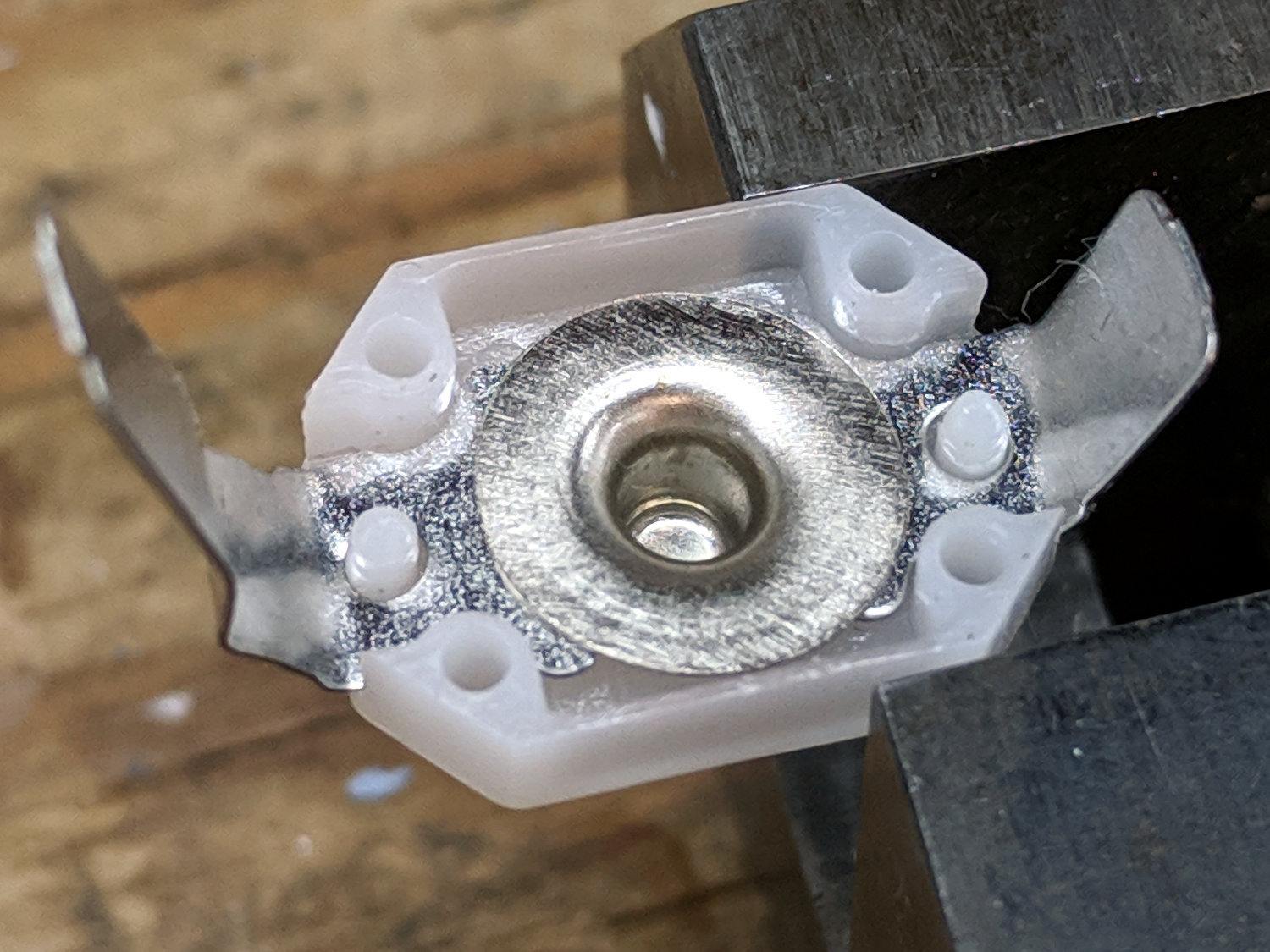
For the record, the switch’s internal parts have many plausible assembly sequences; the workable one goes a little something like this:
J5 Tactical Flashlight – tailcap switch contacts
Contrary to what you (well, I) might think, the switch is off when the central contact is pushed forward, away from the side contacts.
I bent a slight angle into the tailcap contact (on the right in the picture) to make better / firmer contact with the tailcap body, cleaned all the threads with a cotton swab carrying a dab of DeoxIT, and screwed it all together.
With everything back together, the beam seems bright and steady again. We’ll see how long it lasts.