Over the next several days, I’ll be screwing around with trying out different blog themes, because WordPress has “deprecated” the theme I’ve been using since about 2011; it no longer works well with their most recent infrastructure. There being no way to tell how any given theme will look, how difficult creating posts may be, or (in truth) anything about a theme without actually running it, I’ll be doing live-fire exercises while posting odds-n-ends projects from the shop.
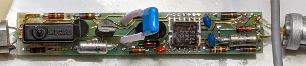
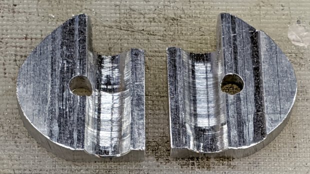
Some themes strongly suggest require a logo, so you’ll see this monstrosity until something better comes along:
Speaking of themes, you’re looking at a “free” blog on wordpress.com, not something I’ve conjured by installing the open-source blog infrastructure from wordpress.org on a server, which means few things you (think you) know about a “WordPress blog” apply. In particular, free blogs on wordpress.com lack access to the universe of themes & plugins applicable to a DIY FOSS installation.
(I think) I’d be perfectly happy to compose posts in Markdown (or some such) and slam them into a static site generator (Hugo / Gatsby / whatever), rather than slog through WP’s GUI editor, but I think my usual post-a-day pace conflicts with the fundamental assumptions of a “static site” generator.
I value blog comments from real people (you all know who you are and I thank you!), but blogspam presents a clear & present danger. Right now, Akismet kills nearly all the hundreds of spam comments per day; it’s obvious any blog comment system must include robust spam filtering. The alternative of, say, running a separate email list for comments seems far more trouble than it’s worth.
I absolutely do not want to sysop my very own blog configuration on a rented server / VPS / Digital Ocean Droplet / whatever. Things like WPengine.com would be attractive, except that this blog’s very long tail generates enough traffic to come very close to the 25 k visit/month upper limit of their “startup” plan; I’m reluctant to pay $100/month for the 100 k visit/month “growth” plan just to host my shop notes.
If you have recommendations / experience / horror stories concerning FOSS blogging software, add a comment or send me a direct note through the form at the bottom of the misleadingly titled “About” page.
For the next few days, remember: there is nothing wrong with your television set.