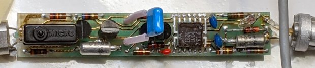
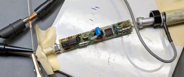
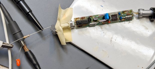
When I re-capped the HP 10525T Logic Probe, I expected the matching HP 10526T Logic Pulser would require the same treatment. Having finally gotten a Round Tuit, I preemptively pulled it apart to see what was going on inside:
The manual includes the schematic, of course:
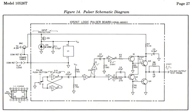
The IC is a Motorola SN7404 Hex Inverter sporting an HP house number in a ceramic flatpack: pin 1 in the upper right, VCC on pin 4, and common on pin 11. The 7716 datecode suggests the chip first saw daylight shortly after single-chip microcontrollers became a nontrivial thing.
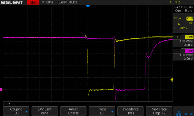
The pushbutton switch triggers the expected pulses at pins 10 (purple) and 12 (yellow), with timings controlled by the RC networks:
The collector output of Q2 is a robust 73 mA pulse through its 62 Ω resistor:
Q1 dumps 15 mA into its 300 Ω resistor:
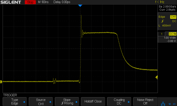
The push-pull output at the emitter of Q3 and the collector of Q4 looks similar (albeit with some delay cranked in to show the tidy exponential tail):
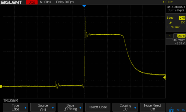
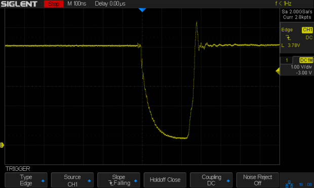
The manual specifies a 3.0 Ω resistor to ground for Test A, thusly:
The output peaks at nearly 3 V to drive a robust 1 A (!) pulse:
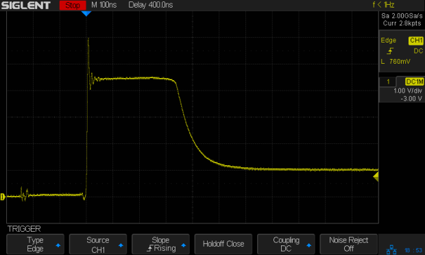
Test B requires a 6.2 Ω resistor driven from 5 V, but a 6.8 Ω resistor came to hand:
The downward pulse doesn’t quite reach 0 V (because saturation voltage, etc), so it’s a mere 725 mA:
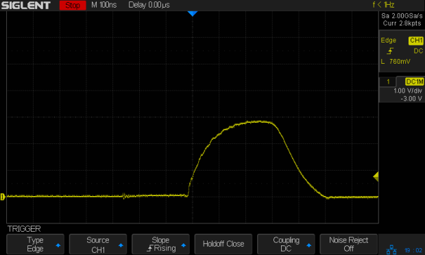
HP’s formal setup for Test C requires a totalizing counter to show the pulser produces exactly one pulse for each button push. I just wired up a 47 Ω resistor and eyeballed a few pulses:
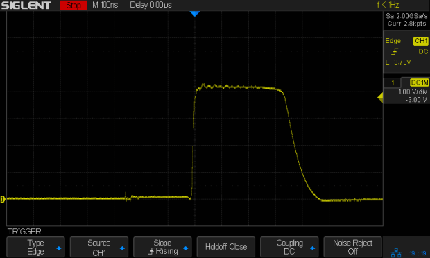
The lighter 85 mA load through the resistor allows a more rectangular pulse than the 3 Ω resistor. Yup, looks clean to me.
Because the pulser drives its output both low and high with great authority, it doesn’t care what state the external net wants. Here’s what happens with the 47 Ω resistor connected to a 2.5 V supply:
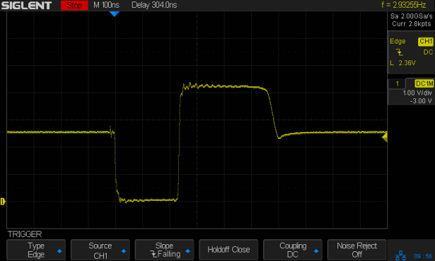
No matter where the logic family’s threshold might be, the net will experience one downward and one upward transition through it: with the pulser delivering nigh onto an amp, the net’s driver doesn’t stand a chance.
However, the pulser was designed for TTL and DTL (remember DTL?) circuitry, so hammering a 3.3 V microcontroller pin probably isn’t a Good Idea. The notion of keeping a pulser around Just In Case may have reached its end times.
Oh, and about the re-capping. Turns out HP used solid tantalum capacitors and they’re still doing fine after four decades, thankyouverymuch. I put it back together and expect it will continue working forevermore.
