Ed Nisley's Blog: Shop notes, electronics, firmware, machinery, 3D printing, laser cuttery, and curiosities. Contents: 100% human thinking, 0% AI slop.
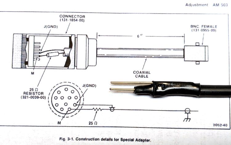
The Tektronix AM503 manual specifies a Special Adapter to inject a signal directly into the input connector in place of the A6302 Hall probe:
Tektronix AM503 Special Adapter
The intricate Amphenol plug might still be available at some phenomenal cost, but I’m willing to just jam a pair of wires into the AM593 connector and be done with it.
I combined a pigtail BNC sporting a male connector, two 51 Ω resistors in parallel, two snippets of 18 AWG wire (an exact match for the 40 mil connector pins!) with the ends filed smooth, and some heatshrink tubing to make a roughly equivalent adapter:
Tek AM503 – Crude Special Adapter
Because the pigtail didn’t quite reach the function generator, I joined it to a longer cable with a BNC bullet, whereupon a slight tug ripped the guts out of the bullet:
BNC Bullet – failed
A closer look:
BNC Bullet – parts
The center hole comes into play with their equally craptastic BNC tee connectors.
Comparing this bullet with others from the same eBay lot shows the outer shell didn’t get quite enough crimp around the metal ring. Because it’s not an electrical connection, I eased some epoxy onto the internal shoulder where that ring seats, then slid the guts back in place.
So, despite it not showing any leakage or damage, I replaced C155:
Tek AM503 B075593 – C155
Which had stopped being a capacitor some time ago:
Tek AM503 B075593 – C155 measurement
I also replaced C165 with a newer capacitor.
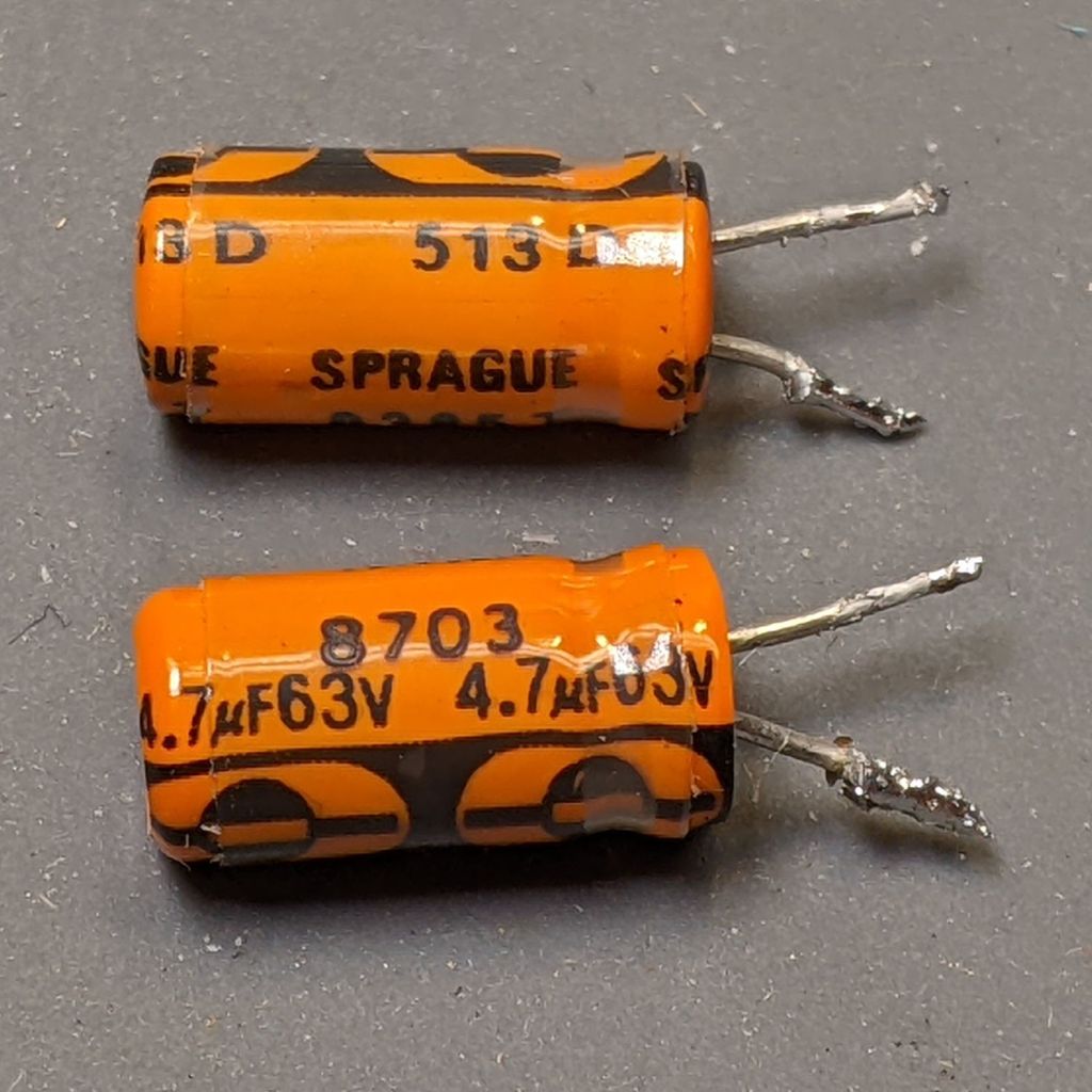
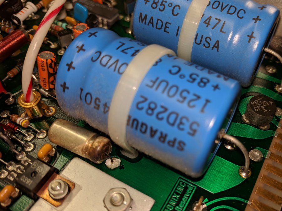
Again, having the hood up, I pulled C452 and C462 from the ±19.3 V supplies:
Tek AM503 B075593 – C452 C462
Despite the 1987 date code, they seemed to be in fine shape, but I replaced them anyway. The new caps have a 50 V rating, not the original 63 V: only a factor of two headroom.
The four new capacitors in their new home:
Tek AM503 B075593 – replaced caps
The power supply voltages looked clean before and look clean now.
The AM503 still has the mysterious 4 MHz oscillation, so the capacitors weren’t the problem. Even though the amp is still sick, I feel better.
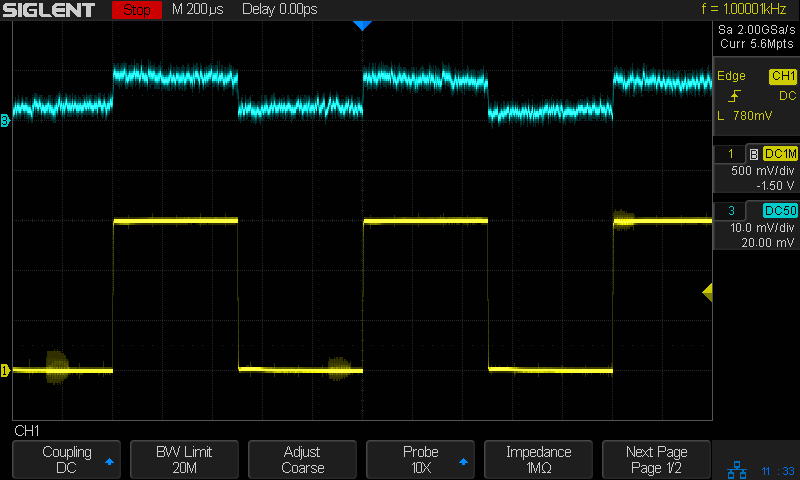
The test signal (yellow) comes from the scope’s calibrator output into a 2320 Ω resistor, so the AM503 calibration is about right: 0.6 mA ≅ 1.5 V/2320 Ω.
Just to maintain historical accuracy in the two AM503 amps in the TM502 mainframe on the Electronics Workbench, I transplanted the good (not noisy) OEM Tek Q230 (from SN B075593) into the previously noisy-and-offset-prone AM503, which now works fine. I now have a pair of works-pretty-good AM503 amps, one not-so-good AM503 in the to-be-fixed lookaside buffer, plus a defunct Q230 dual JFET.
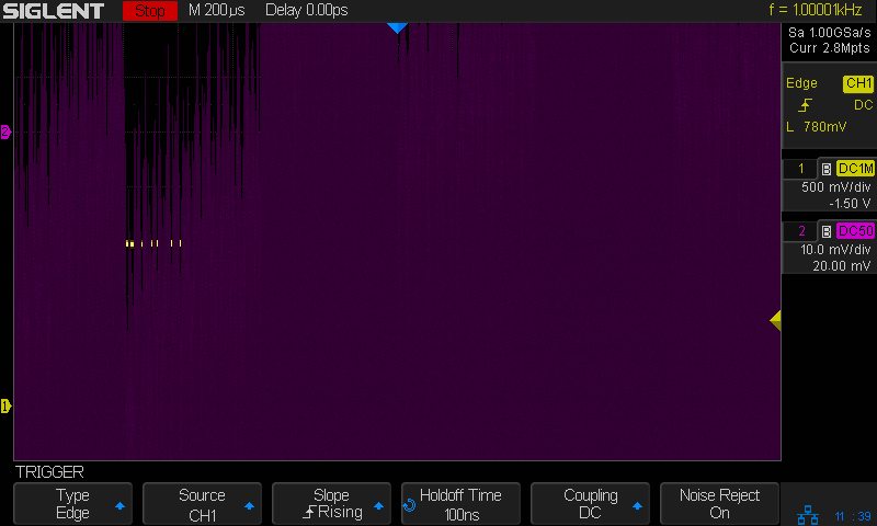
That third amp (B075593, now with the NOS 2N5911) has a nasty noise problem:
Tek AM503 B075593 – SDS2304 cal – 1 mA-div
The barely visible yellow trace is the same calibrator signal as before, but the output is a howling 4.2 MHz (!) sine wave. The oscillation amplitude responds to the AM503 front panel gain control, making it possible to see what’s going on:
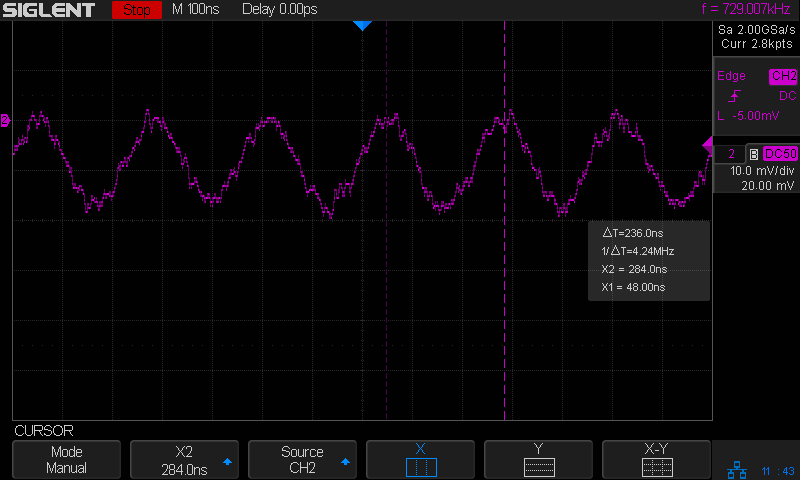
Tek AM503 B075593 – 4 MHz oscillation
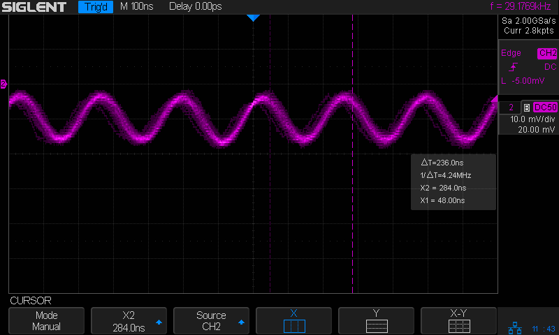
Flipping the front panel switch to limit the AM503 bandwidth to 5 MHz shaves off the fur:
Tek AM503 B075593 – 4 MHz osc – 5 MHz BW
Disconnecting the probe or unplugging P220 kills the oscillation, as does setting the front panel switch to CAL/DC LEVEL, which means it’s an internal feedback problem.
It’s trivially easy to construct an amplifier circuit that becomes an oscillator at the slightest provocation, but this puppy had been working dependably for somebody else during the three decades (!) before I bought it and continued for a few years after that, so the overall circuit topology is known-good.
Shooting this one will require more pondering, as the obvious first step of replacing the power supply’s electrolytic caps had no effect.
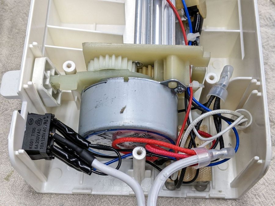
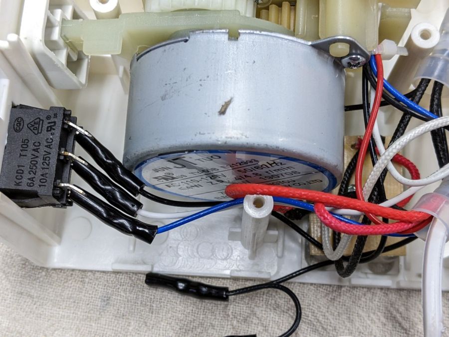
Someone with a jammed Amazon laminator inadvertently dislodged the switch wiring, so I took a few more pictures to help. Note: I see absolutely no reason to assume any two laminators will have the same wire colors, but the overall functions should be the same.
The top set of three switch terminals control the overall power to the laminator:
Amazon Laminator – switch wiring
The center terminal comes from the unmarked (no ridges) wire in the line cord. The two outer terminals are connected together with a short jumper from the terminal nearest the motor, with a longer black wire to the wire nut binding other black wires.
The bottom set of terminals select the temperature:
Amazon Laminator – switch bottom contacts
The white wire on the center terminal goes to the wire nut holding the other white wires and a black wire (!) going to the middle of the three thermostats on the extrusion. The black and blue wires on the outer switch terminals go to the thermostats on the aluminum extrusion to the heater.
Verily, it is written: There’s nothing like a good new problem to take one’s mind off all one’s old problems.
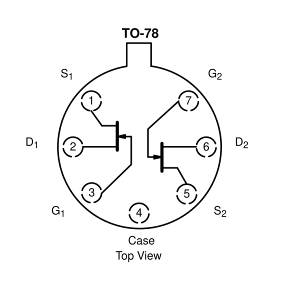
Some suggested 151-1032-00 replacements obviously won’t work, such as Tekwiki’s 2N5397 single JFET. Bonding a pair into a single heatsink might suffice, but two separate cans generally aren’t identical enough for the purpose.
Curiously, Tekwiki also lists the 2N5911 as a 151-1032-00 replacement, which (being an actual dual JFET) looks more promising. This agrees with another cross-reference, although the “Sim[ilar] to” suggests considerable caution.
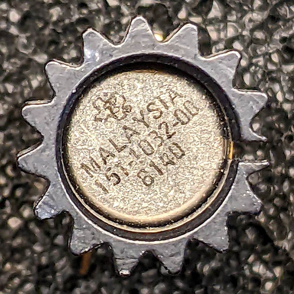
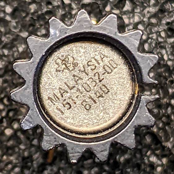
The actual Tek 151-1032-00 can in its heatsink, oriented with the tab at the top (just visible to the right of the heatsink fin):
Tek 151-1032-00 – top view
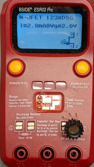
Testing one side (with the tab on the left):
Tek 151-1032-00 test side A
And the other side (tab still on the left):
Tek 151-1032-00 test side B
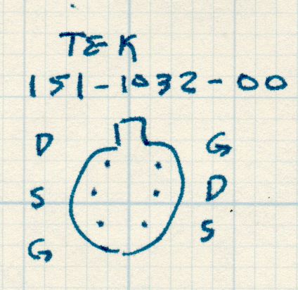
A picture being worth a kiloword:
Tek 151-1032-00 – measured pinout
The drain and source over on the left side seem to be swapped compared to the 2N5911, although both gates are on the proper pins. This being a JFET, the source and drain may be electrically identical and it’s possible the tester labelled them backwards. The only way to be sure Tek wasn’t tragically clever is to poke around the PCB to figure out which pins connect to which other components.
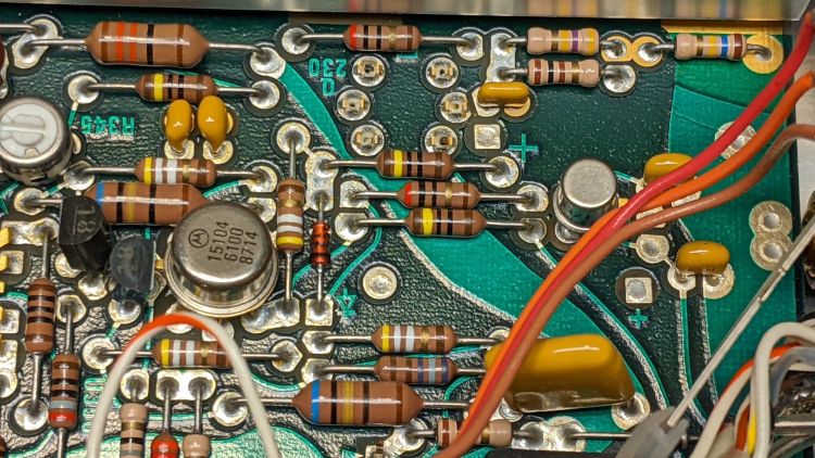
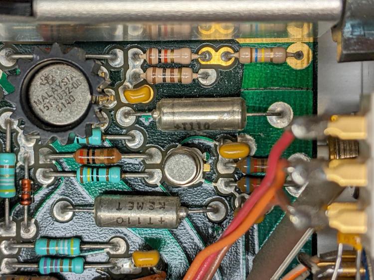
So take a picture of the component neighborhood around the Q230 sockets:
PXL_20220105_210538214
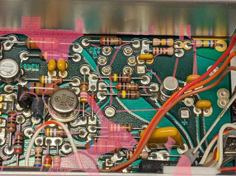
Overlay it with a similar picture of the solder side, suitably reversed / recolored / transformed to match:
Tek AM503 – 151-1032-00 area – X-ray traces
The copper-side traces aren’t complete, as the red coloring marks only traces under the soldermask and omits bare solder-coated traces. Some traces on the component side run invisibly under parts. If I were doing it for money, not love, I’d pay more attention to the details.
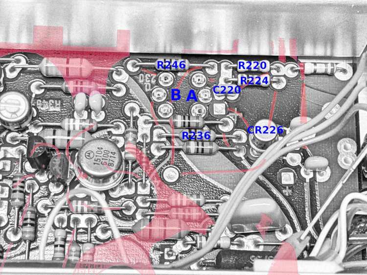
Devote some time to tracing the traces and labeling the parts:
Tek AM503 – 151-1032-00 area – part IDs
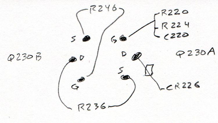
Then doodle out the actual connections:
Tek 151-1032-00 – part connections
R246 shows Q230B lives in the left side of the can, because it’s connected between the B gate and B source pins, and confirms the tester swapped the B source and B drain pins. Whew!
R236 connects the B drain and the A source, confirming the pinout matches the 2N5911.
Comfortingly, the A side gate goes to all those other parts as it should.
So a 2N5911 will drop right into the Q230 socket with the proper pins going to the proper places. Whether it’s electrically Close Enough™ to the Tek spec, whatever it might have been, remains to be seen, but a good transistor circuit won’t depend too much on the actual transistor parameters.
The fact that changing R220 also changed the noise should have pinpointed the noise source, but such things are always more obvious in retrospect than in real time running. This post should help me start the next debugging spree a bit further up the learning curve.
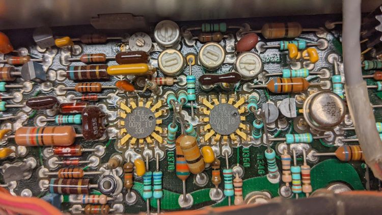
The AM503 signal path includes a pair of … unique … differential amplifier ICs made by Tektronix back in the early days of integrated circuitry:
Tek AM503 – U370 U350 detail
The picture has the signal flowing right-to-left through U350 and U370, starting with the Q310 dual NPN in the metal can and the Q315/325 PNP pair (both over on the right side near the cable).
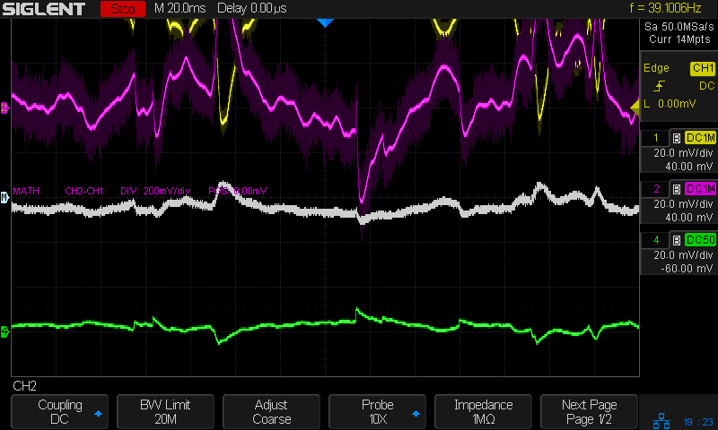
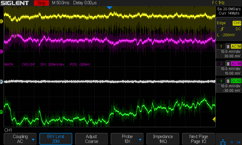
Anyhow, the differential output of U370 shows the noise across pins 6 and 8 (yellow and magenta):
Tek AM503 – diff output U370.6-U370.8
Again in retrospect, pins 9 and 5 would have been a better choice.
The white line is the difference between the two pins and resembled the scope output in the bottom trace well enough to satisfy me.
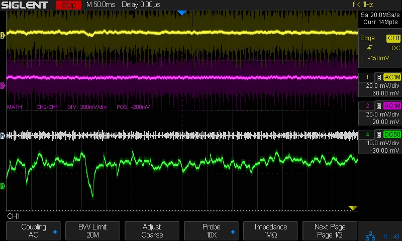
The differential input to U350 on pins 16 and 14 also shows a distinct similarity to the output noise:
Tek AM503 – diff input U350.16-U350.14
It’s essentially impossible to snap a scope probe around those IC pins, but merely extraordinarily difficult to securely grab the tails of the pin sockets extending beyond the solder side of the PCB.
Finally, a look across R317, the emitter resistor between the halves of Q310:
Tek AM503 – diff input – R317
That was enough to finally convince me the problem lay upstream of Q310.
Ruling out the DC level pot required balancing another AM503 atop this one to plug its cable into the PCB, which showed same output noise.
Hat tip to Sherlock Holmes:
“When you have eliminated all which is impossible, then whatever remains, however improbable, must be the truth.”
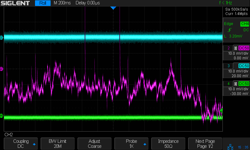
Because Q230 is socketed, I pulled it out and popped it into another AM503, whereupon the noise followed the transistor:
Tek AM503 – three amps – GND
All three AM503 amps are set to GND / DC LEVEL CAL. The cyan trance is the formerly noisy amp (now with a good Q230), the magenta trace is the formerly good amp (now with the bad Q230) , and the green trace is the best of the three AM503 amps (untouched, for well and good reason) in my collection.
One of my Tek AM503 current probe amplifiers (SN B064098) suffered from DC offsets in the AC / GND / DC modes, to the extent that zeroing the GND (more formally known as “CAL DC LEVEL”) offset wouldn’t keep the other two baselines on the scope screen. Kibitizing with another AM503 owner with a different problem clued me to apply a change made in later units: replace the 1 kΩ resistor at R220 with a 470 kΩ resistor to reduce the source impedance changes between the switch positions:
AM503 – R220 change
For the record, R220 sits parallel to the attenuator shield above and to the right of Q230 (in the black clip-on heatsink):
Tek AM503 – R220 detail
The new resistor somewhat reduced the offset problem, but also dramatically increased the noise level I’d been studiously ignoring, to the point where the AM503 output was unusable:
Tek AM503 – three amps – GND
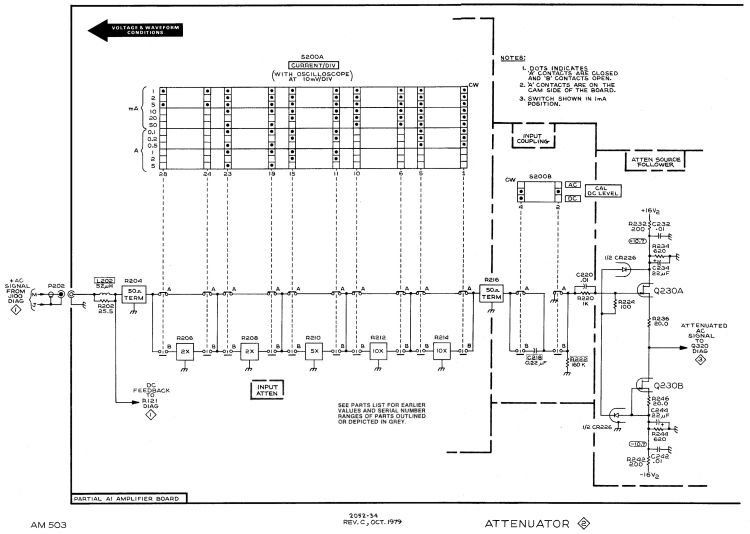
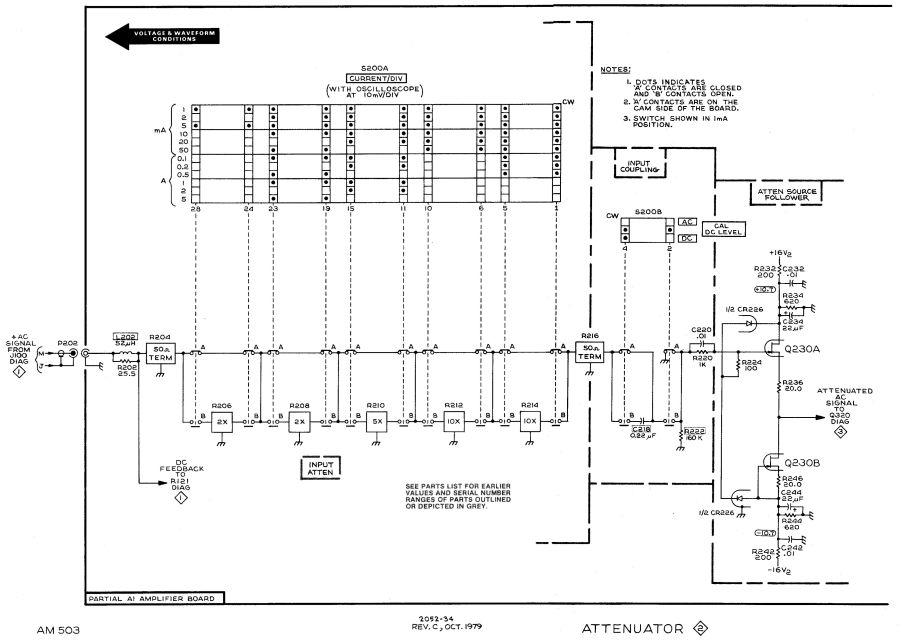
The rule of thumb is that it’s always a connector or, perhaps, a similar metallic contact in the signal path. The AM503 has a breathtakingly aggressive switched attenuator covering the 94 dB range from 1 mA/div to 50 A/div:
The switches are cam-driven bifurcated gold-plated spring fingers contacting gold-plated PCB pads under that aluminum shield:
Tek AM503 – Attenuator Contacts – detail
The spring-loaded thing to the right is R206, the first 50 Ω 2× attenuator in the form of thin-film elements fired on a ceramic substrate. The two switches put C218 into the signal path in AC mode.
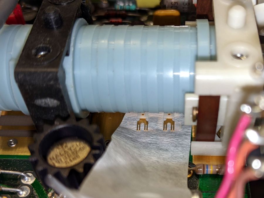
You (well, I) clean the fingers by very gently pulling a strip of lens cleaner moistened with isopropyl alcohol through the closed contacts:
Tek AM503 – Attenuator Contact Cleaning
The pale blue cylinder is the attenuator cam roller extending across the PCB behind the front-panel knob. The two switches bypass C218 in DC mode and connect R220 to ground in GND mode.
Clean gold-on-gold contacts are about as good as it gets and those things looked absolutely pristine. After wiping the contact connecting R220 to ground had no effect, it finally penetrated my thick skull that the problem wasn’t in the attenuator contacts and had to be downstream in the amplifier and filter chain.
Reseating all the cable connectors and jostling the (socketed!) semiconductors also had no effect.
Could one of the semiconductors have gone flaky after four decades?