The Smell of Molten Projects in the Morning

Ed Nisley's Blog: Shop notes, electronics, firmware, machinery, 3D printing, laser cuttery, and curiosities. Contents: 100% human thinking, 0% AI slop.

Tag: Repairs

If it used to work, it can work again

  • HP Scope Probe Flange Repair: Improved Spares

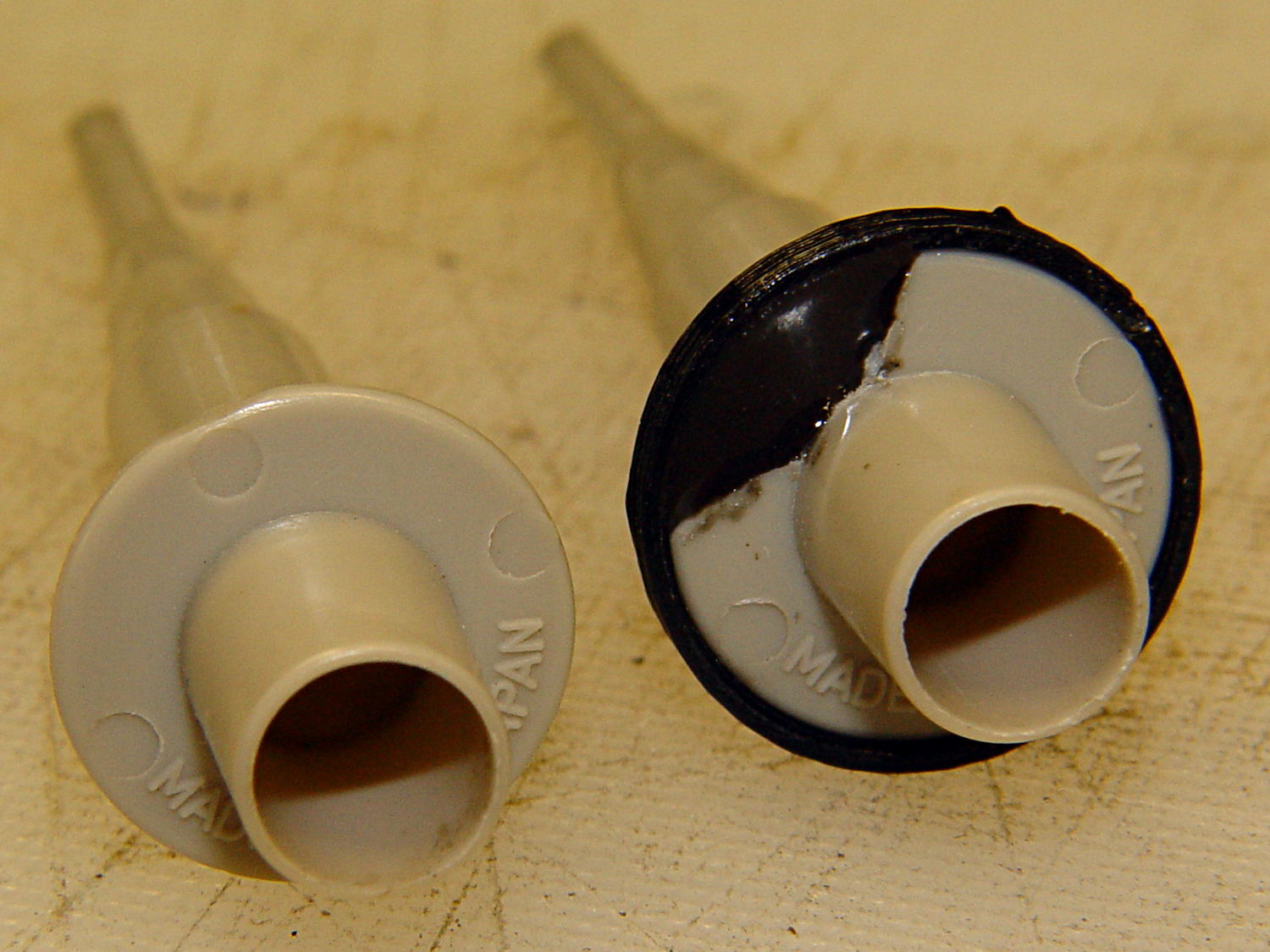
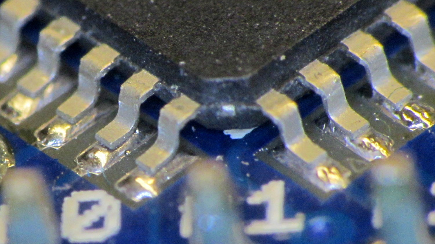
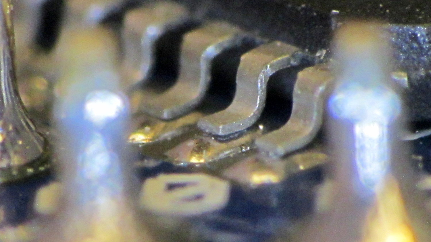
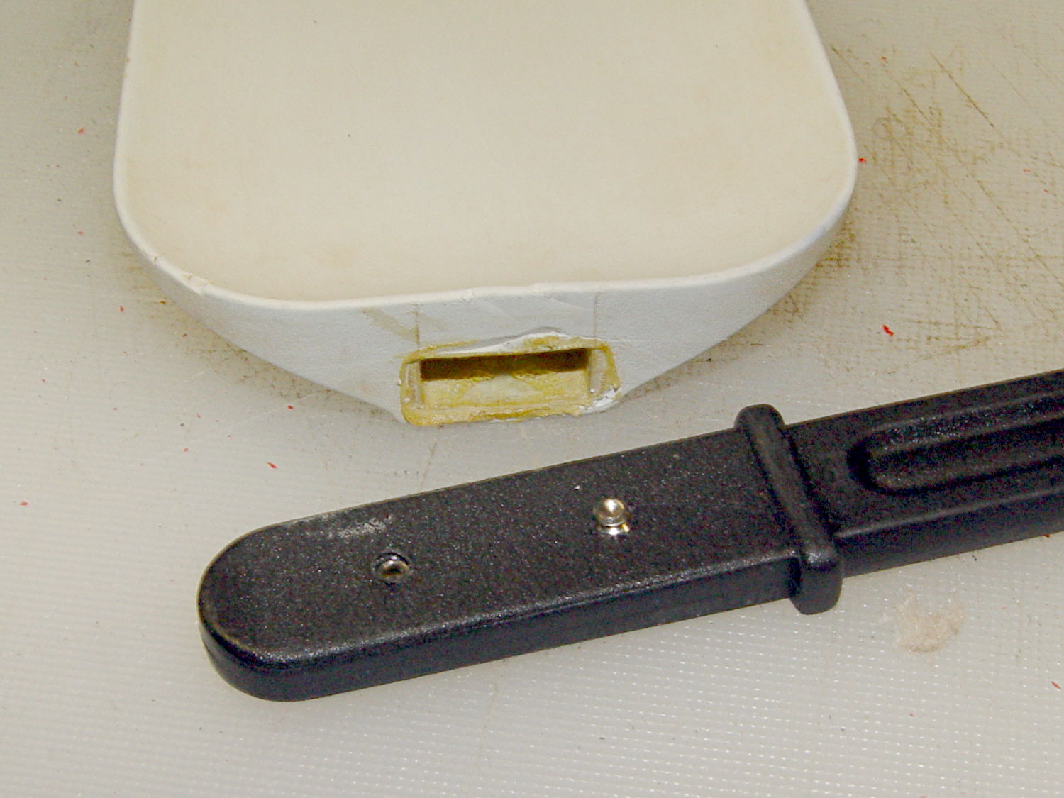
    While reducing the clutter atop the Electronics Workbench, I ran off four more probe flange reinforcements, just so I’m ready for the next crunch:

    HP scope probe flange disks
    HP scope probe flange disks

    They’re almost identical to the previous version, although I tweaked the taper to end slightly inside the cylindrical cup, thereby eliminating the coincident faces and leaving a minute rim that doesn’t matter:

    HP Scope Probe Flange Repair - bottom
    HP Scope Probe Flange Repair – bottom

    Given that I’ve had the ‘scope for nigh onto two decades and have only broken one probe flange, I think four reinforcements will be a lifetime supply: with any luck, the scope will blow a capacitor before I do.

    The OpenSCAD source code:

    // Tek Scope Probe Flange
    // Ed Nisley KE4ZNU November 2013
    
    //- Extrusion parameters must match reality!
    //  Print with 2 shells and 3 solid layers
    
    ThreadThick = 0.20;
    ThreadWidth = 0.40;
    
    HoleWindage = 0.2;
    
    Protrusion = 0.1;            // make holes end cleanly
    
    function IntegerMultiple(Size,Unit) = Unit * ceil(Size / Unit);
    
    //----------------------
    // Dimensions
    
    FlangeOD = 16.0;
    FlangeID = 8.75;
    FlangeThick = IntegerMultiple(1.25,ThreadThick);
    
    DiskOD = FlangeOD + 4*ThreadWidth;
    DiskThick = FlangeThick + 4*ThreadThick;
    
    NumSides = 8*4;
    
    //----------------------
    // Useful routines
    
    module PolyCyl(Dia,Height,ForceSides=0) {            // based on nophead's polyholes
    
    Sides = (ForceSides != 0) ? ForceSides : (ceil(Dia) + 2);
    
    FixDia = Dia / cos(180/Sides);
    
    cylinder(r=(FixDia + HoleWindage)/2,
    h=Height,
    $fn=Sides);
    }
    
    module ShowPegGrid(Space = 10.0,Size = 1.0) {
    
    Range = floor(50 / Space);
    
    for (x=[-Range:Range])
    for (y=[-Range:Range])
    translate([x*Space,y*Space,Size/2])
    %cube(Size,center=true);
    
    }
    
    //----------------------
    // Build it
    
    ShowPegGrid();
    
    difference() {
    union() {
    translate([0,0,2*ThreadThick])
    cylinder(r=DiskOD/2,h=DiskThick,$fn=NumSides);    // cylinder around flange
    
    cylinder(r1=(DiskOD - 2*ThreadWidth)/2,                // flange reinforcing plate
    r2=DiskOD/2,
    h=(2*ThreadThick + Protrusion),
    $fn=NumSides);
    }
    translate([0,0,(DiskThick - FlangeThick)])                // flange clearance
    PolyCyl(FlangeOD,2*FlangeThick,NumSides);
    
    translate([0,0,-DiskThick/2])                            // probe nose clearance
    PolyCyl(FlangeID,2*DiskThick,NumSides);
    }
    
  • Recoil Starter Lube

    This being leaf season, I just discovered that the recoil starter on the hulking 8 HP tangential leaf blower retracts very, very slowly. Having already started the engine, I did one pass around the yard with the pull cord dangling over the handlebar, but that’s not to be tolerated.

    The starter mounts on the back of the motor with five screws, so removing it posed no problem at all. Removing the central screw released the friction clutch that helps extend the pawls, exposing the central boss that’s the combination hold-it-all-together point and gritty bearing for the rope spool:

    Leaf blower recoil starter
    Leaf blower recoil starter

    Pulling the rope turns the spool and extends the pawls that engage the crankshaft. After the motor starts, the pawls retract and none of that stuff moves, so there are no high-speed bearings and not much need for strength.

    I brushed off some of the larger chunks, worked machine oil around the central post, wiped off & lubed the pawls, took the friction clutch apart & lightly lubed it, put everything back together, and the starter now works fine again; there may be too little friction in the clutch, but that’s in the nature of fine tuning.

    The leaf blower Came With The House™ and dates back to the era when Kohler made cast-iron engine blocks. It runs lean on the oxygenated fuel that’s mandated for Dutchess County these days, so it now runs lightly choked.

    Tip: before you yank the rope on a small engine, pull it slowly until the crankshaft stops turning freely, then let the rope retract. That positions the piston at the start of the compression stroke with the valves closed, so your next full-strength yank will do the most good.

  • HP Scope Probe Flange Repair

    Quite some time ago I manage to break the finger flange on one of my scope probes and, what with it being made of an un-glueable engineering plastic, a simple repair job failed quickly. It’s entirely round and a perfect lathe project, but … this is easier:

    HP Scope Probe Flange Repair
    HP Scope Probe Flange Repair

    You can see remnants of that failed repair just below the fracture:

    HP scope probe flanges - repair disk
    HP scope probe flanges – repair disk

    Some epoxy around the rim of the flange, plus filling the missing sector, looks about as grubby as you’d expect:

    HP Scope Probes - rear
    HP Scope Probes – rear

    That’s a tiny zit at about 1 o’clock which came off with fingernail pressure.

    From the business end, it actually looks pretty snappy:

    HP Scope Probes - front
    HP Scope Probes – front

    I’m mildly tempted to preemptively reinforce the other probes…

    The OpenSCAD source code joins two parts with coincident faces, but it worked out OK for once:

    // Tek Scope Probe Flange
    // Ed Nisley KE4ZNU November 2013
    
    //- Extrusion parameters must match reality!
    //  Print with 2 shells and 3 solid layers
    
    ThreadThick = 0.25;
    ThreadWidth = 0.40;
    
    HoleWindage = 0.2;
    
    Protrusion = 0.1;			// make holes end cleanly
    
    function IntegerMultiple(Size,Unit) = Unit * ceil(Size / Unit);
    
    //----------------------
    // Dimensions
    
    FlangeOD = 16.0;
    FlangeID = 8.75;
    FlangeThick = IntegerMultiple(1.25,ThreadThick);
    
    DiskOD = FlangeOD + 4*ThreadWidth;
    DiskThick = FlangeThick + 4*ThreadThick;
    
    NumSides = 8*4;
    
    //----------------------
    // Useful routines
    
    module PolyCyl(Dia,Height,ForceSides=0) {			// based on nophead's polyholes
    
      Sides = (ForceSides != 0) ? ForceSides : (ceil(Dia) + 2);
    
      FixDia = Dia / cos(180/Sides);
    
      cylinder(r=(FixDia + HoleWindage)/2,
               h=Height,
    	   $fn=Sides);
    }
    
    module ShowPegGrid(Space = 10.0,Size = 1.0) {
    
      Range = floor(50 / Space);
    
    	for (x=[-Range:Range])
    	  for (y=[-Range:Range])
    		translate([x*Space,y*Space,Size/2])
    		  %cube(Size,center=true);
    
    }
    
    //----------------------
    // Build it
    
    ShowPegGrid();
    
    	difference() {
    		union() {
    			translate([0,0,2*ThreadThick])
    				cylinder(r=DiskOD/2,h=DiskThick,$fn=NumSides);			// main repair part
    			cylinder(r1=(DiskOD - 2*ThreadWidth)/2,r2=DiskOD/2,h=2*ThreadThick,$fn=NumSides);
    		}
    		translate([0,0,(DiskThick - FlangeThick)])				// flange clearance
    			PolyCyl(FlangeOD,2*FlangeThick,NumSides);
    		translate([0,0,-DiskThick/2])
    			PolyCyl(FlangeID,2*DiskThick,NumSides);
    	}
    
  • Arduino Pro Mini Knockoff: Solder FAIL

    Although it’s not obvious, the two blue 2431 Ω resistors just above the toroid are a divider that scales the switched battery voltage (from the p-MOSFET on their left) by 50% and sends it to input A0 on the Arduino Pro Mini board:

    Hall effect sensor - toroid CCW field
    Hall effect sensor – toroid CCW field

    The firmware can use that input to dim the LEDs when the voltage drops below some preset threshold and, eventually, turn them off completely.

    Figuring the actual battery voltage is straightforward:

    • get 10 bit ADC value with analogRead()
    • multiply by actual VCC (measured at 4.96 V for this board)
    • divide by actual voltage divider ratio (measured at 3.78/7.57)

    Which, of course, reported the battery voltage was 4.116 V. Huh?

    After spending far too much time poking the code with a sharp stick, I wired the divider to the (previously unused) A6 and A7 inputs and dumped the raw ADC counts for all three. The answer should be somewhere near 763, but the three values came out around 215, 667, and 750. Huh?

    The A0 value is totally bogus, so I finally looked at the Arduino Pro Mini board:

    Arduino Pro Mini clone - chip overview
    Arduino Pro Mini clone – chip overview

    Hmmm. It turns out A0 is the second pin back on the left side:

    Arduino Pro Mini clone - unsoldered leads
    Arduino Pro Mini clone – unsoldered leads

    Double hmmm. An even closer look:

    Arduino Pro Mini clone - unsoldered A0 lead
    Arduino Pro Mini clone – unsoldered A0 lead

    Well, that was obvious after I figured out where to look

    I slathered flux on all the pins, touched each one with a soldering iron, and it’s all good.

    This is a knockoff Arduino Pro Mini board from eBay, of course, and the rest of the boards in that lot were OK. Their QC inspection almost certainly boils down to running the Blink sketch: if the LED blinks after the power goes on, ship it!

    Blink doesn’t verify the analog inputs, which turn out to be wrapped around that corner of the package.

  • Kitchen Spatula Handle Anchoring

    Shortly after we bought this kitchen scraper spatula (or whatever it’s called), the handle pulled out of the blade and left it sitting in a bowl of batter. That turned out to be unsurprising, given that neither side of the interface has any mechanical locking features. I rinsed the batter off, stuck some urethane glue inside, rammed the handle in place, and hoped for the best. Lacking any mechanical interlock and not bonding to either surface, the adhesive didn’t improve the situation.

    So I recently added a pair of stainless 4-40 setscrews standing just proud of the handle’s surface that should dig into the blade and hold it in place:

    Spatula handle enhancement
    Spatula handle enhancement

    Another item for the shopping list…

  • Samsung Quiet Jet Vacuum: Floor Brush Wheels

    After rebuilding the front end of the Samsung vacuum’s floor brush, I’d hoped that was the end of it; other than replacing the brush strips every now and again, it’s been cooperative. Recently, however, one of the wheels popped off, which revealed the minimal mechanism holding them in place:

    Samsung Quiet Jet - floor brush wheel interior
    Samsung Quiet Jet – floor brush wheel interior

    Those four delicate latches have worn themselves and the hub to the point where they ride over the edge at the slightest provocation. I pulled both wheels off and packed three turns of insulated wire (one turn is visible in the photo, as it was an iterative process) around the outside of the clips, with the intent of restoring enough force to hold the wheels in place until we exhaust the lifetime supply of bags I bought for the thing…

  • 3D Printed Bike Helmet Mirror Mount: Two Years Later

    A bit over two years ago, I hoped my design for a bike helmet mirror mount would prove to be more durable than the fragile commercial mirrors I’d given up on:

    Helmet mirror mount - 3D model - Fit layout
    Helmet mirror mount – 3D model – Fit layout

    Having just tightened the teeny screws that hold the joints in place for the first time since I glued it to the helmet, I’d say it’s working fine. The 2-56 elevation setscrew has worn a slight dent in the arc and the 3-48 azimuth screw worked slightly loose; the mirror didn’t fall apart, but the position wasn’t as stable as it should be.

    If I ever re-do the design, I’ll try adding a recessed metal (brass?) strip along the top of that arc, as that’s the most finicky adjustment. Perhaps a shoe under the setscrew would be better?

    Two years of road grit show up clearly against the yellow plastic, though:

    Bike helmet mirror mount - two years
    Bike helmet mirror mount – two years

    For the record, those 2-56 setscrews require 35 mil hex keys; as Eks reminds me, any design requiring those screws is just crazy talk.