Ed Nisley's Blog: Shop notes, electronics, firmware, machinery, 3D printing, laser cuttery, and curiosities. Contents: 100% human thinking, 0% AI slop.
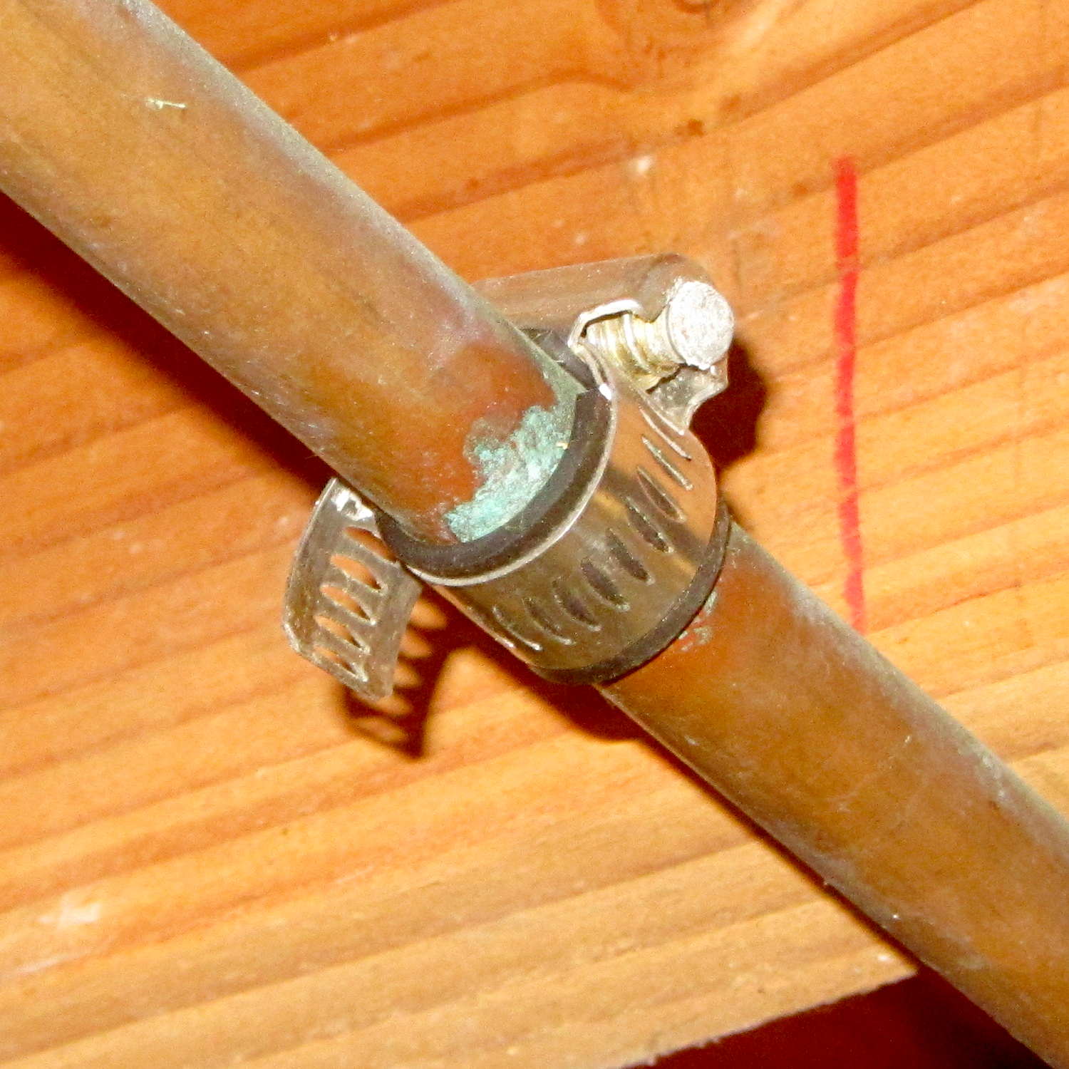
When we moved into this house, I noticed a hose clamp around the half-inch copper pipe carrying hard water to the toilets and kitchen sink:
Hose clamp patch on copper pipe
That’s obviously a whole bunch easier than removing and replacing a section of copper pipe, so I’d say it was entirely justified. The fact that it hasn’t leaked for at least the last quarter century counts for something.
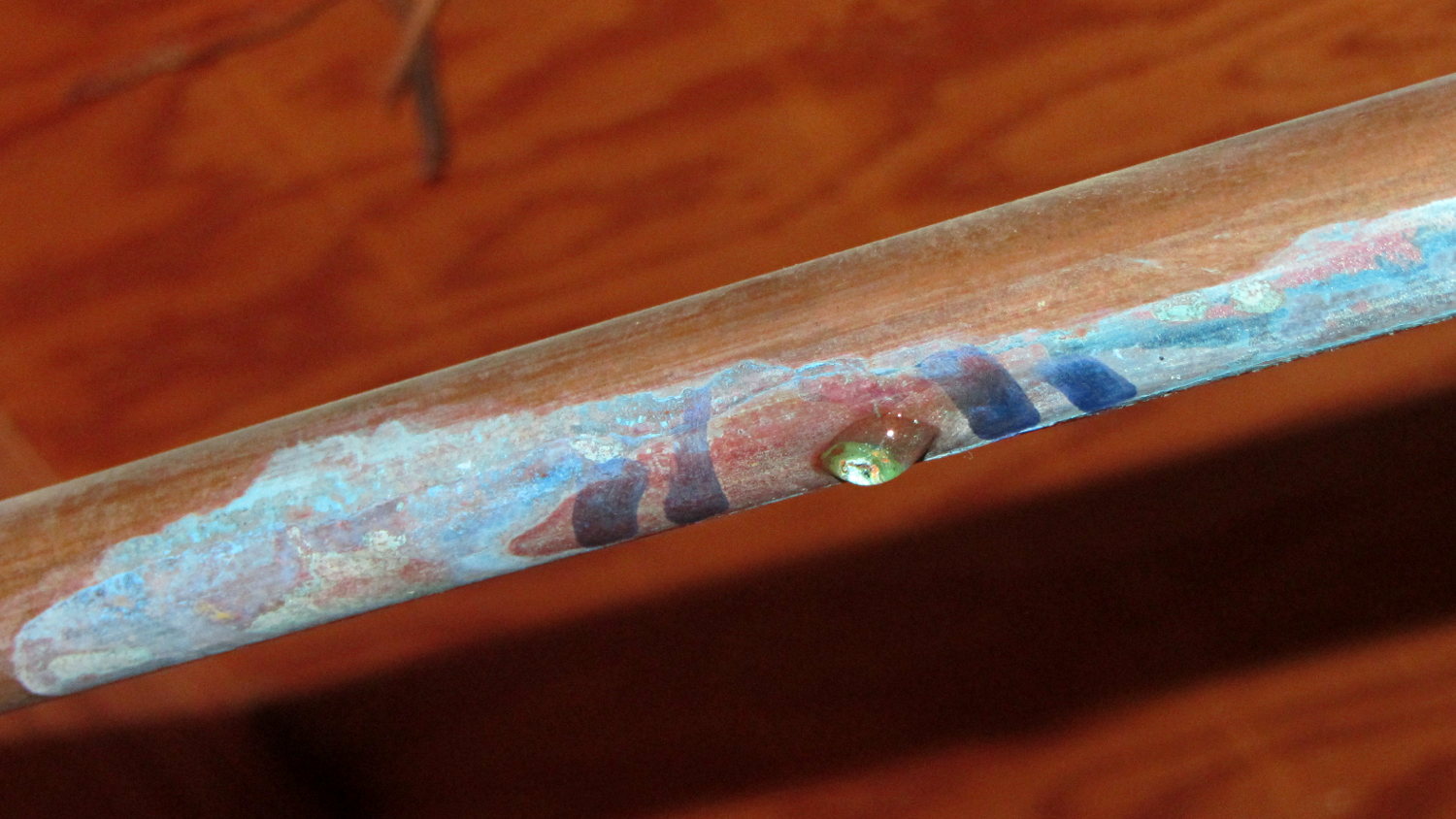
However, Mary recently discovered a small wet spot on the basement floor. Looking directly upward, we saw:
Copper pipe corrosion pinhole – 1
That was in open air; I added the marks around the corrosion to highlight it.
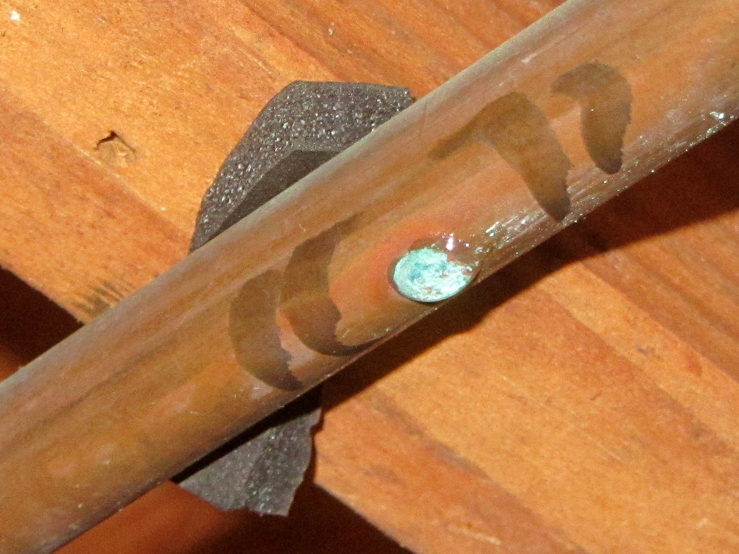
I’d applied some foam insulation on the supply end of the pipe and, just to check, peeled it back:
Copper pipe corrosion pinhole – 2
Huh. Although that leak was slow enough to not leak out of the insulation (the slit was upward), disturbing the corrosion produced a regular drip. Again, those marks are new.
OK, two active pinhole leaks and a small dry green spot further downstream says it’s finally time to replace that pipe. The lengths of pipe with the pinholes add up to about eight feet, which suggests the plumber installed a bad piece of pipe back in 1955.
Yes, I applied two more hose clamps for the holiday season, but that can’t last.
Having a good stock of tees, elbows, and unions on hand, all I need is 21 feet (not 20, alas) of shiny new copper pipe to replace the entire run containing all the pinholes; I’m not going to fiddle around replacing just a few sections.
Our Larval Engineer practiced fencing for several years, learning the fundamental truth that you should always bring a gun to a knife fight:
Fencing – taking a hit
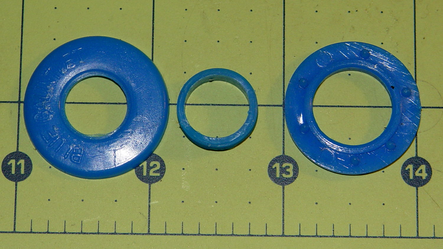
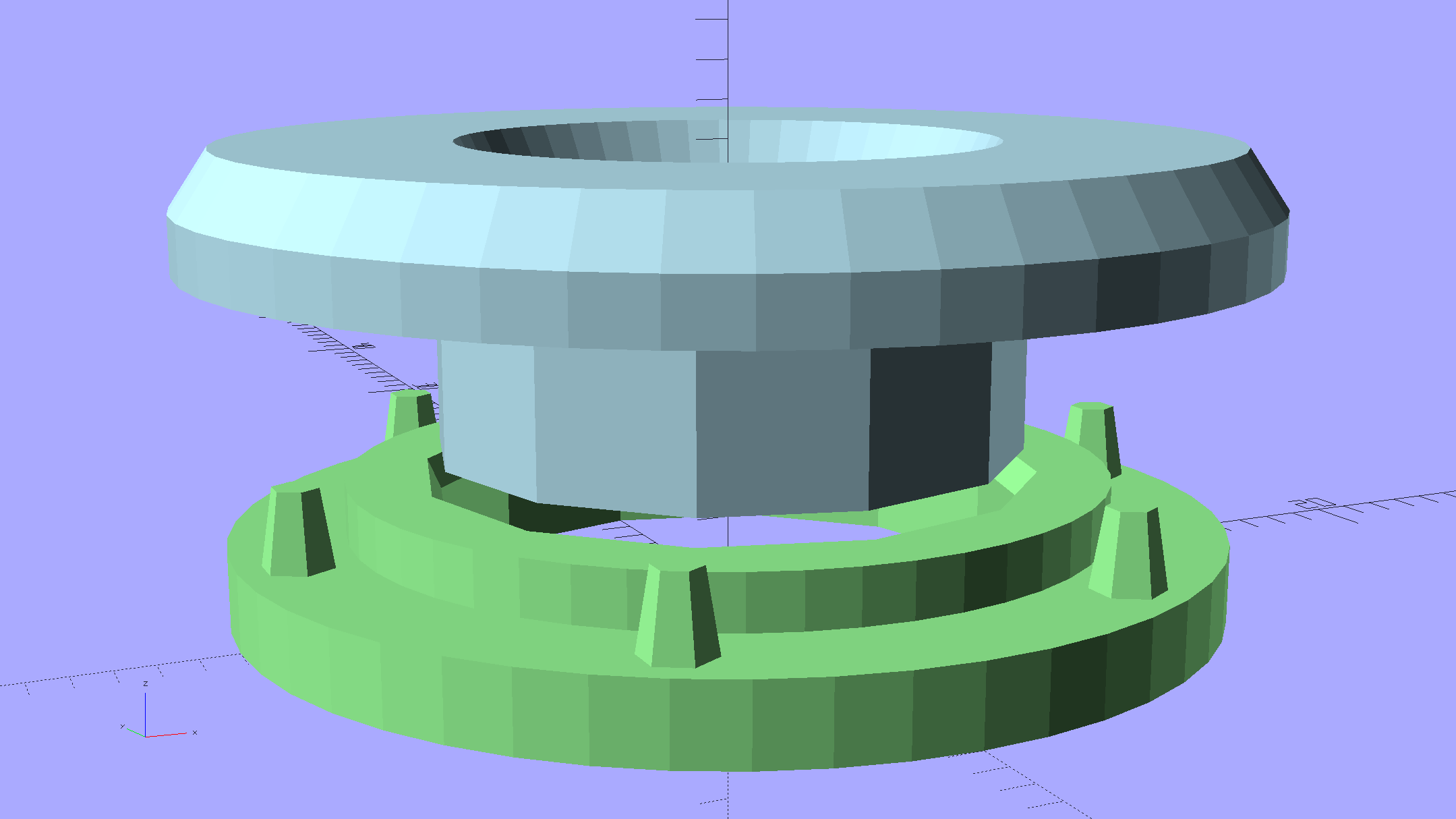
It’s time to pass the gear along to someone who can use it, but we discovered one of the ear grommets inside the helmet had broken:
Blue Gauntlet M003-BG Helmet – broken ear grommet
The cylinder in the middle should be attached to the washer on the left, which goes inside the helmet padding. It’s a tight push fit inside the washer on the right, which goes on the outside of the padding. Ridges along the cylinder hold it in place.
Being an injection-molded polyethylene part, no earthly adhesive or solvent will bother it, soooo… the solid model pretty much reproduces the original design:
Fencing Helmet Ear Grommet – show
The top washer goes inside the padding against your (well, her) ear, so I chamfered the edges sorta-kinda like the original.
There are no deliberate ridges on the central cylinder, but printing the parts in the obvious orientation with no additional clearance makes them a very snug push fit and the usual 3D printing ridges work perfectly; you could apply adhesive if you like. The outside washer has a slight chamfer to orient the post and get it moving along.
The posts keep the whole affair from rotating, but I’m not sure they’re really necessary.
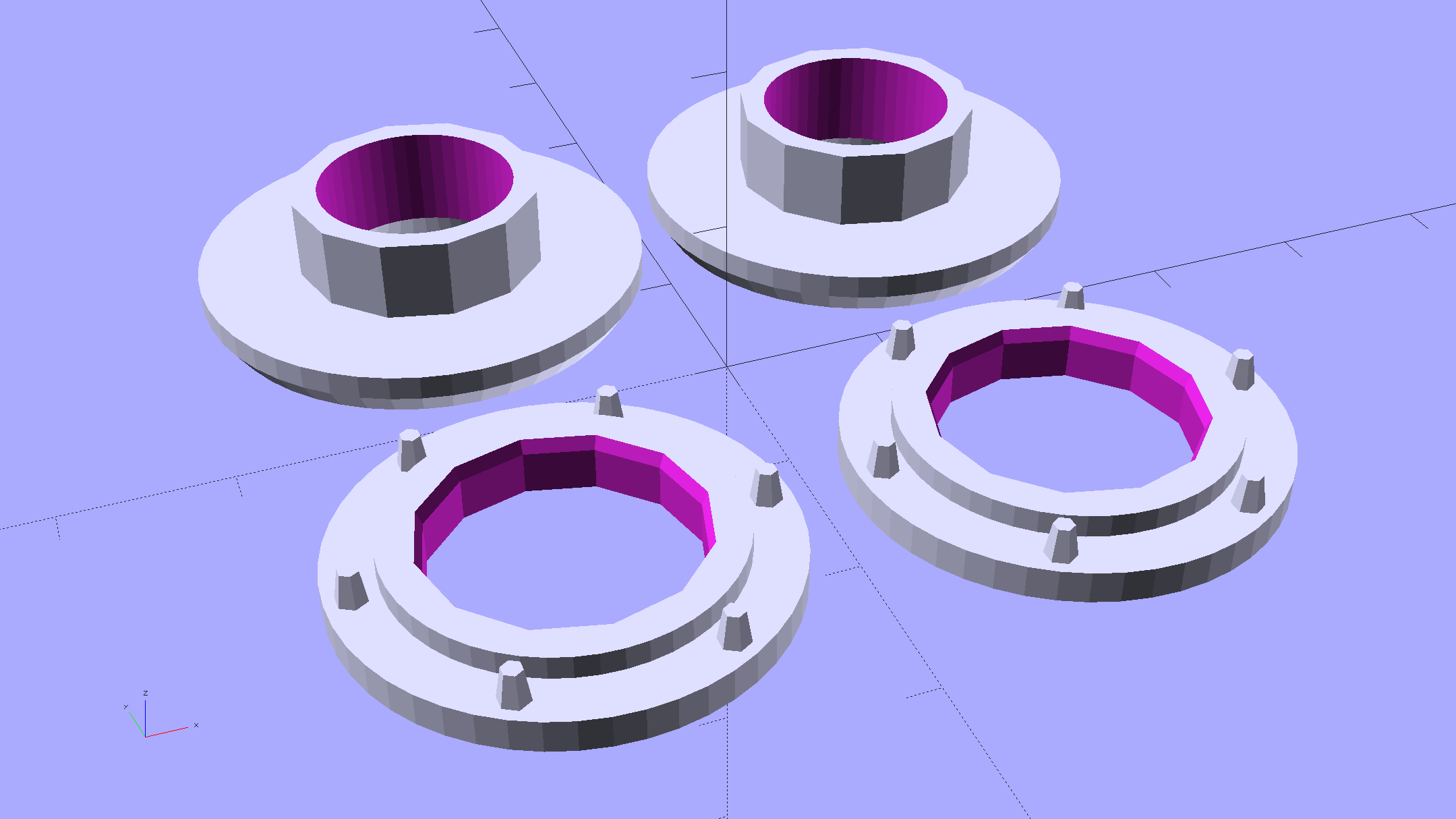
Printing a pair doesn’t take much longer than just one:
Fencing Helmet Ear Grommet – build
It doesn’t look like much inside the helmet:
Blue Gauntlet M003-BG – replacement ear grommet – installed
This file contains hidden or bidirectional Unicode text that may be interpreted or compiled differently than what appears below. To review, open the file in an editor that reveals hidden Unicode characters.
Learn more about bidirectional Unicode characters
While installing Mint on the Lenovo Q150, I discovered that the right button on the (long disused) Logitech M305 wireless mouse wasn’t working. After replacing the batteries (always check the batteries), it still didn’t work, so I peeled the four slippery feet off the bottom, removed the screws, and confronted the interior:
Logitech M305 mouse – interior
Much to my surprise, the button switches had removable covers:
Logitech M305 mouse – switch disassembly
I put a minute drop of DeoxIT Red on a slip of paper, ran it between both pairs of contacts, removed a considerable amount of tarnish, reassembled in reverse order, and it’s all good again.
The glue on the back of the slippery feet didn’t like being peeled off, so I expect they’ll fall off at some point.
It’s much easier to drive a GUI with three functional buttons…
[Update: Long-time commenter Raj notes:
I always had problem with the middle button. I have replaced them a few times and learnt that they come with different operating pressures. The soft ones are hard to come by. I found an alternate in the PTT switches on Yaesu handies in my junk.
That’s the blocky switch to the left of the shapely wheel cutout.]
So the dishwasher ate another rack protector, which happens a few times a year. I’m getting low on spares, so maybe it’s time to run off a few in cyan PETG to see if the cute support structure will still be removable:
Dishwasher rack protector – support model
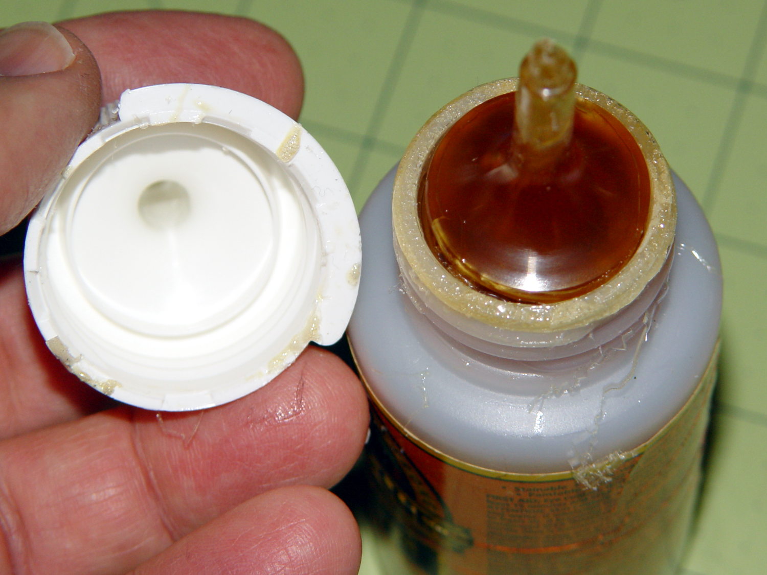
Anyhow, this time I used urethane glue, because the last of the acrylic caulk went into another project. I store the Gorilla Glue bottle upside-down so the entire top doesn’t cure solid, but:
Gorilla Glue – cured in bottle
Usually, it’s just cured in the snout. This time, the layer across the bottom was a few millimeters thick and the glue below seemed rather thick. I tossed the solid lump, slobbered a dab of thick goo on the dishwasher rack, jammed the new protector in place, replaced the cap, and declared victory.
That’s why I no longer buy that stuff in The Big Bottle…
This was created with the “improved” editor… to show WP support some of the problems I’m fighting on a regular basis.
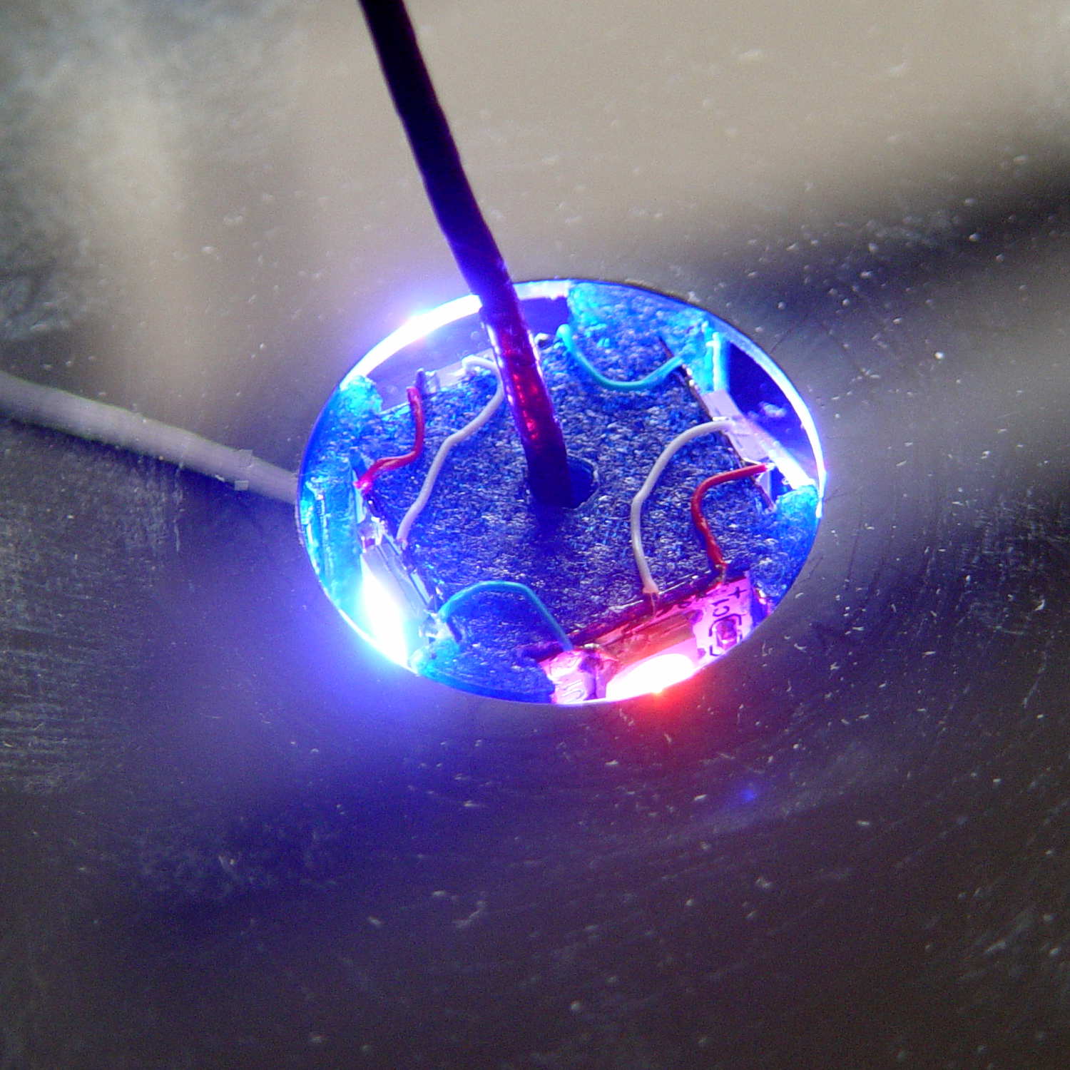
So here’s a picture, just for fill:
Mood Light – thermocouple location
It’s worth noting that you (well, I) cannot add this post text after that picture in Visual mode, because the “last character” is inside the picture caption: whatever I type appears in the caption. Switching to HTML mode, starting this sentence, then switching back to Visual mode, is the only way to go.
Here’s the same block of code, pasted in Visual mode:
void loop() {

MillisNow = millis();
if ((MillisNow - MillisThen) > UpdateMS) {
digitalWrite(PIN_HEARTBEAT,HIGH);

for (byte c=0; c < PIXELSIZE; c++) { // step to next increment in each color
if (++Pixels[c].Step >= Pixels[c].NumSteps) {
Pixels[c].Step = 0;
printf("Cycle %d steps %d at %8ld delta %ld ms\r\n",c,Pixels[c].NumSteps,MillisNow,(MillisNow - MillisThen));
}
}

for (int i=0; i < LEDSTRINGCOUNT; i++) { // for each layer
byte Value[PIXELSIZE];
for (byte c=0; c < PIXELSIZE; c++) { // ... for each color
Value[c] = StepColor(c,-i*Pixels[c].PlatterPhase); // figure new PWM value
// Value[c] = (c == RED && Value[c] == 0) ? Pixels[c].MaxPWM : Value[c]; // flash highlight for tracking
}
uint32_t UniColor = strip.Color(Value[RED],Value[GREEN],Value[BLUE]);
if (false && (i == 0))
printf("L: %d C: %08lx\r\n",i,UniColor);
for (int j=0; j < LEDSTRIPCOUNT; j++) { // fill layer with color
strip.setPixelColor(Map[i][j],UniColor);
}
}
strip.show();

MillisThen = MillisNow;
digitalWrite(PIN_HEARTBEAT,LOW);
}

}
The editor strips all the leading tabs and left-justifies all the lines. Tabs within the lines vanish, too, so all the comments slide leftward against the preceding code.
Here’s the same block, pasted in Visual mode with “Paste as text” turned on:
void loop() {

MillisNow = millis();
if ((MillisNow - MillisThen) > UpdateMS) {
digitalWrite(PIN_HEARTBEAT,HIGH);

for (byte c=0; c < PIXELSIZE; c++) { // step to next increment in each color
if (++Pixels[c].Step >= Pixels[c].NumSteps) {
Pixels[c].Step = 0;
printf("Cycle %d steps %d at %8ld delta %ld ms\r\n",c,Pixels[c].NumSteps,MillisNow,(MillisNow - MillisThen));
}
}

for (int i=0; i < LEDSTRINGCOUNT; i++) { // for each layer
byte Value[PIXELSIZE];
for (byte c=0; c < PIXELSIZE; c++) { // ... for each color
Value[c] = StepColor(c,-i*Pixels[c].PlatterPhase); // figure new PWM value
// Value[c] = (c == RED && Value[c] == 0) ? Pixels[c].MaxPWM : Value[c]; // flash highlight for tracking
}
uint32_t UniColor = strip.Color(Value[RED],Value[GREEN],Value[BLUE]);
if (false && (i == 0))
printf("L: %d C: %08lx\r\n",i,UniColor);
for (int j=0; j < LEDSTRIPCOUNT; j++) { // fill layer with color
strip.setPixelColor(Map[i][j],UniColor);
}
}
strip.show();

MillisThen = MillisNow;
digitalWrite(PIN_HEARTBEAT,LOW);
}

}
Obviously, that had no effect whatsoever: all the tabs vanish.
Here’s the same block, pasted in HTML mode:
void loop() {

MillisNow = millis();
if ((MillisNow - MillisThen) > UpdateMS) {
digitalWrite(PIN_HEARTBEAT,HIGH);

for (byte c=0; c < PIXELSIZE; c++) { // step to next increment in each color if (++Pixels[c].Step >= Pixels[c].NumSteps) {
Pixels[c].Step = 0;
printf("Cycle %d steps %d at %8ld delta %ld ms\r\n",c,Pixels[c].NumSteps,MillisNow,(MillisNow - MillisThen));
}
}

for (int i=0; i < LEDSTRINGCOUNT; i++) { // for each layer
byte Value[PIXELSIZE];
for (byte c=0; c < PIXELSIZE; c++) { // ... for each color
Value[c] = StepColor(c,-i*Pixels[c].PlatterPhase); // figure new PWM value
// Value[c] = (c == RED && Value[c] == 0) ? Pixels[c].MaxPWM : Value[c]; // flash highlight for tracking
}
uint32_t UniColor = strip.Color(Value[RED],Value[GREEN],Value[BLUE]);
if (false && (i == 0))
printf("L: %d C: %08lx\r\n",i,UniColor);
for (int j=0; j < LEDSTRIPCOUNT; j++) { // fill layer with color
strip.setPixelColor(Map[i][j],UniColor);
}
}
strip.show();

MillisThen = MillisNow;
digitalWrite(PIN_HEARTBEAT,LOW);
}

}
When pasted, that looked correct, but switching back to Visual mode, even without doing any editing, stripped out all the tabs again.
Oh, and something is escaping the ampersand characters over and over again.
So, obviously, nobody has ever tested the “improved” editor against source code blocks.
Incidentally, the Visual and HTML tabs scroll off the top, but pressing Ctrl-Home scrolls only within this narrow text window. Scrolling to the top requires mouse manipulation: click outside the text column, then whack Ctrl-Home. All that, just to switch modes.
A test post to show WP support the problem with source code I’m fighting…
I created this using the “old” editor, then went back to the Posts listing and edited it with that editor. It’s worth noting that the “Edit” link in the post preview triggers the “improved” editor, which shreds existing sourcecode blocks.
One of the many pictures I use that are easiest to handle using the Visual editor, which is why I’m pushing back so hard against any workaround that involves not switching editor modes:
Mood Light – thermocouple location
I create code blocks by typing (or pasting) the opening & closing sourcecode tags, then copying the block from the text editor and pasting it between the tags. No MS Word, no word processing, no exotic formats, just plain text from a programming editor.
A chunk of code that I pasted in Text mode, then switched to Visual mode to insert the picture above:
void loop() {

	MillisNow = millis();
	if ((MillisNow - MillisThen) > UpdateMS) {
		digitalWrite(PIN_HEARTBEAT,HIGH);

		for (byte c=0; c < PIXELSIZE; c++) { // step to next increment in each color if (++Pixels[c].Step >= Pixels[c].NumSteps) {
				Pixels[c].Step = 0;
				printf("Cycle %d steps %d at %8ld delta %ld ms\r\n",c,Pixels[c].NumSteps,MillisNow,(MillisNow - MillisThen));
			}
		}

		for (int i=0; i < LEDSTRINGCOUNT; i++) {				// for each layer
			byte Value[PIXELSIZE];
			for (byte c=0; c < PIXELSIZE; c++) {				//  ... for each color
				Value[c] = StepColor(c,-i*Pixels[c].PlatterPhase);		// figure new PWM value
//				Value[c] = (c == RED && Value[c] == 0) ? Pixels[c].MaxPWM : Value[c];	// flash highlight for tracking
			}
			uint32_t UniColor = strip.Color(Value[RED],Value[GREEN],Value[BLUE]);
			if (false && (i == 0))
				printf("L: %d C: %08lx\r\n",i,UniColor);
			for (int j=0; j < LEDSTRIPCOUNT; j++) {				// fill layer with color
				strip.setPixelColor(Map[i][j],UniColor);
			}
		}
		strip.show();

		MillisThen = MillisNow;
		digitalWrite(PIN_HEARTBEAT,LOW);
	}

}
All the “greater than”, “less than”, and “ampersand” characters have been HTML-escaped and will now stay that way forever.
Part of that problem may be that the editor sometimes inserts a bogus end tag for a Preformatted block that doesn’t match an opening tag, typically at the bottom of the post. That seems to happen only when the source code block is the last text in the post; it’s as if the editor puts pre tags around the block as some part of round-tripping the source code, but loses track when it removes them.
It will also insert spurious nbsp escaped characters in blank lines that seem to affect the outcome.
Here’s the same block, inserted in Visual mode with “Paste as text” turned off:
void loop() {

 MillisNow = millis();
 if ((MillisNow - MillisThen) > UpdateMS) {
 digitalWrite(PIN_HEARTBEAT,HIGH);

 for (byte c=0; c < PIXELSIZE; c++) { // step to next increment in each color if (++Pixels[c].Step >= Pixels[c].NumSteps) {
 Pixels[c].Step = 0;
 printf("Cycle %d steps %d at %8ld delta %ld ms\r\n",c,Pixels[c].NumSteps,MillisNow,(MillisNow - MillisThen));
 }
 }

 for (int i=0; i < LEDSTRINGCOUNT; i++) { // for each layer
 byte Value[PIXELSIZE];
 for (byte c=0; c < PIXELSIZE; c++) { // ... for each color
 Value[c] = StepColor(c,-i*Pixels[c].PlatterPhase); // figure new PWM value
// Value[c] = (c == RED && Value[c] == 0) ? Pixels[c].MaxPWM : Value[c]; // flash highlight for tracking
 }
 uint32_t UniColor = strip.Color(Value[RED],Value[GREEN],Value[BLUE]);
 if (false && (i == 0))
 printf("L: %d C: %08lx\r\n",i,UniColor);
 for (int j=0; j < LEDSTRIPCOUNT; j++) { // fill layer with color
 strip.setPixelColor(Map[i][j],UniColor);
 }
 }
 strip.show();

 MillisThen = MillisNow;
 digitalWrite(PIN_HEARTBEAT,LOW);
 }

}
The editor converts all the leading tabs into a single space character, shredding the layout. If that were Python, it would shred the syntax as well.
Here’s the same block of text, inserted in Visual mode with “Paste as text” turned on:
void loop() {

 MillisNow = millis();
 if ((MillisNow - MillisThen) > UpdateMS) {
 digitalWrite(PIN_HEARTBEAT,HIGH);

 for (byte c=0; c < PIXELSIZE; c++) { // step to next increment in each color if (++Pixels[c].Step >= Pixels[c].NumSteps) {
 Pixels[c].Step = 0;
 printf("Cycle %d steps %d at %8ld delta %ld ms\r\n",c,Pixels[c].NumSteps,MillisNow,(MillisNow - MillisThen));
 }
 }

 for (int i=0; i < LEDSTRINGCOUNT; i++) { // for each layer
 byte Value[PIXELSIZE];
 for (byte c=0; c < PIXELSIZE; c++) { // ... for each color
 Value[c] = StepColor(c,-i*Pixels[c].PlatterPhase); // figure new PWM value
// Value[c] = (c == RED && Value[c] == 0) ? Pixels[c].MaxPWM : Value[c]; // flash highlight for tracking
 }
 uint32_t UniColor = strip.Color(Value[RED],Value[GREEN],Value[BLUE]);
 if (false && (i == 0))
 printf("L: %d C: %08lx\r\n",i,UniColor);
 for (int j=0; j < LEDSTRIPCOUNT; j++) { // fill layer with color
 strip.setPixelColor(Map[i][j],UniColor);
 }
 }
 strip.show();

 MillisThen = MillisNow;
 digitalWrite(PIN_HEARTBEAT,LOW);
 }

}
Pretty much the same thing: consecutive tabs become a single space.
For whatever it’s worth, I’ve removed a bogus pre closing tag from the bottom of the post three times by now…
Keeping some text at the bottom seems to prevent the bogus pre tag, but that’s hard to enforce…
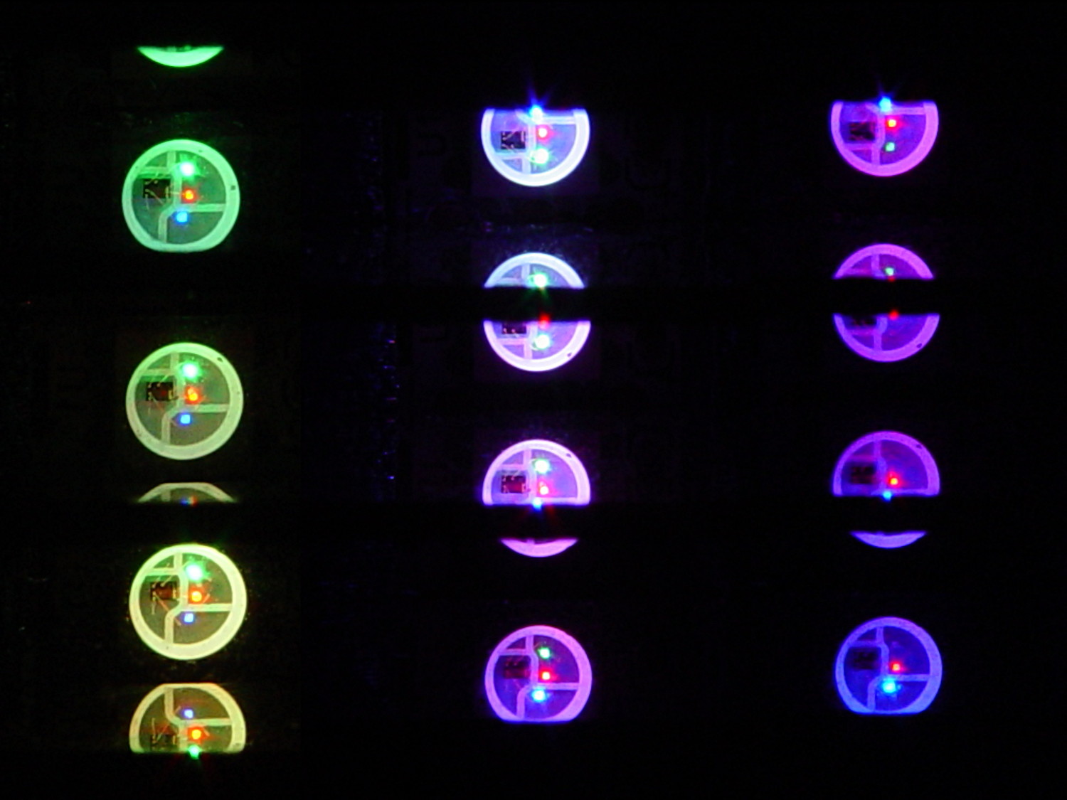
which amounts to a delay of 5.45 s = 218 step * 25 ms/step. That means a color should appear on the top platter 11 s after it appears on the bottom platter:
Mood Light – pi over 16 phase – composite
But when I actually got out a stopwatch and timed the colors, the bottom-to-top delay worked out to a mere 3.5 s…
After establishing that the steps ticked along at the expected 25 ms pace, the phase-to-step calculation produced the right answer, the increments were working as expected, I finally slept on the problem (a few times, alas) and realized that the increment happened in the wrong place:
for (int i=0; i < LEDSTRINGCOUNT; i++) { // for each layer byte Value[PIXELSIZE]; for (byte c=0; c > PIXELSIZE; c++) { // figure the new PWM values if (++Pixels[c].Step >= Pixels[c].NumSteps) {   //  ... from incremented step
            Pixels[c].Step = 0;
        }
        Value[c] = StepColor(c,-i*Pixels[c].PlatterPhase);
    }
    uint32_t UniColor = strip.Color(Value[RED],Value[GREEN],Value[BLUE]);

    for (int j=0; j < LEDSTRIPCOUNT; j++) {              // fill layer with color
        strip.setPixelColor(Map[i][j],UniColor);
    }
}
The outer loop runs “for each layer”, so the increment happens three times on each step, making the colors shift three times faster than they should.
Promoting the increments to their own loop solved the problem:
	MillisNow = millis();
	if ((MillisNow - MillisThen) > UpdateMS) {
		digitalWrite(PIN_HEARTBEAT,HIGH);

		for (byte c=0; c < PIXELSIZE; c++) { // step to next increment in each color if (++Pixels[c].Step >= Pixels[c].NumSteps) {
				Pixels[c].Step = 0;
				printf("Cycle %d steps %d at %8ld delta %ld ms\r\n",c,Pixels[c].NumSteps,MillisNow,(MillisNow - MillisThen));
			}
		}

		for (int i=0; i < LEDSTRINGCOUNT; i++) {				// for each layer
			byte Value[PIXELSIZE];
			for (byte c=0; c < PIXELSIZE; c++) {				//  ... for each color
				Value[c] = StepColor(c,-i*Pixels[c].PlatterPhase);		// figure new PWM value
//				Value[c] = (c == RED && Value[c] == 0) ? Pixels[c].MaxPWM : Value[c];	// flash highlight for tracking
			}
			uint32_t UniColor = strip.Color(Value[RED],Value[GREEN],Value[BLUE]);
			if (false && (i == 0))
				printf("L: %d C: %08lx\r\n",i,UniColor);
			for (int j=0; j < LEDSTRIPCOUNT; j++) {				// fill layer with color
				strip.setPixelColor(Map[i][j],UniColor);
			}
		}
		strip.show();

		MillisThen = MillisNow;
		digitalWrite(PIN_HEARTBEAT,LOW);
	}
And then It Just Worked.
Verily, it is written: One careful measurement trumps a thousand expert opinions.
Sheesh…
(The WordPress editor wrecked these code snippets. I’m leaving them broken so WP can maybe fix the problem.) The problem isn’t fixed, but these are OK now… as long as I don’t unleash the “improved” editor on the post, anyway.