Ed Nisley's Blog: Shop notes, electronics, firmware, machinery, 3D printing, laser cuttery, and curiosities. Contents: 100% human thinking, 0% AI slop.
The ER-16 and ER-32 collet chucks use an M12×1.75 bolt to snug their MT3 tapers in the Mini-Lathe spindle. As nearly as I could figure, I needed a 190 mm bolt to get enough thread engagement, but the nearest available sizes were either too short or too long.
Fortunately, making round things is what a lathe is all about:
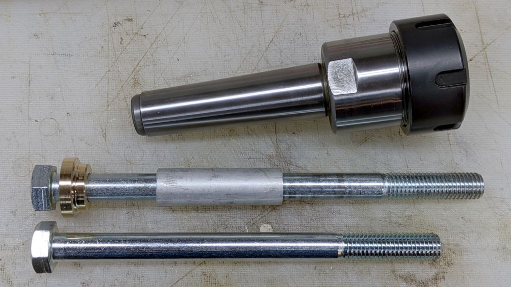
MT3 drawbar – assembled
The aluminum bellyband adds 30 mm to the length and aligns the bolt sections, with the threaded section from a long 5/16-18 bolt inside holding the metric bolt together:
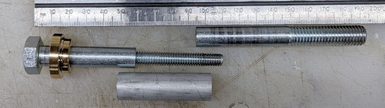
MT3 drawbar – parts
Although I got it right on the first try (!), the bellyband lets me fine-tune the length as needed.
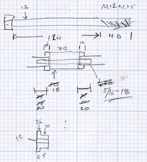
The original dimension doodle and some in-flight updates:
ER Collets – MT3 drawbar bolt – dimension doodles
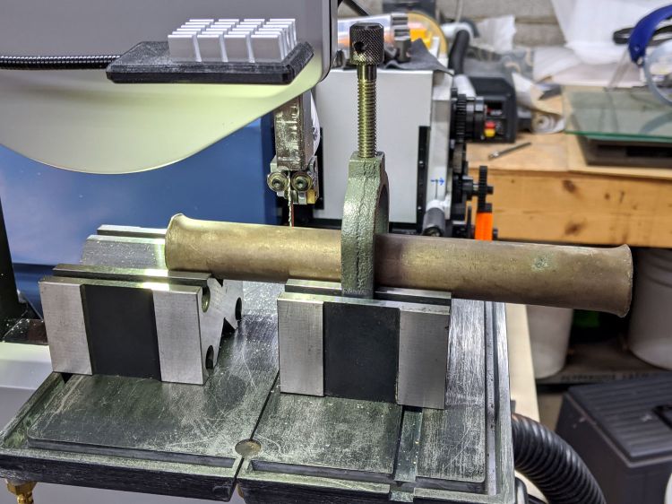
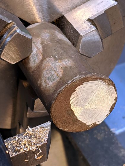
The fancy brass / bronze washer comes from a battered rod with mushroomed ends. A pair of V-blocks let me cut a chunk off one end with negligible drama:
Bronze Bar Stock – support fixture
It’s clamped firmly to the right block and a few licks with a file knocked off enough of the mushroom on the left end to put it flat(-ish) into the V; the near side of the right block is barely raised off the surface.
Face off the mushroom to get a flat spot for a center drill:
MT3 drawbar – battered bronze rod
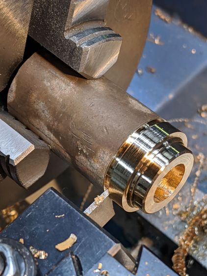
Some peaceful turning & boring produces a pretty washer:
MT3 drawbar – washer cutoff
The bore needed a bit of relief to seat the bolt head squarely on the outer surface:
MT3 drawbar – spindle washer
And then It Just Fit™:
MT3 drawbar – installed
Loctite on the inner bolt threads should keep everything together.
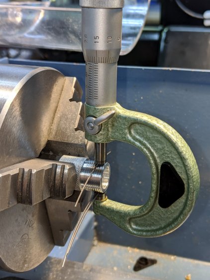
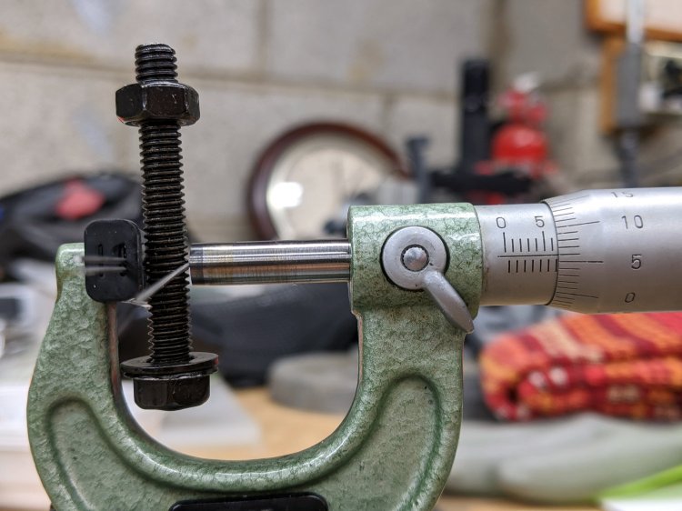
Those are three lengths of music wire, slightly bent from their storage roll, held in place with a precision clamp metric micrometer. Given the crudity of the setup, the uncalibrated wire diameter, and my lack of thread-fu, the results came out both close and unconvincing.
The 185 mil “wires” (they’re all allegedly ground rod) will let me cut threads matching things like a Jesus nut; they’re suited for 3 TPI / 8 mm pitch screws. Mostly, wires from the front row will be all I ever need.
The black doodad (the set includes half a dozen for all the wire sizes) fits over the micrometer anvil and holds two wires betwixt anvil and screw, leaving me to manipulate the screw, the third wire, and the micrometer with my remaining hands. Hence the vise holding the micrometer, which is known to be Very Bad Practice.
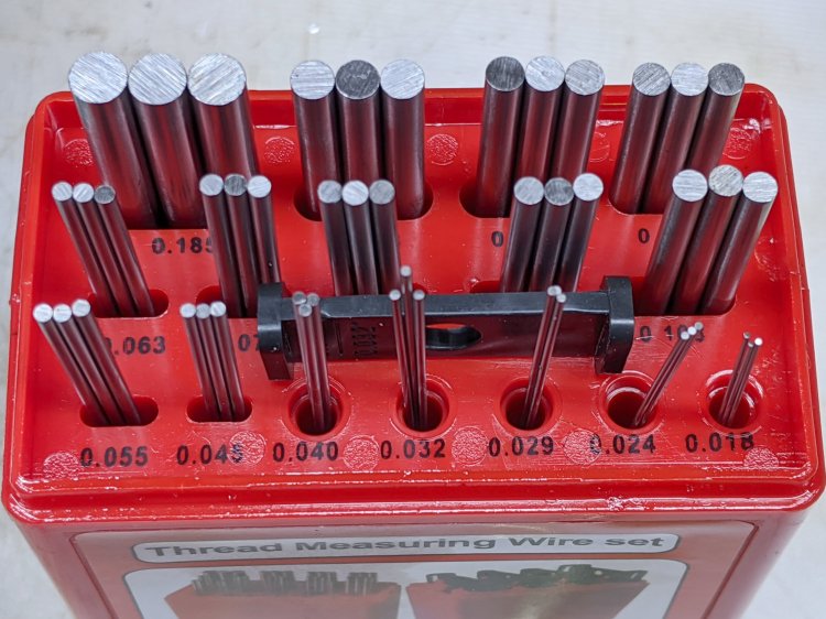
From the side:
Thread Measuring Wires – overview
All of the smaller wires measure 0.5 mil too thin, which is likely due to my lack of calibrated measurement equipment:
Thread Measuring Wires – scant 24 mil
The few thread pitch diameters I measured also came out slightly too small, again likely due to calibration and screw tolerances.
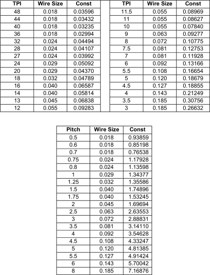
To forestall link rot, a slightly rearranged version of their tables of wire constants:
Thread Wire Measurement Constants
The lower table has metric thread pitches with the wire sizes in inches.
You measure the distance over the recommended wire (in inches or millimeters, as appropriate), subtract the constant, and get the pitch diameter in the same units. Conversely, add the constant to the desired pitch diameter to get the target over-wire distance, carefully cut the thread until it measures a bit less than that, back up sixty seconds, and cut it spot on.
Verily, it is written: there is no UnDo key (⎌) in machine shop work.
Chuck up a length of 5/8 inch aluminum tube, clean up the end, and poke a thread runout slot into it:
Floor Lamp – tube fitting – thread runout
Turn the soon-to-be-thread OD to 14.7 mm, well under the minimum 14.794 mm major thread diameter. I figure it’s better to match the existing not-quite-standard tube threads than to get all fussy about tolerances:
Floor Lamp – tube fitting – thread OD
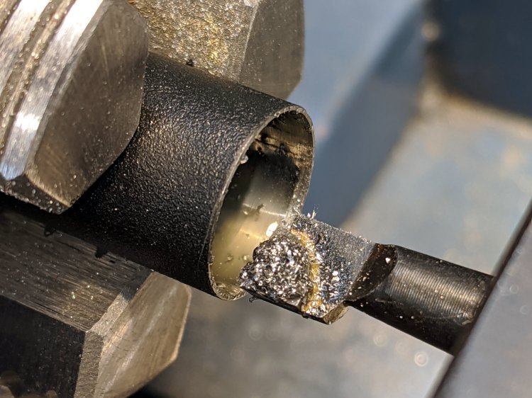
Drill out the tube to 27/64 inch = 0.422 inch = 10.7 mm, a bit larger than the OEM fittings, to easily pass the JST-SM connector I added so I could take the lamp apart:
Floor Lamp – tube fitting – drilling bore
Yeah, you’re not supposed to let the swarf build up like that, but it’s hard to stop when you’re getting good chip.
The compound is at 90° to the cross slide, because the DRO housing doesn’t let the compound swivel to the proper angle for thread cutting. I’m just ramming the threader straight into the tube, taking sissy cuts, and hoping for the best.
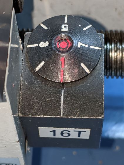
Kiss the OD with the cutter, set the cross slide DRO to zero, position the cutter just off the end of the tube, close the split nuts around the leadscrew, engage the threading dial at a conspicuous mark:
Mini-Lathe Threading Dial – aligned
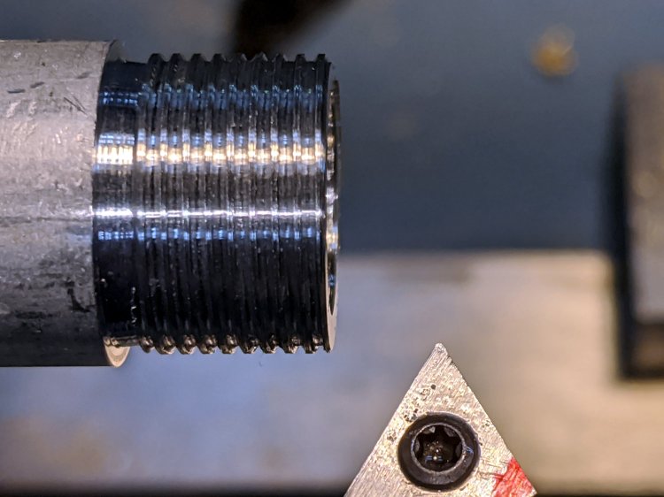
The first real pass looked good:
Floor Lamp – tube fitting – first thread pass
The runout slot is 1/16 inch = 1.6 mm wide and I’m running the lathe dead slow, so there’s plenty of time to punch the STOP button as the cutter enters the slot and let the spindle coast down. Flip the switch to REVERSE, crank the cross slide out a turn (1 mm with 0.3 mm of crank backlash), run the cutter back to the starting point, crank the cross slide in, and iterate until the fitting screws into one of the OEM lamp tubes:
Floor Lamp – tube fitting – final thread
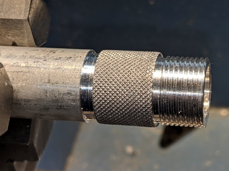
The 5/8 inch tube is just a smidge too small for the copper fitting, so knurl the fitting to enlarge the OD slightly more than a smidge:
Floor Lamp – tube fitting – knurled
Break the knurl edges, part off the fitting, clean up the new end, and do it all over again:
Floor Lamp – tube fitting – threaded adapters
The knurls got filed down to an exact slip fit in the copper elbow and will eventually be epoxied in place.
The cut-off tube on the lamp head also needs internal threads, so bore out the interior to flatten the weld seam:
Floor Lamp – tube fitting – cleaning tube bore
No pix of the threading, but you have the general idea; the tube wall is a scant 0.6 mm thick, so this isn’t the place for full-spec threads. I stopped when the OEM tube screwed in place.
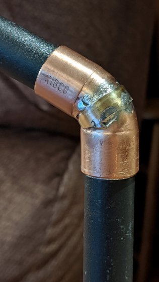
Apart from the hideous solder job, it came together pretty well:
Floor Lamp – tube fitting – unpainted
It’s much more stable than Kapton-wrapped tubes jammed into a bare copper fitting, although that’s not saying much.
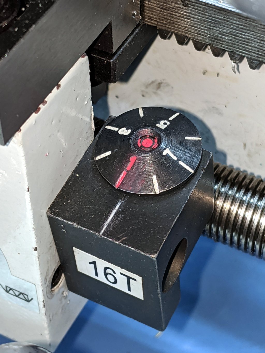
As received, the mini-lathe’s threading dial was misaligned by about 1/4 division, which is nearly halfway to the next engagement point midway between the divisions:
Mini-Lathe Threading Dial – as received – colorized
I added the red lacquer crayon while contemplating what to do, because I thought the dial was swaged onto the shaft. It turns out to be threaded, so I marked where the dial should be, grabbed the shaft in the (soft-jawed) bench vise, and twisted the dial with a Vise-Grip until it lined up:
Mini-Lathe Threading Dial – aligned
Well, it’s closer than it was, OK?
There’s about that much slop on either side of the index line coming from the loose gear engaging the leadscrew, so that’s as good as it gets.
Running my assortment of custom 3D printed change gears through the LittleMachineShop calculator and copying the results into a spreadsheet for E-Z formatting produces a useful table:
Although OpenSCAD’s MCAD library includes a gear generator, I don’t profess to understand the relations between reality and its myriad parameters, plus I vaguely recall it has a peculiar definition for Diametral Pitch (or some such). Rather than fiddle with all that, I start with an SVG outline from Inkscape’s Gears extension and go all 3D on it.
So, the “gear blank” looks like this after extruding the SVG:
Mini-lathe change gear – 42 tooth – SVG import
Producing this is a lot easier in OpenSCAD than in real life:
Mini-lathe change gear – 42 tooth – solid model
OpenSCAD centers the blank’s bounding box at XY=0, which won’t be exactly on the bore centerline for gears with an odd number of teeth. One tooth sits at 0° and two teeth bracket 180°, so the bounding box will be a little short on one side
A reference for gear nomenclature & calculations will come in handy.
For a 21 tooth module 1 gear, which should be pretty close to the worst case in terms of offset:
Pitch dia = d = 21 × 1 = 21 mm
Tip dia = da = d + 2m = 23 mm
Tip radius = da/2 = 11.5 mm
Tooth-to-tooth angle = 360/21 = 17.143°
Radius to tangent across adjacent teeth = 11.5 × cos 17.143°/2 = 11.372 mm
An actual metal 21 tooth gear measures 22.87 mm across a diameter, dead on what those numbers predict: 11.5 + 11.372 = 22.872 mm.
So the bounding box will be 11.5 mm toward the tooth at 0° and 11.372 mm toward the gap at 180°. The offset will be half that, with the tooth at 0° sitting 0.063 mm too close to the origin. Gears with more teeth will have smaller errors.
Given that we’re dealing with a gear “machined” from plastic goo, that’s definitely close enough:
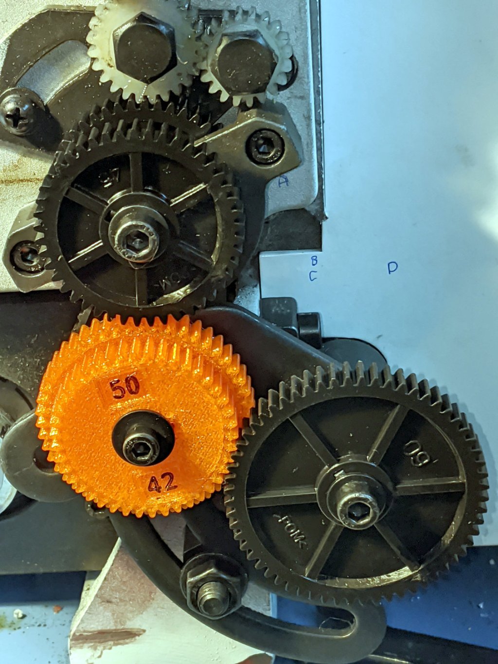
Mini-Lathe change gears – 1 mm – 45-50-45-60
That’s an earlier version with the debossed legend.
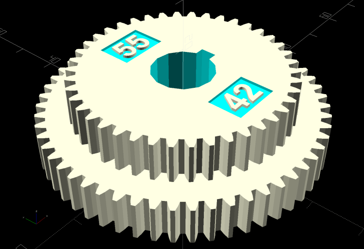
The code can also generate stacked gears for the BC shaft in the middle:
Mini-lathe change gear – 42-55 tooth stacked – solid model
In principle, the key locking the gears together isn’t needed and the bore could fit the inner shaft, rather than the keyed bushing, but then you’d (well, I’d) be at risk of losing the bushing + key in one easy operation.
This file contains hidden or bidirectional Unicode text that may be interpreted or compiled differently than what appears below. To review, open the file in an editor that reveals hidden Unicode characters.
Learn more about bidirectional Unicode characters