Ed Nisley's Blog: Shop notes, electronics, firmware, machinery, 3D printing, laser cuttery, and curiosities. Contents: 100% human thinking, 0% AI slop.
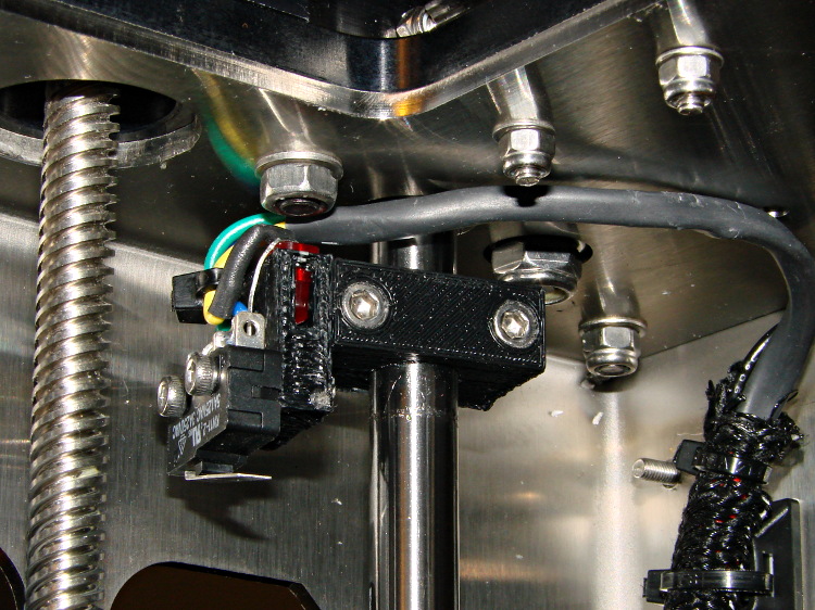
The best orientation for the Z-minimum switch seems to be slightly angled back:
M2 – Z min limit switch
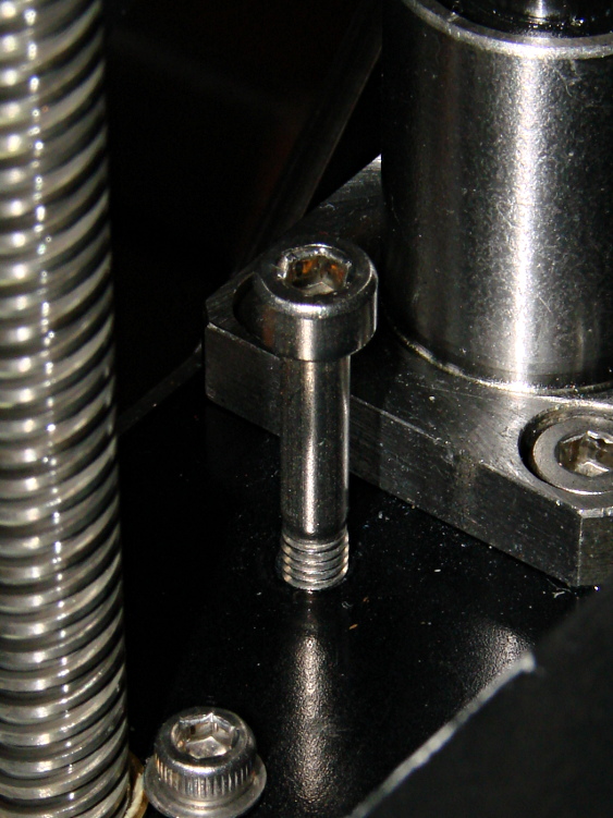
I used an M4x0.7 socket head cap screw for the height adjustment, with a Nylock nut below the stage:
M2 – Z min limit screw
The assembly instructions show a hex head screw, but the item numbers don’t match the BOM listings. The SHCS lets me hold it firmly in position with the ball-end driver provided in the M2 tool kit while adjusting it:
1/4 turn (the handle is square-ish) = 0.7/4 = 0.175 mm
1/6 turn (the shaft is hex) = 0.12 mm
1/12 turn (you can do it!) = 0.06mm
less than that is probably fooling yourself.
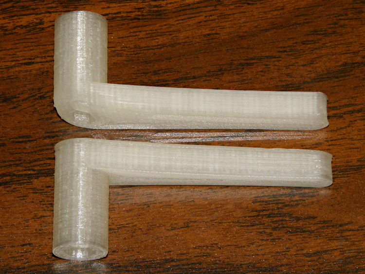
I printed a pair of tomlombardi’s 7 mm wrenches, which work well for adjusting the Nylock nut underneath the Z axis stage:
M2 – 7 mm wrenches
The left end of the top wrench didn’t adhere to the glass plate, but the business end of the wrench came out OK.
I adjusted the screw to trip the switch with the nozzle 1.0 mm above the platform, then feed that offset in using a G92 Z1.0 instruction in my customized Start G-Code.
However, the most accurate way to set the switch height involves measuring the as-printed thickness of the skirt extrusion around the object. The average value should be 0.25 mm (for my current slic3r settings, anyhow) and all sides should be equally thick: adjust the screw to change the average and adjust the platform screws to remove any tilt. You’ll quickly accumulate a pile of skirt threads, but they make good tchotchkes when you give a presentation on your new toy:
M2 skirt extrusions
You could fiddle with the G92 value to make the average thickness come out right, but I favor making the machine as accurate as possible, so that the software begins from a known-good mechanical setting.
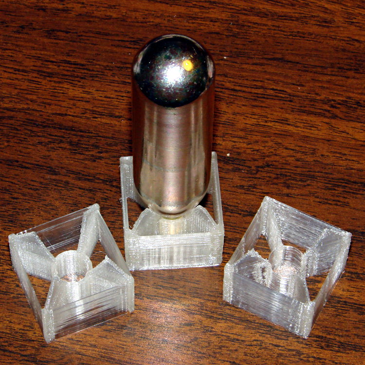
I redesigned those fins to fit 16 gram threaded CO2 cartridges in PLA on the M2:
M2 CO2 capsule fins
The original intent was to have both the square box and the internal X struts be exactly two threads wide, but the two fins on the sides show slic3r had some trouble doing that. I finally made them wide enough for a little fill, which produced the rather chunky version attached to the capsule.
A closer look while printing shows the fin width:
M2 – CO2 Capsule Fins – on platform
It was actually a present to go along with a box of the capsules, so I printed just one in a bit of a hurry. He probably couldn’t get them back across the border, but it’s the thought that counts, right?
While changing to black filament, I measured the force required to pull the (natural PLA) filament through the translucent guide tube arching over the M2’s chassis from the spool to the extruder:
Makergear M2 3D Printer with cardboard on build platform
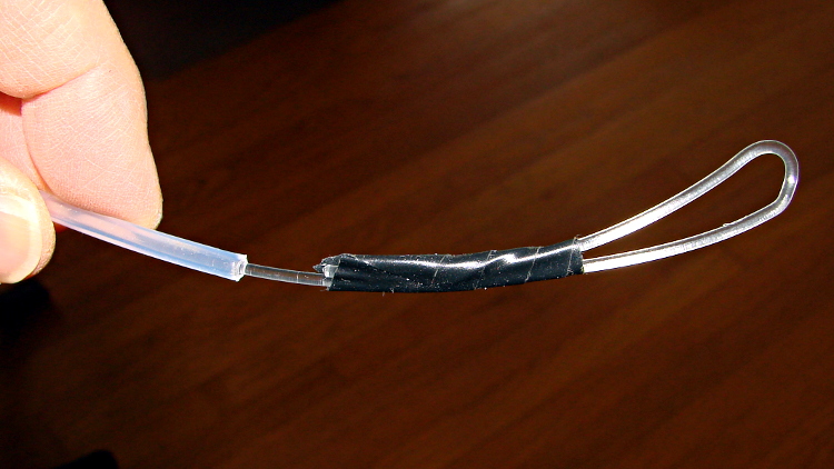
A strike-anywhere kitchen match (bet you can’t buy those any more!) provided more than enough heat to bend the end of the filament into a loop suitable for the pull scale:
M2 – Filament loop for pull test
The results:
Tube reasonably straight: 0.5 lb = 2.2 N
Tube arched to middle of X axis: 1 lb = 4.5 N
Tube sharply bent to X axis nearest spool: 1.5 lb = 6.7 N
The force increases slightly while tugging filament off the spool, as the spool does not rotate freely on the printed arm jutting out from the frame, but those numbers are in the right ballpark.
The effective diameter of the extruder drive gear is about 11.5 mm, so overcoming the tube friction requires somewhere between 10 and 40 mN·m of torque. That’s applied at the one point in the whole system most likely to show the result of uneven loading, because it directly affects the pressure of the molten plastic behind the nozzle.
That’s considerable motivation to get rid of the filament guide tube…
set port /dev/ttyACM0
set baudrate 115200
set build_dimensions 200x240x195-100-120+0
set temperature_abs 200
set last_bed_temperature 70.0
set last_temperature 155.0
set xy_feedrate 30000
set z_feedrate 2500
set e_feedrate 300
set last_file_path /mnt/bulkdata/Project Files/Thing-O-Matic/Calibration
set temperature_pla 165
set preview_grid_step1 10
set preview_grid_step2 20.0
set preview_extrusion_width 0.4
set bedtemp_pla 70
Line 3 sizes the preview and offsets the XY=0 origin to the center of the plot.
The 200 mm X axis dimension is slightly larger than the actual 195 mm buildable area on the platform, but if the object gets that close to the maximum size, this isn’t the place to discover it.
The 240 mm Y axis dimension is slightly shorter than the actual 250 mm buildable area and slightly larger than the distance between the snouts of the bulldog clips holding the glass plate to the heater. In this case, the object can slightly exceed the preview size if it fits between the clips.
Lines 12 and 13 produce a relatively coarse grid that’s both meaningful and easy on the eyes, with the XY dimensions in Line 3 producing a major grid line crossing at the origin where it should be:
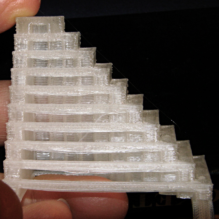
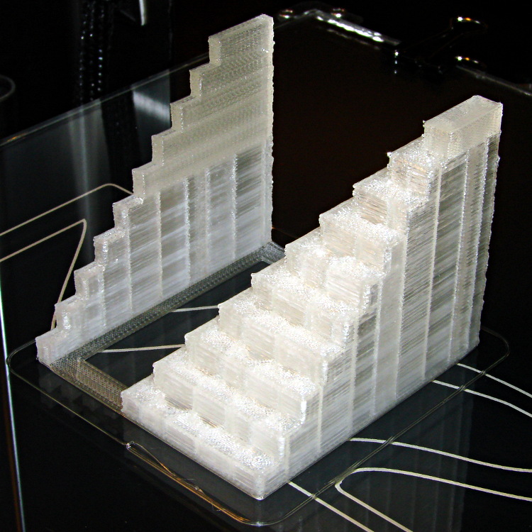
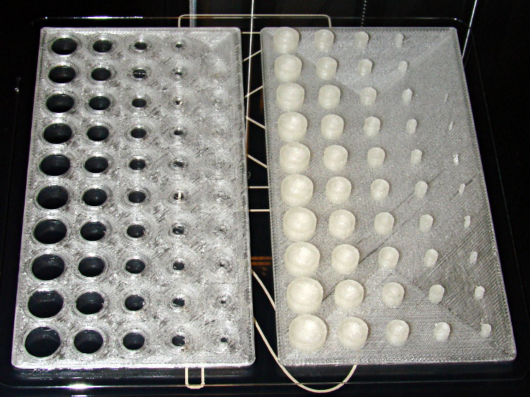
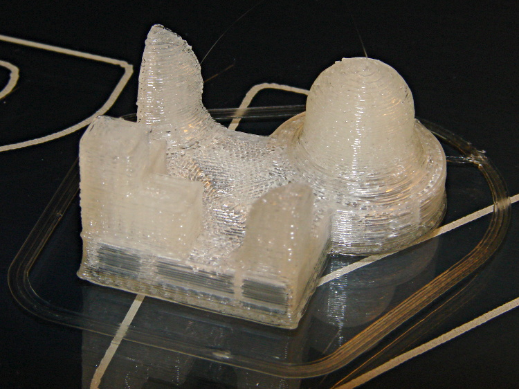
Despite the profusion of surface-finish and print quality test objects, I really care about the dimensions of a 3D printed object, because I tend to build widgets rather than art objects. These two objects, from walter’s Hole and Column Test Print, produce calibrated holes and columns from 0.20 mm to 10.00 mm in diameter, incrementing by 0.20 mm, that should slip neatly together:
M2 – walter hole-column test
Of course, they didn’t, but they came surprisingly close for a first attempt.
The 0.20 and 0.40 posts simply aren’t there, because they’re too small to print with a 0.35 mm diameter nozzle. The 0.60 through 1.40 mm posts were present, albeit fugly, and posts larger than that looked increasingly better.
Although all the holes were present, in the sense that you could see a disturbance in the top and bottom infill pattern, the first visibly open hole appeared at the 0.80 mm spot… and it was immeasurably small. Some holes had misplaced perimeter strands stretching across the openings, which is probably due to excessive speed from my fiddling around with the numbers.
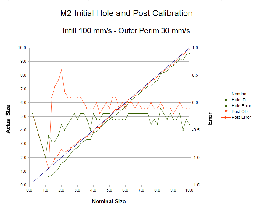
Measuring them with a digital caliper, with no effort at finding the best orientation, then slapping the data into a Libreoffice spreadsheet, produces an interesting graph:
M2 – Initial Hole and Post Diameter Calibration
Above about 3 mm diameter: posts are 0.1 mm too small and holes are 0.3 mm too small. Around 2 mm, posts are too big and holes are way too small. What’s important: above maybe 2.5 mm, the error is essentially constant and does not scale with diameter, so a simple Finagle Constant (or two) can solve (most of) the problem.
Some experiments involving slic3r’s small-perimeter speed seem in order; it was 25 mm/s for these pieces.
More care in measurement would produce better answers, but the real question is whether you can produce holes and columns with known sizes; the answer (as expected) remains “with some care”. That’s not surprising; I expect to have an M2 + PLA version of the small hole diameter Finagle Constant that I’ve been using with Skeinforge + Thing-O-Matic; the correction will certainly fall in the same ballpark.
This object from whpthomas’s collection exercises the deprime operation in Sailfish, but it seemed like it’d be useful to verify the Marlin settings in the M2:
M2 – whpthomas deprime test
From the other side:
M2 – whpthomas deprime test – view 2
Yes, that was rather anticlimactic. No ooze, no stringing, no surface finish blemishes, just the finished object on the build platform’s glass sheet.
I like that!
The slight bumps on the sharp corner edges seem to be due to the crazy-high perimeter and infill speeds I’ve been playing with, although (I think) those are also where layer changes occurred. The first layer height came out a bit short, so there’s a small flange around the object’s bottom edge; I was figuring out how to get a precise level across the entire surface and stabilize the Z-min switch operation.