Ed Nisley's Blog: Shop notes, electronics, firmware, machinery, 3D printing, laser cuttery, and curiosities. Contents: 100% human thinking, 0% AI slop.
Although the M2’s heated build platform works well enough, somebody who knows what he’s doing (you know who you are: thanks!) sent me an improved version. It’s a PCB heater, laid out to compensate for the usual edge cooling, firmly attached to a tempered glass plate with genuine 3M thermally conductive tape:
Improved M2 HBP – test setup
They designed the heater around the 30 VDC power supply used in their other equipment. Although I had high moderate hopes that a boost power supply would convert the 24 V supply I already had for the stepper driver bricks into the 30 V for the heater, it was not to be. So there’s a 36 V 9.7 A 350 W supply arcing around the planet that (I think) should work better: adjust the voltage down as far as it’ll go, soak up another few volts in the solid-state relay, and Things Should Be Close Enough to 30 V. One can buy a genuine 30 V supply, but it costs surprisingly more than either 24 V or 36 V supplies on the surplus / eBay market and won’t really provide the proper voltage without upward tweaking anyway.
I replaced their standard 0.156 inch square terminals with Anderson Powerpoles, soldered a length of shielded cable to the 100 kΩ thermistor pads, and gimmicked up a connection to the 24 V supply; it delivered 23.7 V at the PCB terminals. The thermistor is 100 kΩ at 25 °C and 11.4 kΩ at 77 °C. The PCB heater is 5.9 Ω at 25 °C and 7.3 Ω at 77 °C; it dissipates 77 W at 77 °C (no, that’s not a typo).
The ultimate temperature looks to be about 90 °C with a 24 V supply, which isn’t quite enough for ABS (which I’m not using in the M2 right now, but probably will eventually). The time constant, assuming the 1-e-1 point is 66 °C, works out to about 9 minutes; it’ll be up to final temperature in half an hour. Those numbers aren’t quite as accurate as one might wish, because the heater power drops as the temperature rises and the copper resistance increases.
A 30 V supply would dissipate 120 W at 77 °C and rumor has it that the ultimate temperature is around 125 °C, which would be fine for ABS. Goosing the power a bit would produce more heat, but I’v been running the Thing-O-Matic at 110 °C and that’s good enough. More power, of course, gets it to the temperature setpoint faster, which is probably a Very Good Thing.
Obviously, you need PWM to control the temperature; given a 9 minute time constant, a bang-bang controller will work perfectly well.
The original data, including the thermistor resistance after I got my act together, plus a cute little temperature-vs-time graph:
Improved M2 HBP – 24 V supply
The colored flyspecks are part of the paper; I salvaged a stack of fancy menu cards from a trash can and padded them up as geek scratch paper.
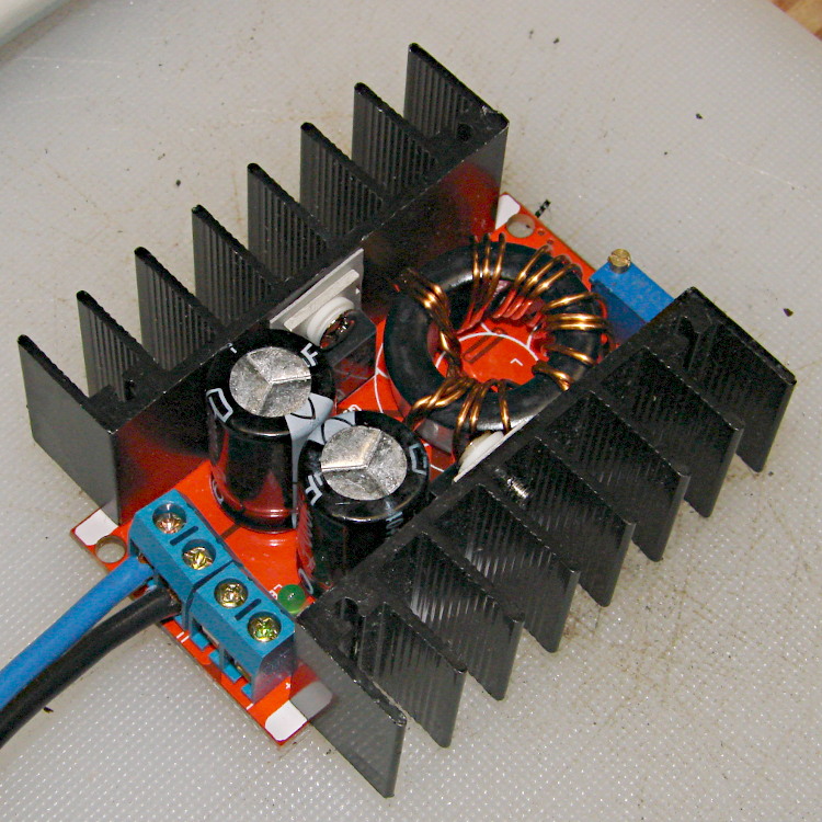
For reasons that will become apparent in a while, I got a pair (*) of boost power supplies from the usual eBay source, allegedly capable of boosting a 10-to-32 VDC input to a 12-to-35 VDC output, up to 10 A and 150 W:
Boost power supply
After establishing that it would not produce 30 V into a 5.9 Ω load (5.1 A, but 152 W), I got systematic.
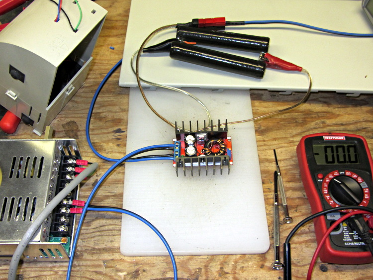
A 100 Ω resistor drew 1/4 A while I set the output to 28 V. Doubling up the resistors showed that it worked OK at half an amp:
Boost supply – 50 ohm load
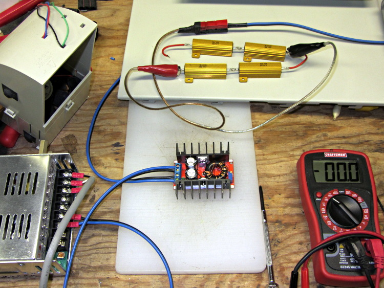
Four 6 Ω resistors in series draw 1.2 A, then (channeling the true spirit of DIY 3D printing) two in series drew 2.3 A:
Boost supply – 12 ohm load
That’s 32 W each and, yes, they did get toasty, but, no, I didn’t leave them turned on all that long.
But a 6 Ω resistance still didn’t work, so the supply can’t provide 4.7 A at 130 W. In case you were wondering, that’s two 6 Ω resistors in series and a pair of those strings in parallel, so each resistor still sees 32 W.
In terms of driving the actual load, these supplies aren’t going to light it up.
Ah, well, whaddaya want for five buck from halfway around the planet?
(*) Davy’s Aphorism: Never buy only one of any surplus item, because you’ll never find another. Get at least two, maybe three if it’s something you might actually use.
The cutter is still attached to the raft that, it seems, is required for passable results on the Afinia’s platform.
Having already figured out how to wrap a cutter around a shape, the most straightforward procedure starts by extracting the cutter’s shape. So, lay the cutter face down on the scanner and pull an image into GIMP:
Afinia Robot – scan
Blow out the contrast to eliminate the background clutter, then posterize to eliminate shadings:
Afinia Robot – scan enhanced
Select the black interior region, grow the selection by a pixel or two, then shrink it back to eliminate (most of) the edge granularity, plunk it into a new image, and fill with black:
Afinia Robot – scan filled
Now the magic happens…
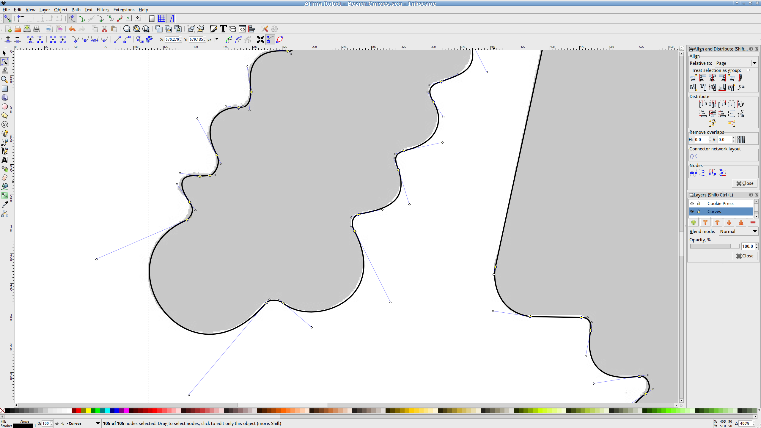
Import the bitmap image into Inkscape. In principle, you can auto-trace the bitmap outline and clean it up manually, but a few iterations of that convinced me that it wasn’t worth the effort. Instead, I used Inkscape’s Bézier Curve tool to drop nodes (a.k.a. control points) at all the inflection points around the image, then warped the curves to match the outline:
Afinia Robot – Bezier spline fitting
If you’re doing that by hand, you could start with the original scanned image, but the auto-trace function works best with a high-contrast image and, after you give up on auto-tracing, you’ll find it’s easier to hand-trace a high-contrast image.
Anyhow, the end result of all that is a smooth path around the outline of the shape, without all the gritty details of the pixelated version. Save it as an Inkscape SVG file for later reference.
OpenSCAD can import a painfully limited subset of DXF files that, it seems, the most recent versions of Inkscape cannot produce (that formerly helpful tutorial being long out of date). Instead, I exported (using “Save as”) the path from Inkscape to an Encapsulated Postscript file (this is a PNG, as WordPress doesn’t show EPS files):
Afinia Robot – Bezier Curves.eps
It’s not clear what the EPS file contains; I think it’s just a list of points around the path that doesn’t include the smooth Bézier goodness. That may account for the grittiness of the next step, wherein the pstoedit utility converts the EPS file into a usable DXF file:
Unfortunately, either the EPS file doesn’t have enough points on each curve or pstoedit automatically sets the number of points and doesn’t provide an override: contrary to what you (well, I) might think, the -splineprecision option doesn’t apply to whatever is in the EPS file. In any event, the resulting DXF file has rather low-res curves, but they were good enough for my purposes and OpenSCAD inhaled the DXF and emitted a suitable STL file:
Afinia Robot – shape slab
To do that, you set the Layout variable to “Slab”, compile the model, and export the STL.
Being interested only in the process and its results, not actually cutting and baking cookies, I tweaked the OpenSCAD parameters to produce stumpy “cutters”:
Afinia Robot – solid model
You do that by setting the Layout variable to “Build”, compile the model, and export yet another STL. In the past, this seemed to be a less fragile route than directly importing and converting the DXF at each stage, but that may not be relevant these days. In any event, having an STL model of the cookie may be useful in other contexts, so it’s not entirely wasted effort.
Run the STL through Slic3r to get the G-Code as usual.
The resulting model printed in about 20 minutes apiece on the M2:
Robot Cutter – stumpy version
As it turns out, the fact that the M2 can produce ready-to-use cutters, minus the raft, is a strong selling point.
Given a workable model, the next step was to figure out the smallest possible two-thread-wide cutter blade, then run variations of the Extrusion Factor to see how that affected surface finish. More on that in a while.
The OpenSCAD source isn’t much changed from the original Tux Cutter; the DXF import required different scale factors:
// Robot cookie cutter using Minkowski sum
// Ed Nisley KE4ZNU - Sept 2011
// August 2013 adapted from the Tux Cutter

Layout = "Build";				// Build Slab

//- Extrusion parameters - must match reality!

ThreadThick = 0.25;
ThreadWidth = 0.40;

function IntegerMultiple(Size,Unit) = Unit * ceil(Size / Unit);

MaxSize = 150;				// larger than any possible dimension ...

Protrusion = 0.1;

//- Cookie cutter parameters

Size = 95;

TipHeight = IntegerMultiple(3.0,ThreadThick);
TipThick = 1.5*ThreadWidth;			// 1.5* = thinnest 2-thread wall, 1.0* thread has gaps

WallHeight = IntegerMultiple(1.0,ThreadThick);
WallThick = 4.5*ThreadWidth;

LipHeight = IntegerMultiple(1.0,ThreadWidth);
LipThick = IntegerMultiple(5,ThreadWidth);

//- Wrapper for the shape of your choice

module Shape(Size) {
  Robot(Size);
}

//- A solid slab of Tux goodness in simple STL format
// Choose magic values to:
//		center it in XY
//		reversed across Y axis (prints with handle on bottom)
//		bottom on Z=0
//		make it MaxSize from head to feet

module Tux(Scale) {
  STLscale = 250;
  scale(Scale/STLscale)
	translate([105,-145,0])
	  scale([-1,1,24])
		import(
		  file = "/mnt/bulkdata/Project Files/Thing-O-Matic/Tux Cookie Cutter/Tux Plate.stl",
		  convexity=5);
}

module Robot(Scale) {
    STLscale = 100.0;
    scale(Scale / STLscale)
			scale([-1,1,10])
				import("/mnt/bulkdata/Project Files/Thing-O-Matic/Pinkie/M2 Challenge/Afinia Robot.stl",
					convexity=10);
}

//- Given a Shape(), return enlarged slab of given thickness

module EnlargeSlab(Scale, WallThick, SlabThick) {

	intersection() {
	  translate([0,0,SlabThick/2])
		cube([MaxSize,MaxSize,SlabThick],center=true);
	  minkowski(convexity=5) {
		Shape(Scale);
		cylinder(r=WallThick,h=MaxSize,$fn=16);
	  }
	}

}

//- Put peg grid on build surface

module ShowPegGrid(Space = 10.0,Size = 1.0) {

  RangeX = floor(100 / Space);
  RangeY = floor(125 / Space);

	for (x=[-RangeX:RangeX])
	  for (y=[-RangeY:RangeY])
		translate([x*Space,y*Space,Size/2])
		  %cube(Size,center=true);

}

//- Build it

ShowPegGrid();

if (Layout == "Slab")
	Shape(Size);

if (Layout == "Build")
	difference() {
	union() {
		translate([0,0,(WallHeight + LipHeight - Protrusion)])
		EnlargeSlab(Size,TipThick,TipHeight + Protrusion);
		translate([0,0,(LipHeight - Protrusion)])
		EnlargeSlab(Size,WallThick,(WallHeight + Protrusion));
		EnlargeSlab(Size,LipThick,LipHeight);
	}
	Shape(Size);					// punch out cookie hole
	}
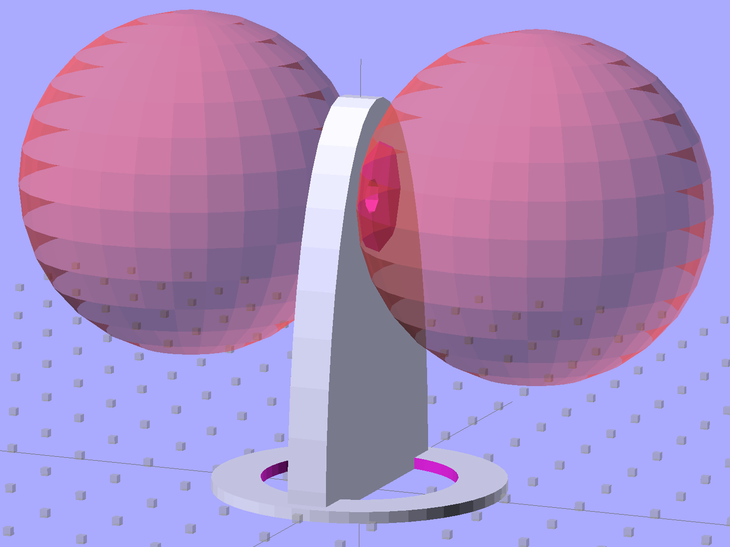
Then generate the sphere (well, two spheres, one for each dent) and offset it to scoop out the dent:
for (i=[-1,1]) {
translate([i*(DentSphereRadius + HandleThick/2 - DentDepth),0,StringHeight])
sphere(r=DentSphereRadius);
HandleThick controls exactly what you’d expect. StringHeight sets the location of the hole punched through the handle for a string, which is also the center of the dents.
The spheres have many facets, but only a few show up in the dent. I like the way the model looks, even if the facets don’t come through clearly in the plastic:
Quilting circle template – handle dent closeup – solid model
It Just Works and the exact math produces a better result than by-guess-and-by-gosh positioning.
The sphere radius will come out crazy large for very shallow dents. Here’s the helmet plate for my Bicycle Helmet Mirror Mount, which has an indentation (roughly) matching the curve on the side of my bike helmet:
Helmet mirror mount – plate
Here’s the sphere that makes the dent, at a somewhat different zoom scale:
Helmet mirror mount – plate with sphere
Don’t worry: trust the math, because It Just Works.
You find equations like that in Thomas Glover’s invaluable Pocket Ref. If you don’t have a copy, fix that problem right now; I don’t get a cut from the purchase, but you’ll decide you owe me anyway. Small, unmarked bills. Lots and lots of small unmarked bills…
Mary just started an ambitious pieced quilt that requires 50-some-odd precisely sized 1-1/2 inch circles, with marks to locate a 1 inch circle in the middle. She started using a drafting template to mark the smaller circle on freezer paper (don’t ask, it’s complicated), but we couldn’t find the template I know I have with the larger circles.
So I says to my wife, I sez, “Hey, we have the technology. What would really simplify what you’re doing?” After a bit of doodling, we came up with a ring having the proper ID and OD, plus a flat handle of some sort.
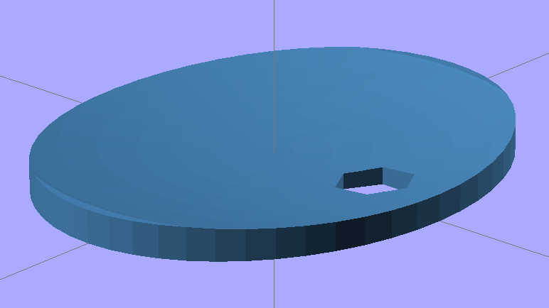
Half an hour later, I had a solid model:
Quilting circle template – solid model
An hour after that I handed her a warm piece of plastic:
Quilting circle template
The bottom ring is exactly 1-1/2 inch OD, 1 inch ID, and thin enough to draw around. The handle keeps her fingers out of the way and even has grips and a hole for a string.
The print quality near the hole isn’t as good as I’d like, because the slicer turned that entire volume into a solid slab of plastic. I can fix that in the second version, but right now she has something to work with, evaluate, and figure out what would improve it.
3D printing isn’t for everybody, but it’s a vital part of my shop!
The OpenSCAD source code has parameters for everything, so we can crank out more templates without fuss:
// Quilting - Circle Template
// Ed Nisley KE4ZNU - July 2013
Layout = "Show"; // Show Build Circle Handle
//-------
//- Extrusion parameters must match reality!
// Print with 2 shells
ThreadThick = 0.25;
ThreadWidth = 0.40;
HoleFinagle = 0.2;
HoleFudge = 1.00;
function HoleAdjust(Diameter) = HoleFudge*Diameter + HoleFinagle;
Protrusion = 0.1; // make holes end cleanly
function IntegerMultiple(Size,Unit) = Unit * ceil(Size / Unit);
function IntegerMultipleMin(Size,Unit) = Unit * floor(Size / Unit);
inch = 25.4;
//-------
// Dimensions
CircleID = (1) * inch;
SeamAllowance = (1/4) * inch;
CircleOD = CircleID + 2*SeamAllowance;
CircleThick = 6*ThreadThick;
CircleSides = 12*4;
HandleHeight = (2) * inch;
HandleThick = IntegerMultiple(5.0,ThreadWidth);
HandleSides = 12*4;
StringDia = 4.0;
StringSides = 8;
StringHeight = 0.75*HandleHeight;
DentDepth = HandleThick/4;
DentDia = 15.0;
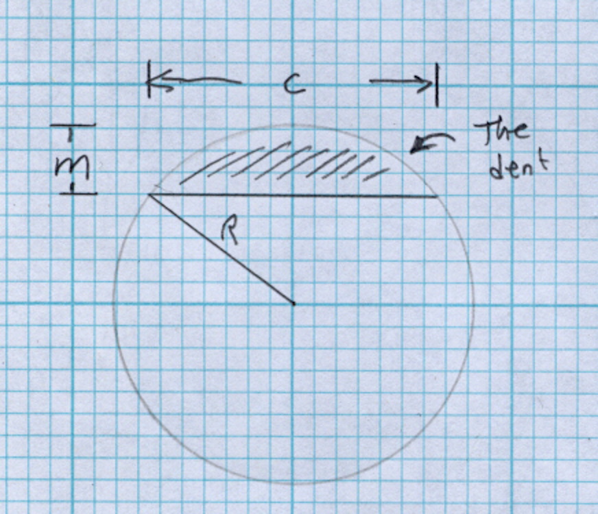
DentSphereRadius = (pow(DentDepth,2) + pow(DentDia,2)/4)/(2*DentDepth);
//-------
module PolyCyl(Dia,Height,ForceSides=0) { // based on nophead's polyholes
Sides = (ForceSides != 0) ? ForceSides : (ceil(Dia) + 2);
FixDia = Dia / cos(180/Sides);
cylinder(r=HoleAdjust(FixDia)/2,h=Height,$fn=Sides);
}
module ShowPegGrid(Space = 10.0,Size = 1.0) {
RangeX = floor(100 / Space);
RangeY = floor(125 / Space);
for (x=[-RangeX:RangeX])
for (y=[-RangeY:RangeY])
translate([x*Space,y*Space,Size/2])
%cube(Size,center=true);
}
//-------
// Circle ring plate
module CircleRing() {
rotate(180/CircleSides)
difference() {
cylinder(r=CircleOD/2,h=CircleThick,$fn=CircleSides);
translate([0,0,-Protrusion])
cylinder(r=CircleID/2,h=(CircleThick + 2*Protrusion),$fn=CircleSides);
}
}
//-------
// Handle
module Handle() {
difference() {
rotate([0,90,0])
scale([HandleHeight/(CircleOD/2),0.9,1])
rotate(180/HandleSides)
cylinder(r=CircleOD/2,h=HandleThick,center=true,$fn=HandleSides);
translate([0,0,-HandleHeight])
cube([2*CircleOD,2*CircleOD,2*HandleHeight],center=true);
translate([-HandleThick,0,StringHeight])
rotate([0,90,0])
rotate(180/StringSides)
PolyCyl(StringDia,2*HandleThick,StringSides);
# for (i=[-1,1]) {
translate([i*(DentSphereRadius + HandleThick/2 - DentDepth),0,StringHeight])
sphere(r=DentSphereRadius);
}
}
}
module Template() {
CircleRing();
Handle();
}
//-------
// Build it!
ShowPegGrid();
if (Layout == "Circle")
CircleRing();
if (Layout == "Handle")
Handle();
if (Layout == "Show")
Template();
I put the XY coordinate origin in the middle of the platform, so that laying objects out for printing doesn’t require knowing how large the platform will be: as long as the printer is Big Enough, you (well, I) can print without further attention.
The RepRap world puts the XY coordinate origin in the front left corner of the platform, so that the platform size sets the maximum printable coordinates and all printing happens in Quadrant I. This has the (major, to some folks) advantage of using only positive coordinates, while requiring an offset for each different platform.
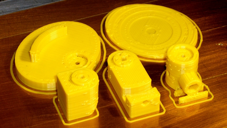
Yes, depending on which printer software you use, you can (automagically) center objects on your platform; this is often the only way to find objects created with Trimble (formerly Google) Sketchup. I am a huge fan of knowing exactly what’s going to happen before the printing starts, so I position my solid models exactly where I want them, right from the start. For example, this OpenSCAD model of the bike helmet mirror parts laid out for printing:
Helmet mirror mount – 3D model – Show layout
… exactly matches the plastic on the Thing-O-Matic’s platform, with the XY origin right down the middle of the platform:
Helmet mirror mount on build platform – smaller mirror shaft
It’d print exactly the same, albeit with more space around the edges, on the M2’s platform.
Similarly, the Z axis origin sits exactly on the surface of the platform. That way, the Z axis coordinate equals the actual height of the current thread extrusion in a measurable way: when you set the Z axis to, say, 2.0 mm, you can measure that exact distance between the extruder nozzle and the platform:
Taper gauge below nozzle
Now, admittedly, I fine-tune that distance by measuring the height of the skirt thread around the printed object, but the principle remains: a thread printed on the platform with Z=0.25 should be exactly 0.25 mm thick.
The start.gcode file handles all that:
;-- Slic3r Start G-Code for M2 starts --
;  Ed Nisley KE4NZU - 15 April 2013
M140 S[first_layer_bed_temperature]	; start bed heating
G90				; absolute coordinates
G21				; millimeters
M83				; relative extrusion distance
M84				; disable stepper current
G4 S3			; allow Z stage to freefall to the floor
G28 X0			; home X
G92 X-95			; set origin to 0 = center of plate
G1 X0 F30000		; origin = clear clamps on Y
G28 Y0			; home Y
G92 Y-127 		; set origin to 0 = center of plate
G1 Y-125 F30000	; set up for prime at front edge
G28 Z0			; home Z
G92 Z1.0			; set origin to measured z offset
M190 S[first_layer_bed_temperature]	; wait for bed to finish heating
M109 S[first_layer_temperature]	; set extruder temperature and wait
G1 Z0.0 F2000		; plug extruder on plate
G1 E10 F300		; prime to get pressure
G1 Z5 F2000		; rise above blob
G1 X5 Y-122 F30000	; move away from blob
G1 Z0.0 F2000		; dab nozzle to remove outer snot
G4 P1			; pause to clear
G1 Z0.5 F2000		; clear bed for travel
;-- Slic3r Start G-Code ends --
The wipe sequence, down near the bottom, positions the extruder at the front center edge of the glass plate, waits for it to reach the extrusion temperature, then extrudes 10 mm of filament to build up pressure behind the nozzle. The blob generally hangs over the edge of the platform and usually doesn’t follow the nozzle during the next short move and dab to clear the mess:
M2 – Wipe blobs on glass platform
I’ve also configured Slic3r to extrude at least 25 mm of filament in at least three passes around the object. After that, the extruder pressure has stabilized and the first layer of the object begins properly.
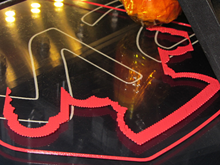
Which brings up another difference: the first layer printed on the platform is exactly like all the others. It’s not smooshed to get better adhesion or overfilled to make the threads stick together:
Robot cookie cutter – printing first layer
I print the first layer at 25 mm/s to give the plastic time to bond to the platform and use hairspray to make PLA stick to glass like it’s glued down.
I think the exported config.ini file corresponds to the currently selected set of sub-configurations; I find it difficult to keep a myriad of selections up-to-date while tweaking things, so mostly I don’t bother with named configurations.
The start.gcode and end.gcode lines go on forever, with embedded newlines.
# generated by Slic3r 0.9.11-dev on Mon Jul 22 09:28:22 2013
avoid_crossing_perimeters =
bed_size = 190,250
bed_temperature = 70
bottom_solid_layers = 3
bridge_acceleration = 0
bridge_fan_speed = 100
bridge_flow_ratio = 1
bridge_speed = 150
brim_width = 0
complete_objects = 0
cooling = 1
default_acceleration = 0
disable_fan_first_layers = 0
duplicate = 1
duplicate_distance = 6
duplicate_grid = 1,1
end_gcode = ;-- Slic3r End G-Code for M2 starts --\n;  Ed Nisley KE4NZU - March 2013\nM104 S0		; drop extruder temperature\nM140 S0		; drop bed temperature\nM106 S0		; bed fan off\nG1 Z180 F2000	; lower bed\nG1 X0 Y0 F30000	; center nozzle\nM84     	; disable motors\n;-- Slic3r End G-Code ends --
external_perimeter_speed = 50
external_perimeters_first = 0
extra_perimeters = 1
extruder_clearance_height = 20
extruder_clearance_radius = 20
extruder_offset = 0x0
extrusion_axis = E
extrusion_multiplier = .99
extrusion_width = 0.40
fan_always_on = 0
fan_below_layer_time = 45
filament_diameter = 1.72
fill_angle = 45
fill_density = 0.15
fill_pattern = honeycomb
first_layer_bed_temperature = 70
first_layer_extrusion_width = 0
first_layer_height = 100%
first_layer_speed = 25
first_layer_temperature = 175
g0 = 0
gap_fill_speed = 50
gcode_arcs = 0
gcode_comments = 0
gcode_flavor = reprap
infill_acceleration = 0
infill_every_layers = 1
infill_extruder = 1
infill_extrusion_width = 0
infill_first = 1
infill_only_where_needed = 1
infill_speed = 125
layer_gcode =
layer_height = 0.25
max_fan_speed = 100
min_fan_speed = 45
min_print_speed = 15
min_skirt_length = 25
notes =
nozzle_diameter = 0.35
only_retract_when_crossing_perimeters = 1
output_filename_format = [input_filename_base].gcode
overhangs = 1
perimeter_acceleration = 0
perimeter_extruder = 1
perimeter_extrusion_width = 0
perimeter_speed = 100
perimeters = 1
post_process =
print_center = 0,0
raft_layers = 0
randomize_start = 1
resolution = 0
retract_before_travel = 0.5
retract_layer_change = 0
retract_length = 1
retract_length_toolchange = 5
retract_lift = 0
retract_restart_extra = 0
retract_restart_extra_toolchange = 0
retract_speed = 80
rotate = 0
scale = 1
skirt_distance = 5
skirt_height = 1
skirts = 3
slowdown_below_layer_time = 20
small_perimeter_speed = 25
solid_fill_pattern = rectilinear
solid_infill_below_area = 15
solid_infill_every_layers = 0
solid_infill_extrusion_width = 0
solid_infill_speed = 100
spiral_vase = 0
start_gcode = ;-- Slic3r Start G-Code for M2 starts --\n;  Ed Nisley KE4NZU - 15 April 2013\nM140 S[first_layer_bed_temperature]	; start bed heating\nG90				; absolute coordinates\nG21				; millimeters\nM83				; relative extrusion distance\nM84				; disable stepper current\nG4 S3			; allow Z stage to freefall to the floor\nG28 X0			; home X\nG92 X-95			; set origin to 0 = center of plate\nG1 X0 F30000		; origin = clear clamps on Y\nG28 Y0			; home Y\nG92 Y-127 		; set origin to 0 = center of plate\nG1 Y-125 F30000	; set up for prime at front edge\nG28 Z0			; home Z\nG92 Z1.0			; set origin to measured z offset\nM190 S[first_layer_bed_temperature]	; wait for bed to finish heating\nM109 S[first_layer_temperature]	; set extruder temperature and wait\nG1 Z0.0 F2000		; plug extruder on plate\nG1 E10 F300		; prime to get pressure\nG1 Z5 F2000		; rise above blob\nG1 X5 Y-122 F30000	; move away from blob\nG1 Z0.0 F2000		; dab nozzle to remove outer snot\nG4 P1			; pause to clear\nG1 Z0.5 F2000		; clear bed for travel\n;-- Slic3r Start G-Code ends --
start_perimeters_at_concave_points = 1
start_perimeters_at_non_overhang = 1
support_material = 0
support_material_angle = 0
support_material_enforce_layers = 0
support_material_extruder = 1
support_material_extrusion_width = 0
support_material_interface_layers = 0
support_material_interface_spacing = 0
support_material_pattern = rectilinear
support_material_spacing = 2.5
support_material_speed = 125
support_material_threshold = 0
temperature = 175
thin_walls = 1
threads = 2
toolchange_gcode =
top_infill_extrusion_width = 0
top_solid_infill_speed = 50
top_solid_layers = 3
travel_speed = 250
use_relative_e_distances = 0
vibration_limit = 0
wipe = 0
z_offset = 0