The Smell of Molten Projects in the Morning

Ed Nisley's Blog: Shop notes, electronics, firmware, machinery, 3D printing, laser cuttery, and curiosities. Contents: 100% human thinking, 0% AI slop.

Tag: M2

Using and tweaking a Makergear M2 3D printer

  • Toyota Sienna Hood Rod Pivot

    We don’t drive the van nearly often enough (*) to keep the battery charged in cold weather, so I use a trickle charger to keep it alive between jaunts. While opening the hood one evening, I managed to twist the plastic fitting that anchors the hood prop rod beyond its limits and snapped the poor thing off, which left me holding the hood in one hand and the rod in the other.

    After extricating most of the fragments from under the van, I found that the OEM part had a hollow post that snapped into a square hole in the front bulkhead under the hood. The post had two keys and a pair of snap latches that held it in place, a design that seemed optimized for rapid assembly with no fiddly parts, but which depended on a few millimeters of plastic to restrain a meter of steel rod.

    I made up a simple replacement with a solid square post and a square cap to clamp it against the bulkhead:

    Toyota Sienna hood rod pivot - first version
    Toyota Sienna hood rod pivot – first version

    The general idea is that the screw puts the entire post under compression, giving it less temptation to shear at the deck line when I twist the rod a bit too far out of line. That 8-32 screw seemed entirely adequate to the task; a 10-32 screw would take up too much of the post for my liking.

    Alas, it turns out that underneath the bulkhead’s top flange lies a metal plate surrounding the headlight that’s so close to the hole that the big blocky cap wouldn’t fit. So I slimmed the cap down to three thread widths and tried again, only to discover that the plate came that close to the edge of square hole.

    However, there was a gap between the bottom of the bulkhead and the top of the plate, so I introduced pivot and cap to Mr Belt Sander, removed enough plastic to let the cap slide into the gap, then discovered the 8-32 screw head was just slightly too large to let the screw align with the post.

    Another tweak to the model, based on actual measurements on the abused parts, produced the final version:

    Toyota Sienna Hood Rod Pivot - solid model
    Toyota Sienna Hood Rod Pivot – solid model

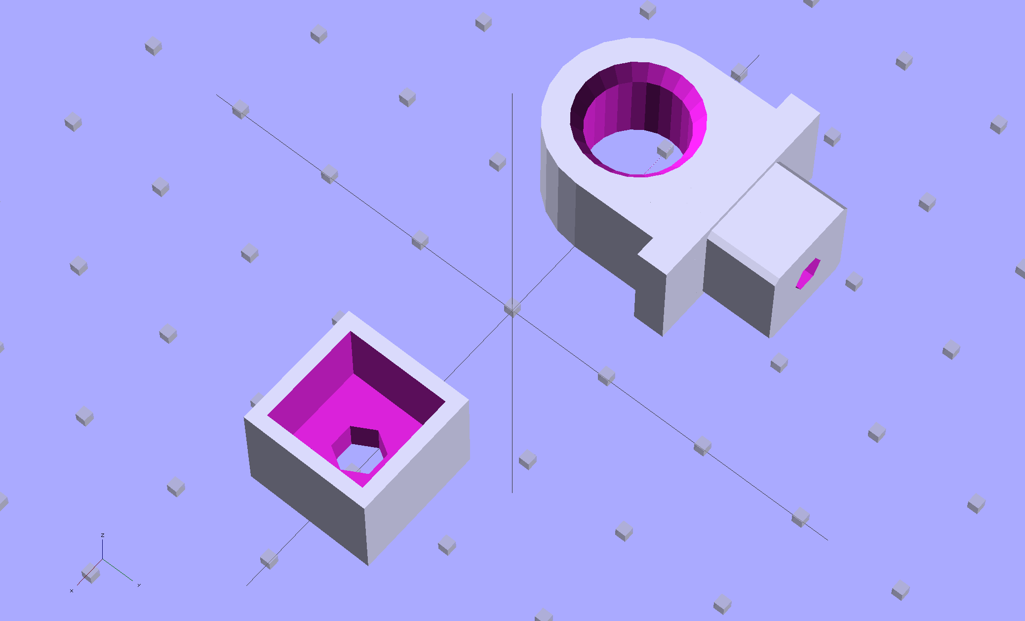
    The rod hole has a nice bevel, there’s no fragile neck between the rod hole and the base flange, the solid post lies flat on the platform for EZ building, and there’s a slight offset between the post and the flange that eliminates the need for support material. Printing it lying down orients the filament paths around the hole and base, making the part stronger in the direction it needs the most strength.

    I think the cap walls could be slightly thicker, but we’ll see how long the thing lasts…

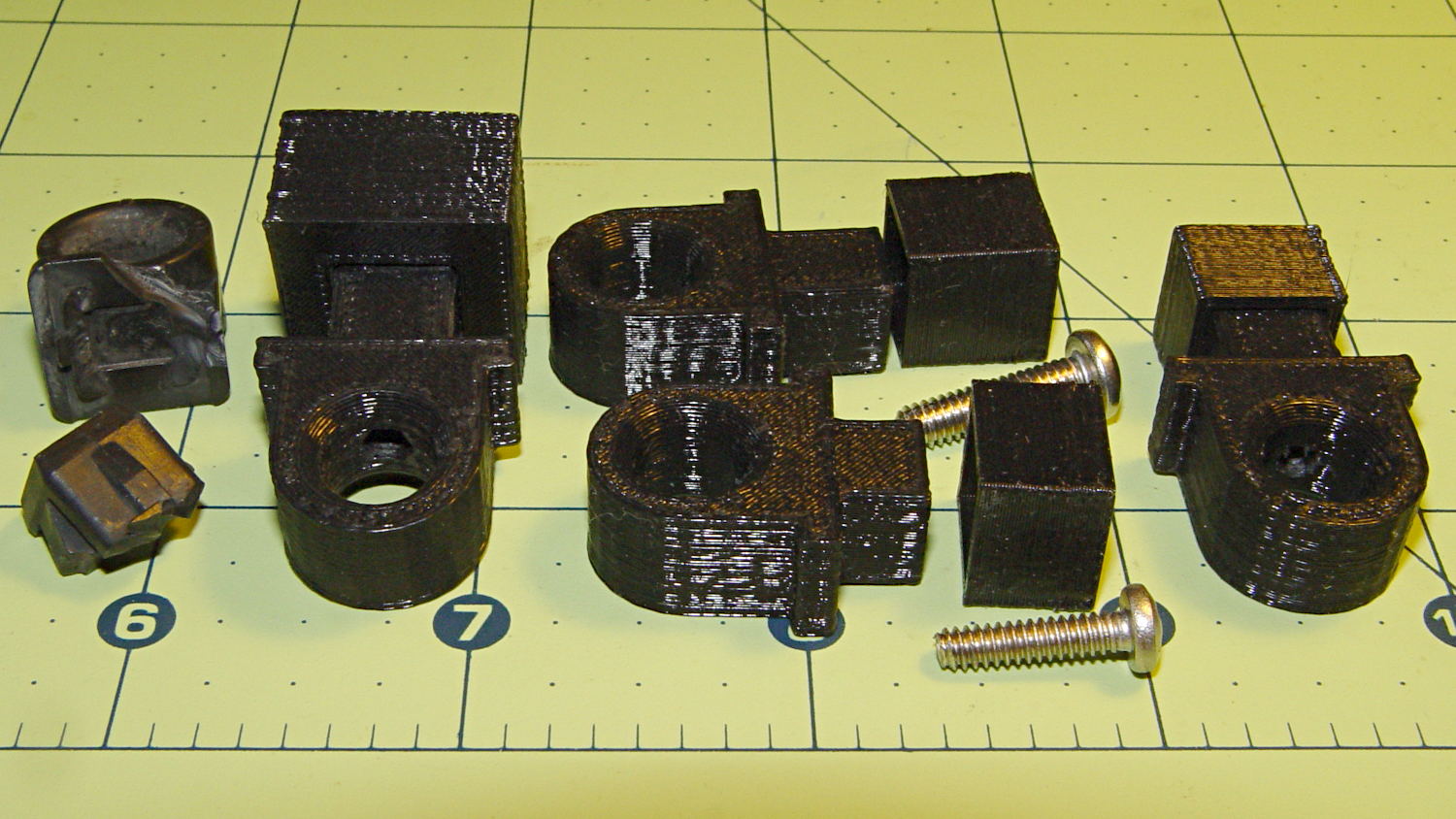
    A group photo of all the versions, lined up from left to right, shows the broken OEM part, the first blocky attempt, the slimmed-down and too-long version to the rear, the shorter version that actually fit, and a backup part for when that one breaks:

    Toyota Sienna hood rod pivot versions
    Toyota Sienna hood rod pivot versions

    The sanded-down part held the hood open while I took that group picture. Here’s what it looks like under load:

    Toyota Sienna hood rod pivot - in place
    Toyota Sienna hood rod pivot – in place

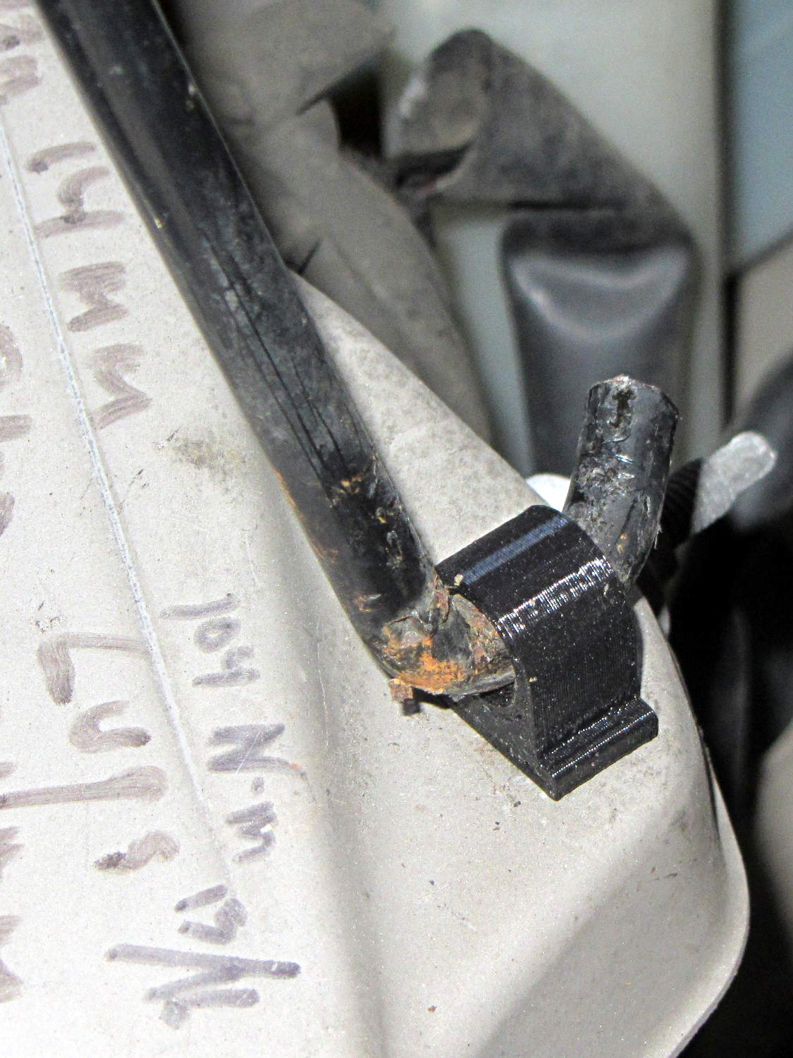
    The scrawls on the bulkhead just in front of the pivot remind me of fluid levels, torques, and suchlike. The stud sticking out to the rear is a headlight aiming screw mounted in the plate that caused so much hassle; you’d think I’d have noticed it before starting this adventure, but noooo

    For what it’s worth, that’s rapid prototyping in action: three (and a half) iterations in quick succession, each getting closer to a goal that you (well, I) can’t quite define, but will recognize when it appears. Took about three hours over the course of two days.

    I loves me my M2 3D printer…

    (*) Indeed, the tires often take three miles to warm up their flat spots due to sitting in the garage for a week…

  • HP Scope Probe Flange Repair: Improved Spares

    While reducing the clutter atop the Electronics Workbench, I ran off four more probe flange reinforcements, just so I’m ready for the next crunch:

    HP scope probe flange disks
    HP scope probe flange disks

    They’re almost identical to the previous version, although I tweaked the taper to end slightly inside the cylindrical cup, thereby eliminating the coincident faces and leaving a minute rim that doesn’t matter:

    HP Scope Probe Flange Repair - bottom
    HP Scope Probe Flange Repair – bottom

    Given that I’ve had the ‘scope for nigh onto two decades and have only broken one probe flange, I think four reinforcements will be a lifetime supply: with any luck, the scope will blow a capacitor before I do.

    The OpenSCAD source code:

    // Tek Scope Probe Flange
    // Ed Nisley KE4ZNU November 2013
    
    //- Extrusion parameters must match reality!
    //  Print with 2 shells and 3 solid layers
    
    ThreadThick = 0.20;
    ThreadWidth = 0.40;
    
    HoleWindage = 0.2;
    
    Protrusion = 0.1;            // make holes end cleanly
    
    function IntegerMultiple(Size,Unit) = Unit * ceil(Size / Unit);
    
    //----------------------
    // Dimensions
    
    FlangeOD = 16.0;
    FlangeID = 8.75;
    FlangeThick = IntegerMultiple(1.25,ThreadThick);
    
    DiskOD = FlangeOD + 4*ThreadWidth;
    DiskThick = FlangeThick + 4*ThreadThick;
    
    NumSides = 8*4;
    
    //----------------------
    // Useful routines
    
    module PolyCyl(Dia,Height,ForceSides=0) {            // based on nophead's polyholes
    
    Sides = (ForceSides != 0) ? ForceSides : (ceil(Dia) + 2);
    
    FixDia = Dia / cos(180/Sides);
    
    cylinder(r=(FixDia + HoleWindage)/2,
    h=Height,
    $fn=Sides);
    }
    
    module ShowPegGrid(Space = 10.0,Size = 1.0) {
    
    Range = floor(50 / Space);
    
    for (x=[-Range:Range])
    for (y=[-Range:Range])
    translate([x*Space,y*Space,Size/2])
    %cube(Size,center=true);
    
    }
    
    //----------------------
    // Build it
    
    ShowPegGrid();
    
    difference() {
    union() {
    translate([0,0,2*ThreadThick])
    cylinder(r=DiskOD/2,h=DiskThick,$fn=NumSides);    // cylinder around flange
    
    cylinder(r1=(DiskOD - 2*ThreadWidth)/2,                // flange reinforcing plate
    r2=DiskOD/2,
    h=(2*ThreadThick + Protrusion),
    $fn=NumSides);
    }
    translate([0,0,(DiskThick - FlangeThick)])                // flange clearance
    PolyCyl(FlangeOD,2*FlangeThick,NumSides);
    
    translate([0,0,-DiskThick/2])                            // probe nose clearance
    PolyCyl(FlangeID,2*DiskThick,NumSides);
    }
    
  • Marmorated Stink Bug Sighting

    Late in the fall, Brown Marmorated Stink Bugs move indoors to spend the winter; they can infiltrate through the smallest of cracks and seem to show up unannounced in the strangest locations. This one magically appeared on my M2 printer while I was starting it up:

    Brown Marmorated Stink Bug on M2 Printer
    Brown Marmorated Stink Bug on M2 Printer

    I unceremoniously flushed its contribution to the gene pool…

  • Solubility of PLA in Common Gun Bore Cleaners

    According to Wikipedia, Polylactic acid, a.k.a. PLA “is soluble in chlorinated solvents, hot benzene, tetrahydrofuran, and dioxane” and is not soluble in acetone, alcohol, or water.

    Just to see what happens, I dunked a pair of those 3D printed dummy bullets in Shooter’s Choice Gun Solvent (which has since gone obsolete) and Hoppe’s No. 9 Gun Bore Cleaner (which seems to have been reformulated several times), then let them air-dry in those background puddles:

    PLA dummy bullets after solvent bath
    PLA dummy bullets after solvent bath

    Nothing much happened: they’re not soft or gummy, haven’t slumped, and seem undaunted.

    That’s in contrast to ABS plastic, which is readily soluble in acetone and the aromatic hydrocarbons commonly found in solvents used around firearms. Apart from that, ABS would be a slightly better choice on mechanical grounds. I’m not sure the difference really matters for most purposes, given the very wide tolerances on 3D printed objects.

  • Dummy 9 mm Luger Cartridge: 100 μm Layers

    As you might expect, changing the layer thickness to 0.1 mm = 100 μm dramatically improves the appearance of the dummy 9 mm Luger bullet on the left, compared to the 0.25 mm = 250 μm layers on the right:

    Dummy 9 mm Luger cartridges - 0.1 mm layer - overview
    Dummy 9 mm Luger cartridges – 0.1 mm layer – overview

    The inside edge of the translucent skirt around the quartet measured 90 to 110 μm, so the layer height is spot on:

    Dummy 9 mm Luger bullets - 0.1 mm layer - overhead on platform
    Dummy 9 mm Luger bullets – 0.1 mm layer – overhead on platform

    That required no adjustments to the M2 at all; It Just Works. Admittedly, that’s with a custom platform and firm supports replacing the springs, plus better Z-axis homing, but the overall structure was fine to start with.

    I used the same Slic3r settings as before, with the only change being the layer thickness. Letting it pick the layer width might produce better results, but a 0.35 mm nozzle won’t go much narrower than 0.40 mm anyway.

    A closer look at the bullet show the thinner layers provide a better rendition of the stretched sphere forming the nose; it’s less pointy than the one assembled from thicker layers:

    Dummy 9 mm Luger bullets - 0.1 mm layer - side
    Dummy 9 mm Luger bullets – 0.1 mm layer – side

    The nose closes better with thinner layers:

    Dummy 9 mm Luger bullets - 0.1 mm layer - nose
    Dummy 9 mm Luger bullets – 0.1 mm layer – nose

    None of that really matters for this application, but it’s a useful data point.

    The downside is that printing with thinner layers requires more time: a single bullet (of 16) requires 2.2 minutes at 250 μm and (of 4) 9 minutes at 100 μm. The simple ratio of layer thicknesses predicts a factor of 2.5, not 4, but the skirt requires a larger fraction of the total time. The estimated time for a 4×4 array at 100 μm comes out at 5.2 minutes each, a factor of 2.4, which is close enough.

    Although 100 μm certainly looks better, it doesn’t really improve anything for most of the blocky stuff I make…

  • Dummy 9 mm Luger Cartridge

    An interesting project requires a handful of 9 mm Luger (aka 9 mm NATO) dummy cartridges with real brass. You can buy exact form / fit / weight dummies or plastic training rounds, but these will suit my simple needs:

    Dummy 9 mm Luger cartridges
    Dummy 9 mm Luger cartridges

    That’s a snap cap on the left and a real 9 mm Luger cartridge on the right. The holes in the dummy brass indicate that they are absolutely, positively, unquestionably not loaded cartridges.

    Start by drilling a 1/8 inch hole in the side of each unfired, primerless case:

    Dummy 9 mm Luger - drilling case
    Dummy 9 mm Luger – drilling case

    I set up the chuck on the rotary table, thinking I might drill three holes in each cartridge, but came to my senses. It’s lined up by eye, flush with the end of the jaws, and the hole is just above the inside of the base.

    The solid model has the same overall length and proportion as a 115 grain FMJ bullet, but doesn’t match the proper ogive or base diameter. Basically, I stretched a 9 mm sphere and stuck it atop a slightly tapered base cylinder:

    Dummy 9 mm Luger bullet - solid model
    Dummy 9 mm Luger bullet – solid model

    For reasons I don’t profess to understand, the sphere has a slightly different diameter at its equator than the top of the cylinder, even though they’re both the same BulletOD diameter with the same number of faces. Fortunately, that didn’t affect the final results.

    Print up a handful of the things:

    Dummy 9 mm Luger bullets - on platform
    Dummy 9 mm Luger bullets – on platform

    The shadow from the flash makes the bases look slightly fatter than they really are.

    Using a thinner layer would look better in this orientation. They’d definitely look better if they were split, printed with the long axis parallel to the plate, and glued together, as the grain would run lengthwise; I’m not sure there’s enough room for alignment pins, though.

    At this diameter and number of faces, the M2 produces almost perfectly accurate dimensions, so the bullets press-fit just like you’d expect. They’re twisted into a dab of urethane glue inside the brass that foams just enough to hold them place.

    Rather than use a real seating die, I deployed a closed chuck on the drill press. The trick is to set the depth stop to produce slightly too-long cartridges, then shim the platform without changing the stop and seat the bullet to the proper depth:

    Dummy 9 mm Luger - seating bullet
    Dummy 9 mm Luger – seating bullet

    The OAL tolerance for various 9 mm Luger cartridges seems to range from 1.08 inch to 1.17 inch, so anything in that range should be fine. I used 1.10 inch.

    These are not intended for firing. You could fire them with just a primer (in a non-drilled case) and (maybe) not melt or shatter the plastic, but they’re slightly larger than the nominal 8.82 mm land diameter and won’t obturate or spin-stabilize worth diddly: expect short range and keyholing.

    The sectional density is a whopping 0.008, should you keep track of such things: 0.47 gram = 7.2 grain. Note that the US small arms definition of sectional density has units of pound/inch2, not the pound/foot2 you’ll find right next to values computed using inches; the magic number 1/7000 just converts from grains to pounds. In the rest of the (metric) world, it’s entirely different.

    The OpenSCAD source code:

    // Dummy 9mm Luger bullet
    // Ed Nisley KE4ZNU November 2013
    
    //----------------------
    // Dimensions
    
    BulletOD = 9.05;			// main diameter
    BulletBaseOD = 8.8;			//  ... easy insertion
    
    BulletOAL = 14.0;			// overall length
    BaseLength = 8.0;			// cylindrical base length
    
    NoseLength = BulletOAL - BaseLength;
    
    NumSides = 8*4;
    
    //----------------------
    // Useful routines
    
    module ShowPegGrid(Space = 10.0,Size = 1.0) {
    
      Range = floor(50 / Space);
    
    	for (x=[-Range:Range])
    	  for (y=[-Range:Range])
    		translate([x*Space,y*Space,Size/2])
    		  %cube(Size,center=true);
    }
    
    //-------------------
    // Build it...
    
    ShowPegGrid();
    
    color("Orange")
    cylinder(r1=BulletBaseOD/2,r2=BulletOD/2,h=BaseLength,$fn=NumSides);
    
    color("DarkOrange")
    translate([0,0,BaseLength])
    	resize([0,0,2*NoseLength])
    		sphere(BulletOD/2,$fn=NumSides);
    
  • HP Scope Probe Flange Repair

    Quite some time ago I manage to break the finger flange on one of my scope probes and, what with it being made of an un-glueable engineering plastic, a simple repair job failed quickly. It’s entirely round and a perfect lathe project, but … this is easier:

    HP Scope Probe Flange Repair
    HP Scope Probe Flange Repair

    You can see remnants of that failed repair just below the fracture:

    HP scope probe flanges - repair disk
    HP scope probe flanges – repair disk

    Some epoxy around the rim of the flange, plus filling the missing sector, looks about as grubby as you’d expect:

    HP Scope Probes - rear
    HP Scope Probes – rear

    That’s a tiny zit at about 1 o’clock which came off with fingernail pressure.

    From the business end, it actually looks pretty snappy:

    HP Scope Probes - front
    HP Scope Probes – front

    I’m mildly tempted to preemptively reinforce the other probes…

    The OpenSCAD source code joins two parts with coincident faces, but it worked out OK for once:

    // Tek Scope Probe Flange
    // Ed Nisley KE4ZNU November 2013
    
    //- Extrusion parameters must match reality!
    //  Print with 2 shells and 3 solid layers
    
    ThreadThick = 0.25;
    ThreadWidth = 0.40;
    
    HoleWindage = 0.2;
    
    Protrusion = 0.1;			// make holes end cleanly
    
    function IntegerMultiple(Size,Unit) = Unit * ceil(Size / Unit);
    
    //----------------------
    // Dimensions
    
    FlangeOD = 16.0;
    FlangeID = 8.75;
    FlangeThick = IntegerMultiple(1.25,ThreadThick);
    
    DiskOD = FlangeOD + 4*ThreadWidth;
    DiskThick = FlangeThick + 4*ThreadThick;
    
    NumSides = 8*4;
    
    //----------------------
    // Useful routines
    
    module PolyCyl(Dia,Height,ForceSides=0) {			// based on nophead's polyholes
    
      Sides = (ForceSides != 0) ? ForceSides : (ceil(Dia) + 2);
    
      FixDia = Dia / cos(180/Sides);
    
      cylinder(r=(FixDia + HoleWindage)/2,
               h=Height,
    	   $fn=Sides);
    }
    
    module ShowPegGrid(Space = 10.0,Size = 1.0) {
    
      Range = floor(50 / Space);
    
    	for (x=[-Range:Range])
    	  for (y=[-Range:Range])
    		translate([x*Space,y*Space,Size/2])
    		  %cube(Size,center=true);
    
    }
    
    //----------------------
    // Build it
    
    ShowPegGrid();
    
    	difference() {
    		union() {
    			translate([0,0,2*ThreadThick])
    				cylinder(r=DiskOD/2,h=DiskThick,$fn=NumSides);			// main repair part
    			cylinder(r1=(DiskOD - 2*ThreadWidth)/2,r2=DiskOD/2,h=2*ThreadThick,$fn=NumSides);
    		}
    		translate([0,0,(DiskThick - FlangeThick)])				// flange clearance
    			PolyCyl(FlangeOD,2*FlangeThick,NumSides);
    		translate([0,0,-DiskThick/2])
    			PolyCyl(FlangeID,2*DiskThick,NumSides);
    	}