Ed Nisley's Blog: Shop notes, electronics, firmware, machinery, 3D printing, laser cuttery, and curiosities. Contents: 100% human thinking, 0% AI slop.
Clamping a long-stroke dial indicator to the M2’s X axis gantry:
Dial indicator – gantry to M2 Y rail
Then stuffing manual G-Code into Pronterface produced some data on Z-axis accuracy, repeatability, and hysteresis:
M2 Z-axis positioning measurements
Note that the commanded positions are in 0.001 mm units (25 = 0.025 mm) and the observed positions are in mils (1 = 0.001 inch). The arrows indicate which way the stage moved, with positive Z increments moving the stage down.
The overall distance seems to be quantized at 0.0150 mm = 6 step intervals. You can command a motion between those steps (G0 Z0.0025, G0 Z0.0075, etc), but the motor doesn’t turn until the distance exceeds the next interval (G0 Z0.0150 causes motion). This isn’t stiction, because the firmware isn’t activating the motor.
Stepping up and down in 0.025 mm increments (10 steps, but not an even multiple of the 6 step quantization intervals) over a 0.100 mm range produces about 0.01 mm = 4 steps of backlash. Some of that definitely comes from the quantization interval, but it’s not consistent, so there’s also mechanical backlash.
Frankly, that’s better than I expected, but any motion less than about 4 steps probably won’t happen and the errors are on the same order. Whether the firmware itself can compute and apply a smaller motion isn’t clear.
The controller doesn’t know where the platform is, at least in an open-loop stepper system. That means when the commanded motion is on the same order as the backlash, the controller can’t make the proper adjustments. As long as the positioning error remains smaller than the tolerance, it’s all good; expecting 0.020 mm resolution and accuracy seems reasonable.
But it’s only a quick-and-dirty test, so I wouldn’t read too much into it.
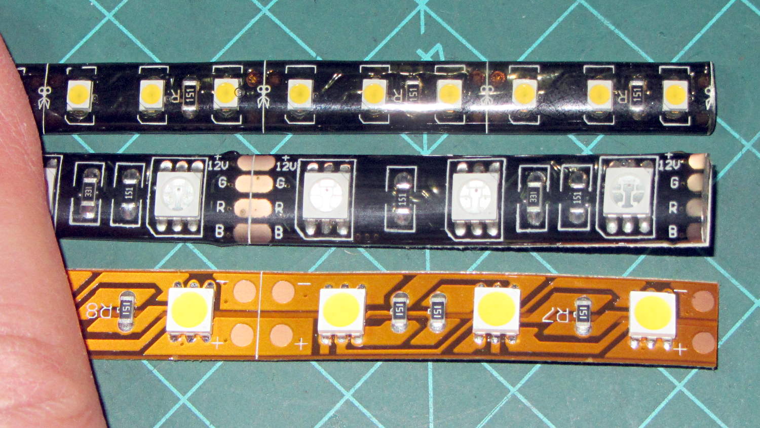
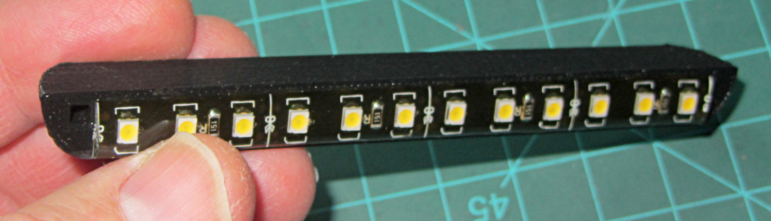
Solder pretty cable with silver plating on the braid (it’s probably mil-spec Teflon dielectric RG-174 coaxial cable) to the LEDs
Conjure a coax power connector and wall wart
Apply foam squares to mounts
Affix to sewing machine
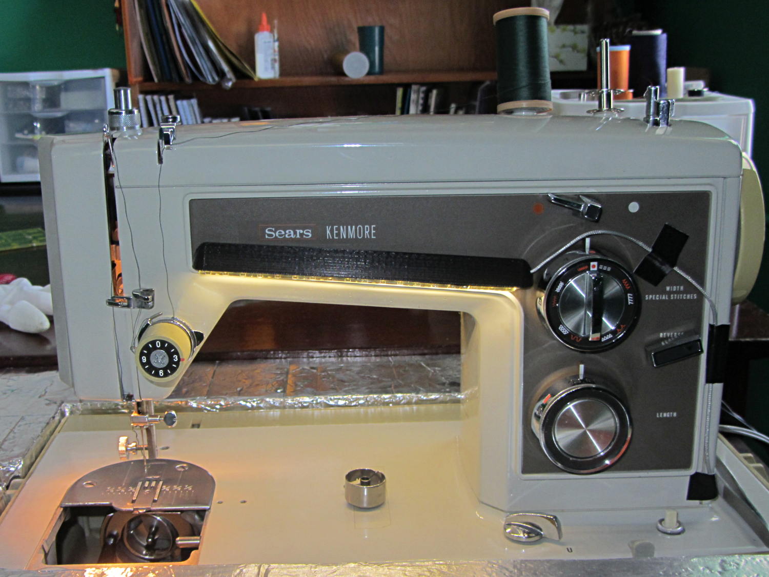
The front LEDs have a jaunty angle along the bottom of the plastic panel:
Kenmore Model 158 Sewing Machine – LED Lights – front
You can see why I want cool-white LEDs, rather than these warm-white ones, to match the daylight from the window to the right. The wash of orange light from the incandescent bulb inside the end bell has got to go, too.
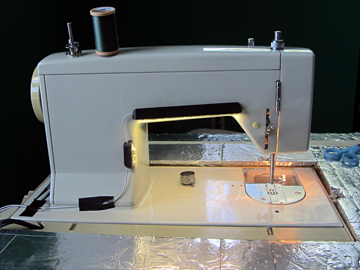
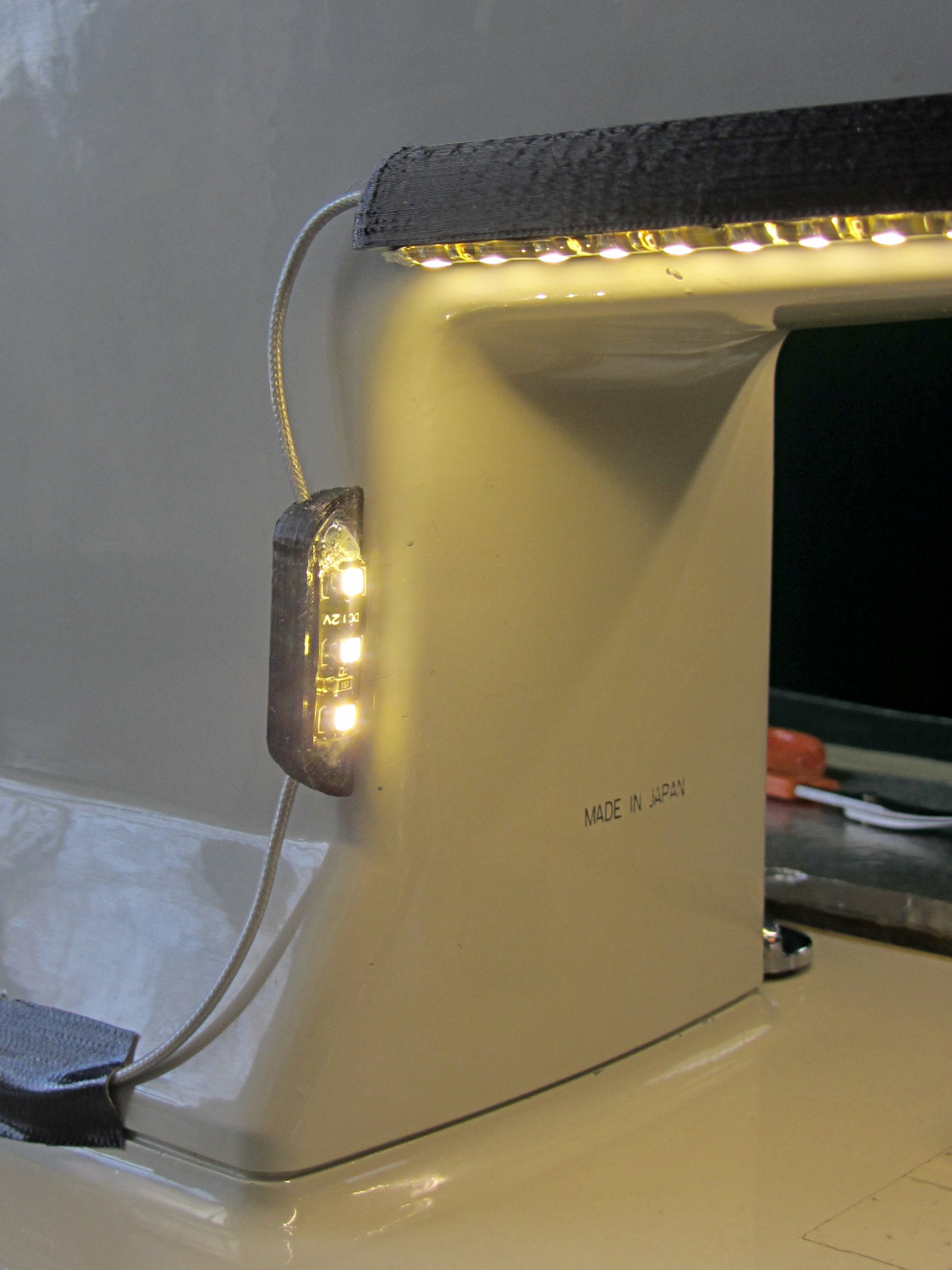
The rear LEDs over the arm may be slightly too close to the opening:
Kenmore Model 158 Sewing Machine – LED Lights – rear
The single-segment strip on the side provides a bit more light for the needle across the opening:
Kenmore Model 158 Sewing Machine – LED Lights – rear detail
Now, I’ll grant you that the strips of of black Gorilla Tape aren’t particularly attractive, but the intent here is to find out whether the LEDs produce enough light, don’t snag the quilt, and generally meet requirements.
My old Thing-O-Matic has new life as the Frank-O-Squid at Squidwrench Galactic HQ, with all the original Makerbot electronics replaced by an Azteeg X3 controller. Over the last several weeks I’ve coaxed it into doing most of the right things at the proper speeds & feeds, so we can now move on to actually making stuff:
Frank-o-Squid in action
The warping on that little digital caliper thumbwheel holder show that I don’t have the tiny-object slowdown settings quite correct, but it’s getting close.
The Marlin firmware is on GitHub. I intended to set it up so that pulling changes from upstream Marlin would be easy, but totally blundered something along the way. I’ll eventually plug the changes from Configuration.h, Configuration_adv.h, and pins.h into a clean branch and start over, but, for now, we’re slowly diverging from consensus reality.
Although the platform still has the Z-min switch over on the right edge, neither the firmware nor Slic3r pay any attention to it. A stub in the startup G-Code sequence does a head fake toward the switch, but doesn’t actually probe it.
I scrapped the original craptastic Makerbot ATX power supply and replaced it with Makergear’s huge 12 V laptop brick that powered the original M2 platform, so the thermal switches on the extruder no longer do anything useful; it’s running bare, pretty much like all other 3D printers.
The Slic3r configuration exports thusly:
# generated by Slic3r 1.0.0RC1 on Mon Mar  3 07:48:29 2014
avoid_crossing_perimeters = 0
bed_size = 105,120
bed_temperature = 100
bottom_solid_layers = 3
bridge_acceleration = 0
bridge_fan_speed = 100
bridge_flow_ratio = 1
bridge_speed = 40
brim_width = 1.0
complete_objects = 0
cooling = 1
default_acceleration = 0
disable_fan_first_layers = 1000
duplicate = 1
duplicate_distance = 6
duplicate_grid = 1,1
end_gcode = ;---- end.gcode starts ----\n; TOM 286 - Al plates + Geared extruder\n; Ed Nisley - KE4ZNU - January 2014\n; Marlin with tweaks for Azteeg X3 with thermocouple\n;- inhale filament blob\nG91\nG1 E-5 F900\nG90\n;- turn off heaters\nM104 S0         ; extruder head\nM140 S0         ; HBP\n;- move to eject position\nG0 Z115 F1000   ; home Z to get nozzle away from object\n;G92 Z115      ; reset Z\nG1 X0 F6000     ; center X axis\nG1 Y35          ; move Y stage forward\n;---- end.gcode ends ----
external_perimeter_speed = 50%
external_perimeters_first = 0
extra_perimeters = 1
extruder_clearance_height = 20
extruder_clearance_radius = 20
extruder_offset = 0x0
extrusion_axis = E
extrusion_multiplier = 0.95
extrusion_width = 0.50
fan_always_on = 0
fan_below_layer_time = 1
filament_diameter = 2.95
fill_angle = 45
fill_density = 0.15
fill_pattern = honeycomb
first_layer_acceleration = 0
first_layer_bed_temperature = 100
first_layer_extrusion_width = 0.50
first_layer_height = 0.25
first_layer_speed = 10
first_layer_temperature = 210
g0 = 0
gap_fill_speed = 30
gcode_arcs = 0
gcode_comments = 0
gcode_flavor = reprap
infill_acceleration = 0
infill_every_layers = 2
infill_extruder = 1
infill_extrusion_width = 0.50
infill_first = 1
infill_only_where_needed = 1
infill_speed = 50
layer_gcode =
layer_height = 0.25
max_fan_speed = 100
min_fan_speed = 35
min_print_speed = 10
min_skirt_length = 3
notes =
nozzle_diameter = 0.4
only_retract_when_crossing_perimeters = 1
ooze_prevention = 0
output_filename_format = [input_filename_base].gcode
overhangs = 1
perimeter_acceleration = 0
perimeter_extruder = 1
perimeter_extrusion_width = 0.50
perimeter_speed = 30
perimeters = 1
post_process =
print_center = 0,0
raft_layers = 0
randomize_start = 1
resolution = 0.05
retract_before_travel = 0.0
retract_layer_change = 0
retract_length = 0.75
retract_length_toolchange = 10
retract_lift = 0
retract_restart_extra = 0
retract_restart_extra_toolchange = 0
retract_speed = 30
rotate = 0
scale = 1
skirt_distance = 2
skirt_height = 1
skirts = 1
slowdown_below_layer_time = 30
small_perimeter_speed = 50%
solid_fill_pattern = rectilinear
solid_infill_below_area = 5
solid_infill_every_layers = 0
solid_infill_extrusion_width = 0.50
solid_infill_speed = 150%
spiral_vase = 0
standby_temperature_delta = -5
start_gcode = ;---- start.gcode begins ----\n; TOM 286 - Al plates + Geared extruder + Zmin platform sense\n; Ed Nisley - KE4ZNU - January 2014\n; Marlin with tweaks for Azteeg X3 with thermocouple\n;\n; Set initial conditions\nG21                 ; set units to mm\nG90                 ; set positioning to absolute\n;----------\n; Begin heating\nM104 S[first_layer_temperature]         ; extruder head\nM140 S[first_layer_bed_temperature]	; start bed heating\n;----------\n; Home axes\nG28 X0 Y0 Z0\nG92 X-53.5 Y-58.5 Z114.5\n;----------\n; Initial nozzle wipe to clear snot for Z touchoff\nG1 X0 Y0 Z3.0 F1000     ; pause at center to build confidence\nG4 P1000\nG1 Z10                  ; ensure clearance\nG1 X39 Y-58.0 F1000    ; move to front, avoid wiper blade\nG1 X55                  ; to wipe station\nG1 Z6.0                 ; to wipe level\nM116                    ; wait for temperature settling\nG1 Y-45 F500            ; slowly wipe nozzle\n;-----------------------------------------------\n; Z platform height touchoff\n; Make sure the XY position is actually over the switch!\n; Home Z downward to platform switch\n; Compensate for 0.05 mm backlash in G92: make it 0.05 too low\nG1 X56.0 Y8.2 F5000\nG1 Z4.0 F1000     ; get over build platform switch\n;G1 Z0 F50                    ; home downward very slowly\n;G92 Z1.45                    ; set Z-min switch height\nG1 Z6.0 F1000                ; back off switch to wipe level\n;-----------------------------------------------\n; Prime extruder to stabilize initial pressure\nG1 X55 Y-45 F5000   ; set up for wipe from rear\nG1 Y-58.0 F500      ; wipe to front\nG91                 ; use incremental motion for extrusion\nG1 F100               ; set decent rate\nG1 E10              ; extrude enough to get good pressure\nG1 F2000            ; set for fast retract\nG1 E-1.0            ; retract\nG90                 ; back to absolute motion\nG1 Y-45 F1000       ; wipe nozzle to rear\n;----------\n; Set up for Skirt start in right front corner\n; Compensate for Z backlash: move upward from zero point\nG1 X40 Y-40 F5000\nG1 Z0.0 F1000     ; kiss platform\nG1 Z0.2 F1000       ; take up Z backlash to less than thread height\n;G92 E1.0            ; preset to avoid huge un-Reversal blob\n;G1 X0 Y0\n;---- start.gcode ends ----
start_perimeters_at_concave_points = 1
start_perimeters_at_non_overhang = 1
support_material = 0
support_material_angle = 0
support_material_enforce_layers = 0
support_material_extruder = 1
support_material_extrusion_width = 0.50
support_material_interface_extruder = 1
support_material_interface_layers = 3
support_material_interface_spacing = 0
support_material_pattern = honeycomb
support_material_spacing = 2.5
support_material_speed = 60
support_material_threshold = 0
temperature = 210
thin_walls = 1
threads = 2
toolchange_gcode =
top_infill_extrusion_width = 0.50
top_solid_infill_speed = 50%
top_solid_layers = 3
travel_speed = 150
use_firmware_retraction = 0
use_relative_e_distances = 0
vibration_limit = 0
wipe = 0
z_offset = 0
All of that should become three TOM286 - Default sub-profiles.
The Pronterface configuration looks like this:
set port /dev/ttyUSB0
set monitor True
set last_bed_temperature 100.0
set last_temperature 210.0
set baudrate 115200
set temperature_abs 210
set xy_feedrate 5000
set z_feedrate 1000
set build_dimensions 110.00x120.00x117.00+0.00+0.00+0.00+0.00+0.00+0.00
set extruders 1
set slic3rintegration True
set tempgauges True
set preview_extrusion_width 0.4
set e_feedrate 100
set last_extrusion 3
set last_file_path /home/ed/Documents/Thing-O-Matic/Calibration/Thread Thickness
set recentfiles ["/home/ed/Documents/Thing-O-Matic/Calibration/Thread Thickness/Caliper Thumbwheel Holder.gcode", "/home/ed/Documents/Thing-O-Matic/Calibration/Thread Thickness/Thinwall Open Box.gcode", "/home/ed/Documents/Thing-O-Matic/Calibration/Thread Thickness/Platform Level.gcode", "/home/ed/Documents/Thing-O-Matic/Calibration/Circle Diameter Calibration/Small Circle Cal - M2 0.2 mm.gcode", "/home/ed/Documents/Thing-O-Matic/Calibration/Circle Diameter Calibration/Small Circle Cal - TOM.gcode"]
As you can see, it’s all running from a directory on my old laptop. The next step involves migrating everything to a dedicated PC next to the printer, so nobody else need worry about this stuff…
Mary’s Sears Kenmore Model 158 sewing machine arm has a flat rear surface and a plastic plate on the front, so double-sided adhesive foam tape can hold a straight mount in place; we rejected putting strips under the arm to avoid snagging on the quilts as they pass by. So, with LEDs in hand, these are the mounts…
LED strip lights must have strain relief for their wires, as our Larval Engineer discovered the hard way on her longboard ground lighting project, and I wanted nice endcaps to avoid snagging on the fabric, so the general idea was a quarter-round rod with smooth endcaps and a hole to secure the wire. Some experiments showed that the acrylic (?) LED encapsulation directed the light downward, thus eliminating the need for a shade.
So, something like this will do for a first pass:
LED Strip Light Mount – bottom view
The overall dimensions for the LED mounts:
Length: N x 25 mm, plus endcap radii
Front-to-back width: 10 mm to allow for strip variation and 1 mm protection
Top-to-bottom height: 12 mm to fit double-sided foam sticky squares
Wire channels: 3 mm diameter or square cross-section
If there’s not enough light, I think a double-wide mount with two parallel LED strips would work.
After a bit of screwing around with additive endcaps that produced catastrophically non-manifold solid models, I figured out the proper subtractive way to build the mounts: the endcaps actually define the overall shape of the mount.
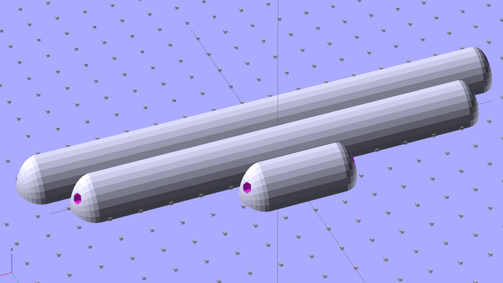
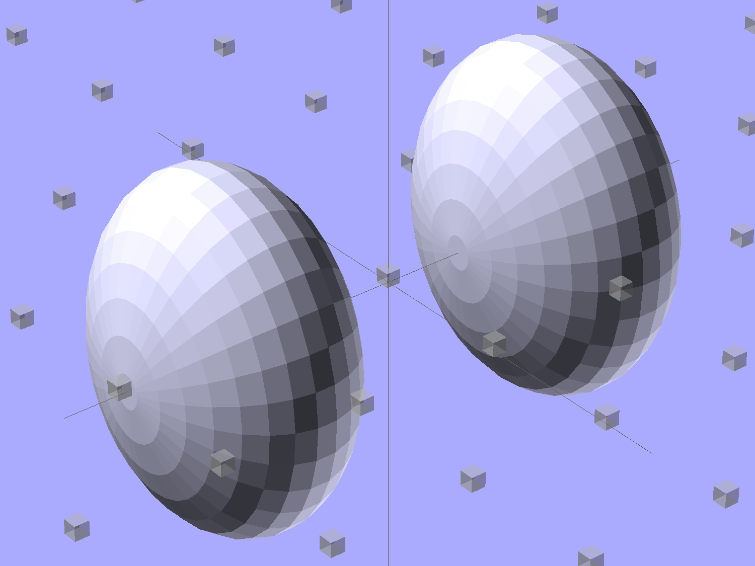
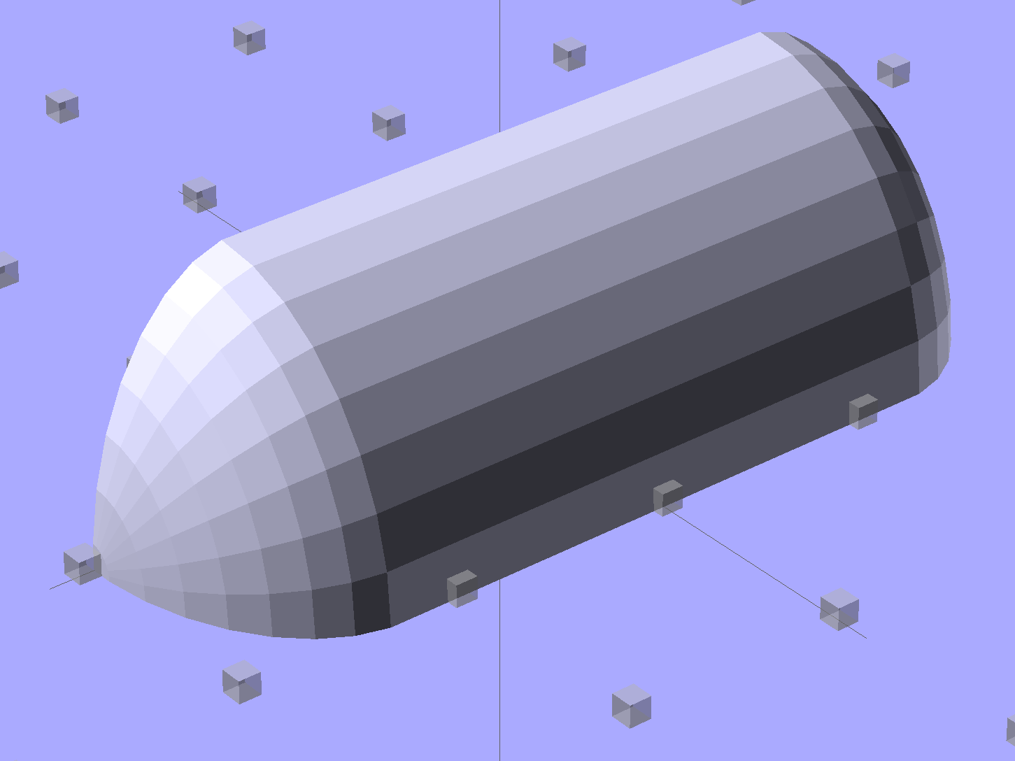
Start by placing a pair of spheroids, with radii matching the strip dimensions, so that their outer poles match the desired overall length:
Strip Light Mount – end cap spheroids – whole
The north/south poles must face outward, so that the equal-angle facets along the equators match up with what will become the mount body: rotate the spheroids 90° around the Y axis. The centers lie at the ends of the LED segments; the model shown here has a single 25 mm segment.
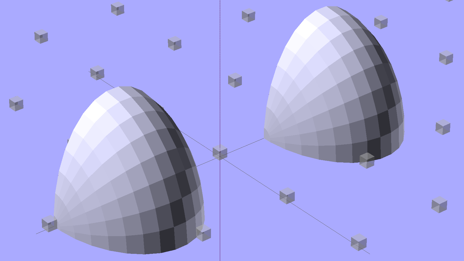
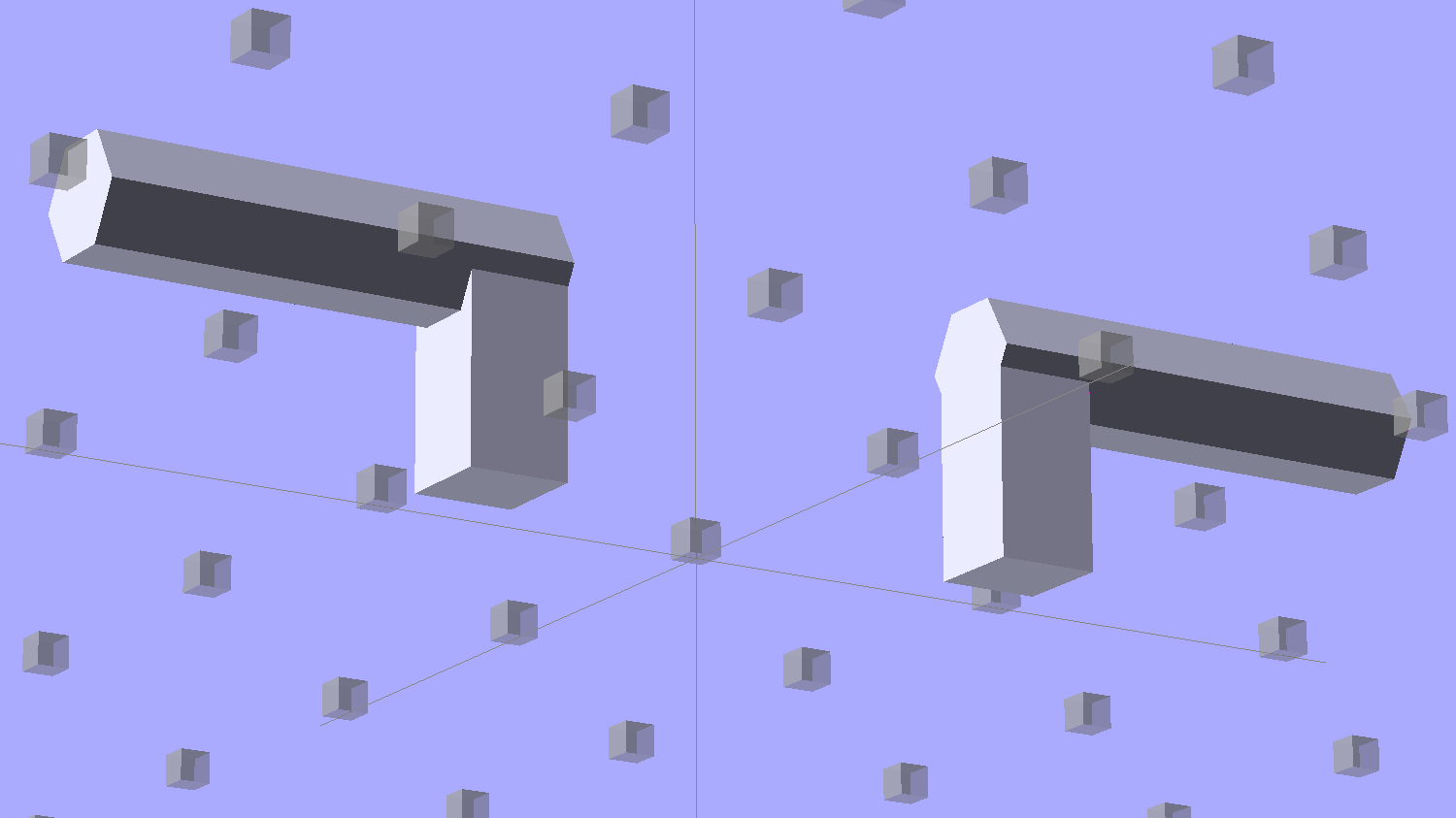
Then hack off three quadrants:
Strip Light Mount – end cap spheroids
That leaves two orange-segment shapes that define the endcaps:
Strip Light Mount – end caps – shaped
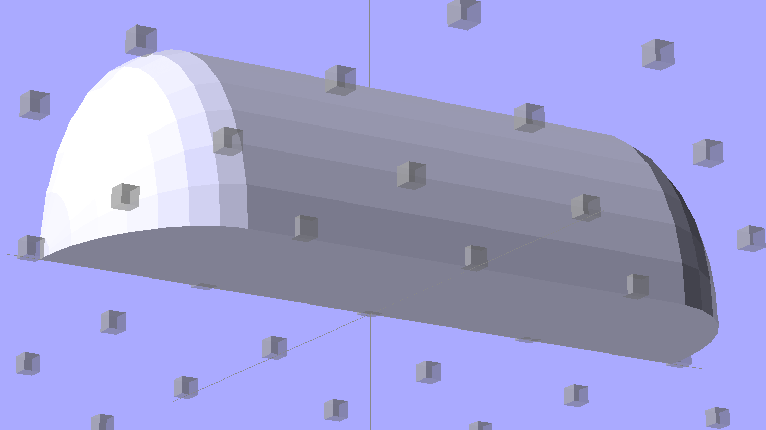
Here’s the key step that took me far too long to figure out. Shrinkwrapping the endcaps with the hull() function finesses the problem of matching the body facets to the endcap facets:
Strip Light Mount – end caps – hull
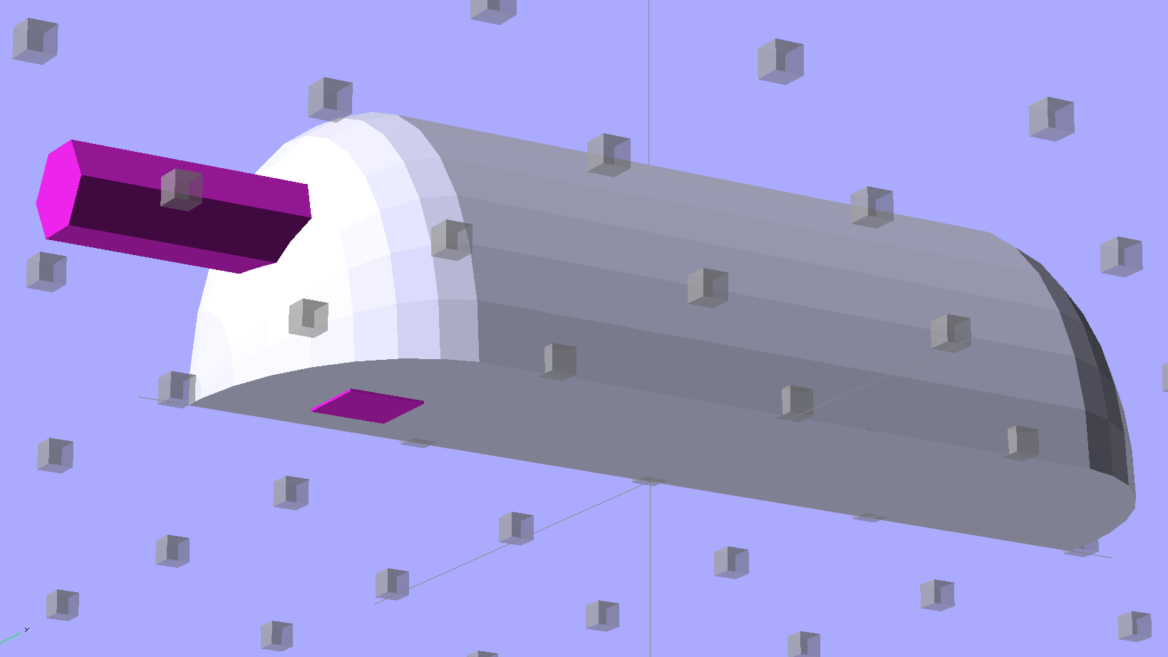
Model the wire channels as positive volumes that will be subtracted from the mount. The Channels layout shows both channels separated by a short distance:
Strip Light Mount – positive wire channels
The horizontal hexagons started as squares, but that looked hideous on the rounded endcaps.
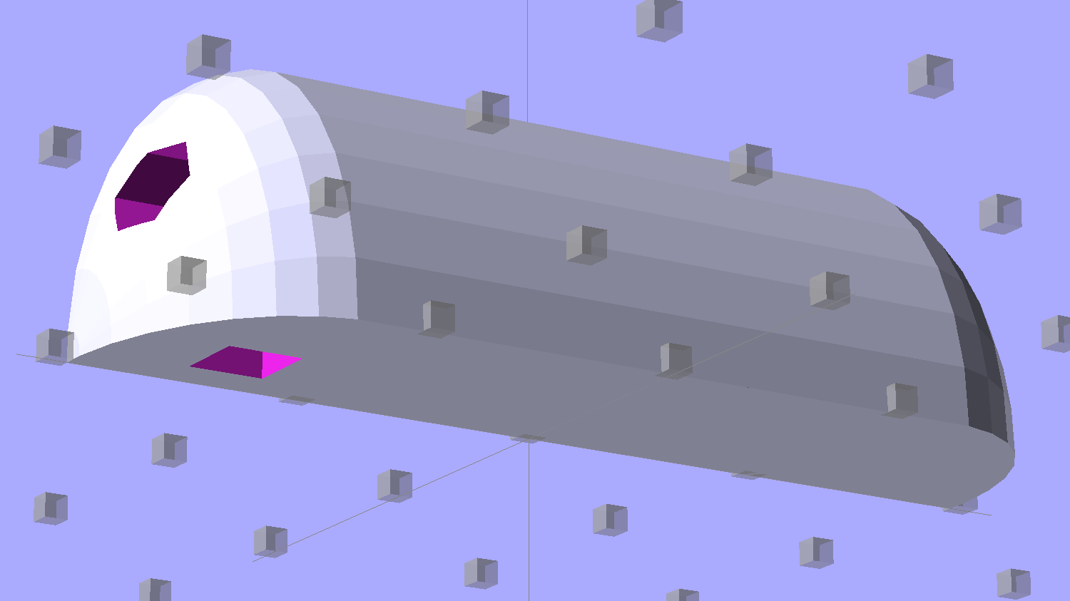
Seen from the bottom, the mount starts like this:
Strip Light Mount – no wiring channels
Position and subtract a wire channel:
Strip Light Mount – visible wire channel
Which leaves the final solid model as a single, manifold object:
Strip Light Mount – complete
The module generating the mount takes three parameters: the number of LED segments and two string variables that determine whether to punch a channel in each endcap. Instantiate the module three times with suitable parameters to get a trio of LED mounts, all laid out for 3D printing:
Strip Light Mount – build layout
They built just exactly like those models would suggest; the M2 produces dependable results.
The OpenSCAD source code:
// LED Strip Lighting Brackets for Kenmore Model 158 Sewing Machine
// Ed Nisley - KE4ZNU - February 2014

Layout = "Strip";			// Build Show Channels Strip

//- Extrusion parameters must match reality!
//  Print with 2 shells and 3 solid layers

ThreadThick = 0.20;
ThreadWidth = 0.40;

HoleWindage = 0.2;			// extra clearance

Protrusion = 0.1;			// make holes end cleanly

AlignPinOD = 1.70;			// assembly alignment pins: filament dia

inch = 25.4;

function IntegerMultiple(Size,Unit) = Unit * ceil(Size / Unit);

//----------------------
// Dimensions

Segment = [25.0,10.0,3.0];		//  size of each LED segment

WireChannel = 3.0;				// wire routing channel

StripHeight = 12.0;				// sticky tape width
StripSides = 8*4;

DefaultLayout = [1,"Wire","NoWire"];

EndCap = [(2*WireChannel + 1.0),Segment[1],StripHeight];	// radii of end cap spheroid
EndCapSides = StripSides;

CapSpace = 2.0;						// build spacing for endcaps
BuildSpace = 1.5*Segment[1];		// spacing between objects on platform

//----------------------
// Useful routines

module PolyCyl(Dia,Height,ForceSides=0) {			// based on nophead's polyholes

  Sides = (ForceSides != 0) ? ForceSides : (ceil(Dia) + 2);

  FixDia = Dia / cos(180/Sides);

  cylinder(r=(FixDia + HoleWindage)/2,
           h=Height,
           $fn=Sides);
}

module ShowPegGrid(Space = 10.0,Size = 1.0) {

  RangeX = floor(100 / Space);
  RangeY = floor(125 / Space);

	for (x=[-RangeX:RangeX])
	  for (y=[-RangeY:RangeY])
		translate([x*Space,y*Space,Size/2])
		  %cube(Size,center=true);

}

//-- The negative space used to thread wires into the endcap

module MakeWireChannel(Which = "Left") {

	HalfSpace = EndCap[0] * ((Which == "Left") ? 1 : -1);

	render(convexity=2)
	translate([0,EndCap[1]/3,0])
		intersection() {
			union() {
				cube([2*WireChannel,WireChannel,EndCap[2]],center=true);
				translate([-2*EndCap[0],0,EndCap[2]/2])
					rotate([0,90,0]) rotate(180/6)
						PolyCyl(WireChannel,4*EndCap[0],6);
			}
			translate([HalfSpace,0,(EndCap[2] - Protrusion)]) {
				cube(2*EndCap,center=true);
			}
		}
}

//-- The whole strip, minus wiring channels

module MakeStrip(Layout = DefaultLayout) {

	BarLength = Layout[0] * Segment[0];				// central bar length

	hull()
		difference() {
			for (x = [-1,1])						// endcaps as spheroids
				translate([x*BarLength/2,0,0])
					resize(2*EndCap) rotate([0,90,0]) sphere(1.0,$fn=EndCapSides);
			translate([0,0,-EndCap[2]])
				cube([2*BarLength,3*EndCap[1],2*EndCap[2]],center=true);
			translate([0,-EndCap[1],0])
				cube([2*BarLength,2*EndCap[1],3*EndCap[2]],center=true);
		}

}

//-- Cut wiring channels out of strip

module MakeMount(Layout = DefaultLayout) {

	BarLength = Layout[0] * Segment[0];

	difference() {
		MakeStrip(Layout);
		if (Layout[1] == "Wire")
			translate([BarLength/2,0,0])
				MakeWireChannel("Left");
		if (Layout[2] == "Wire")
			translate([-BarLength/2,0,0])
				MakeWireChannel("Right");
	}
}

//- Build it

ShowPegGrid();

if (Layout == "Channels") {
	translate([ EndCap[0],0,0]) MakeWireChannel("Left");
	translate([-EndCap[0],0,0]) MakeWireChannel("Right");
}

if (Layout == "Strip") {
	MakeStrip(DefaultLayout);
}

if (Layout == "Show") {
	MakeMount(DefaultLayout);
}

if (Layout == "Build") {

	translate([0,BuildSpace,0]) MakeMount([1,"Wire","Wire"]);		// rear left side, vertical
	translate([0,0,0]) MakeMount([5,"Wire","NoWire"]);				// rear top, across arm
	translate([0,-BuildSpace,0]) MakeMount([6,"NoWire","Wire"]);	// front top, across arm
}
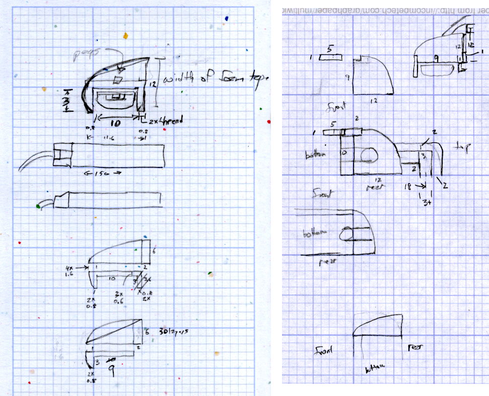
The original design doodles, which bear a vague resemblance to the final mounts:
LED Strip Light Mounts – Original Design Sketches
The little snood coming out of the top would hide a wire going through a hole drilled in the capital-S of “Sears” on the front panel, but I came to my senses long before implementing that idea…
Come to find out that Makerbot changed the spacing between the Y-axis rod and the idler bolt, so it doesn’t fit the TOM286. I could fire up the Token Windows Box, install Sketchup, modify the model, rebuild and clean up the STL, and try again, but it’s easier to just give up. The TOM286 has worked fine so far, so maybe this isn’t really needed.
After all the height map tweaking, Slic3r duplicated the Tux and SqWr STL positive models, distributed them on the platform, and the small molds printed out easily enough:
Tux SqWr positive molds – as built
The larger pin plate wasn’t quite as successful. Despite what this might look like, that’s the same black PLA as the smaller molds:
Mold peg plate – repaired
I used 10% infill density, which was structurally good enough for a very light slab, but it left large gaps near the side walls that the top fill didn’t quite cover. Part of the problem was that the walls, being cylindrical sections, kept overhanging toward the inside, leaving the top fill nothing to grab around the nearly tangential perimeter. I think printing the slab upside-down, with the top surface against the platform, would solve that problem and also produce a glass-smooth surface under the positive molds.
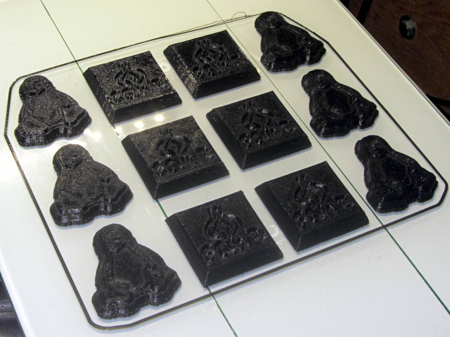
I took the easy way out by troweling JB KwikWeld epoxy into the holes, smoothing it, and sanding the surfaces more-or-less smooth. That should suffice to cast the negative mold in silicone over everything, but it sure ain’t pretty:
Mold plate with Tux SqWr positives in place
The molds are just sitting on their pegs and haven’t been taped in place; the lower-left Tux appears to be making a break for freedom.
The Mighty Thor will do the silicone negative mold… and the further I stay away from the chocolate tempering & pouring process, the better it’ll be for all parties concerned.
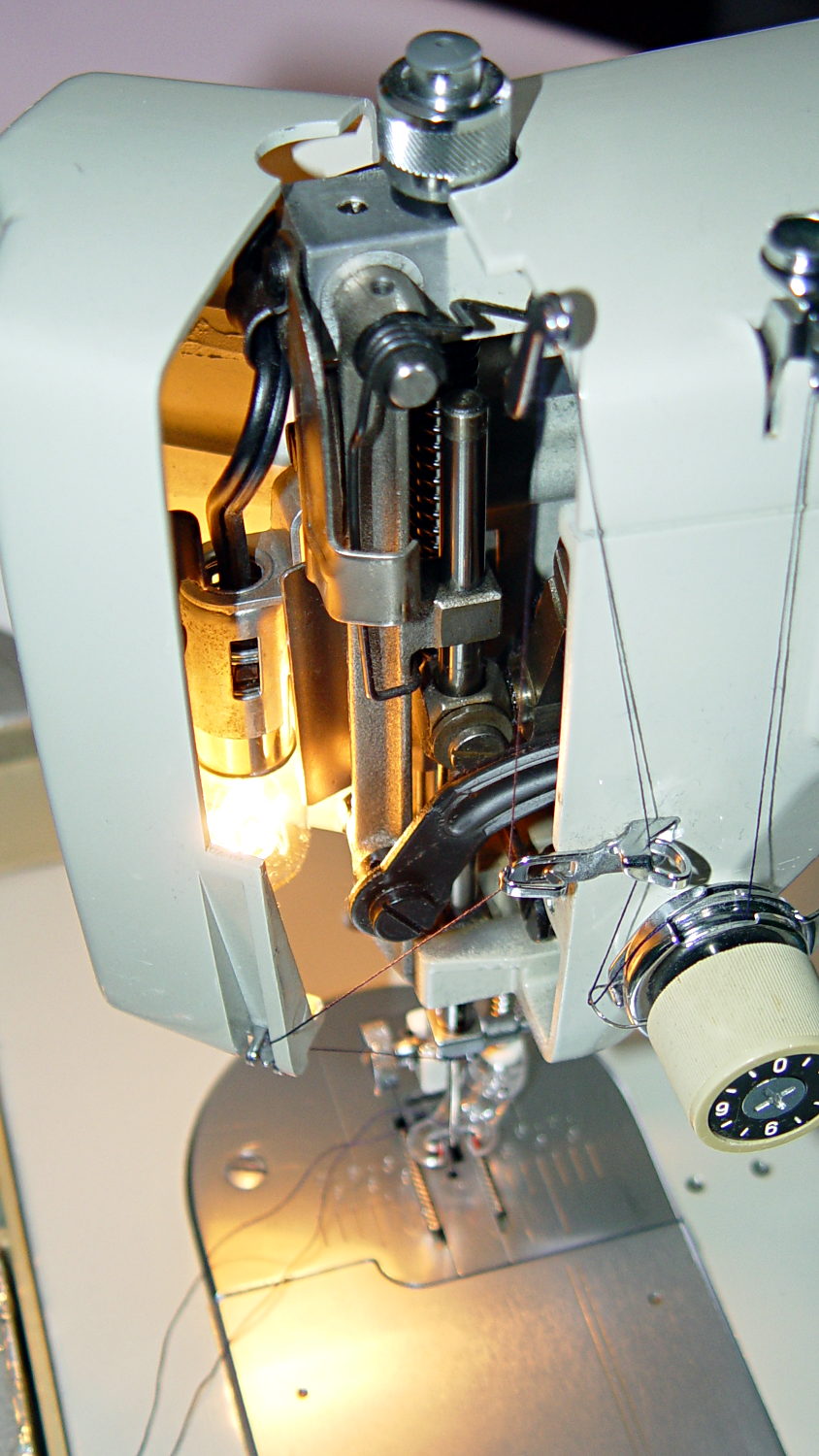
Mary wants more light directly around the needle of her Kenmore Model 158 sewing machine, as the existing light (a 120 V 15 W incandescent bulb tucked inside the end housing) casts more of a diffuse glow than a directed beam:
Kenmore Model 158 Sewing Machine – lamp
The end cap fits snugly around the bulb, but I thought a pair of 10 mm white LEDs, mounted side-by-side and aimed downward at the cover plate, would work. Of course, plugging a pair of white LEDs into a 120 VAC socket won’t work, but some judicious rewiring and a new 12 V DC wall wart will take care of that.
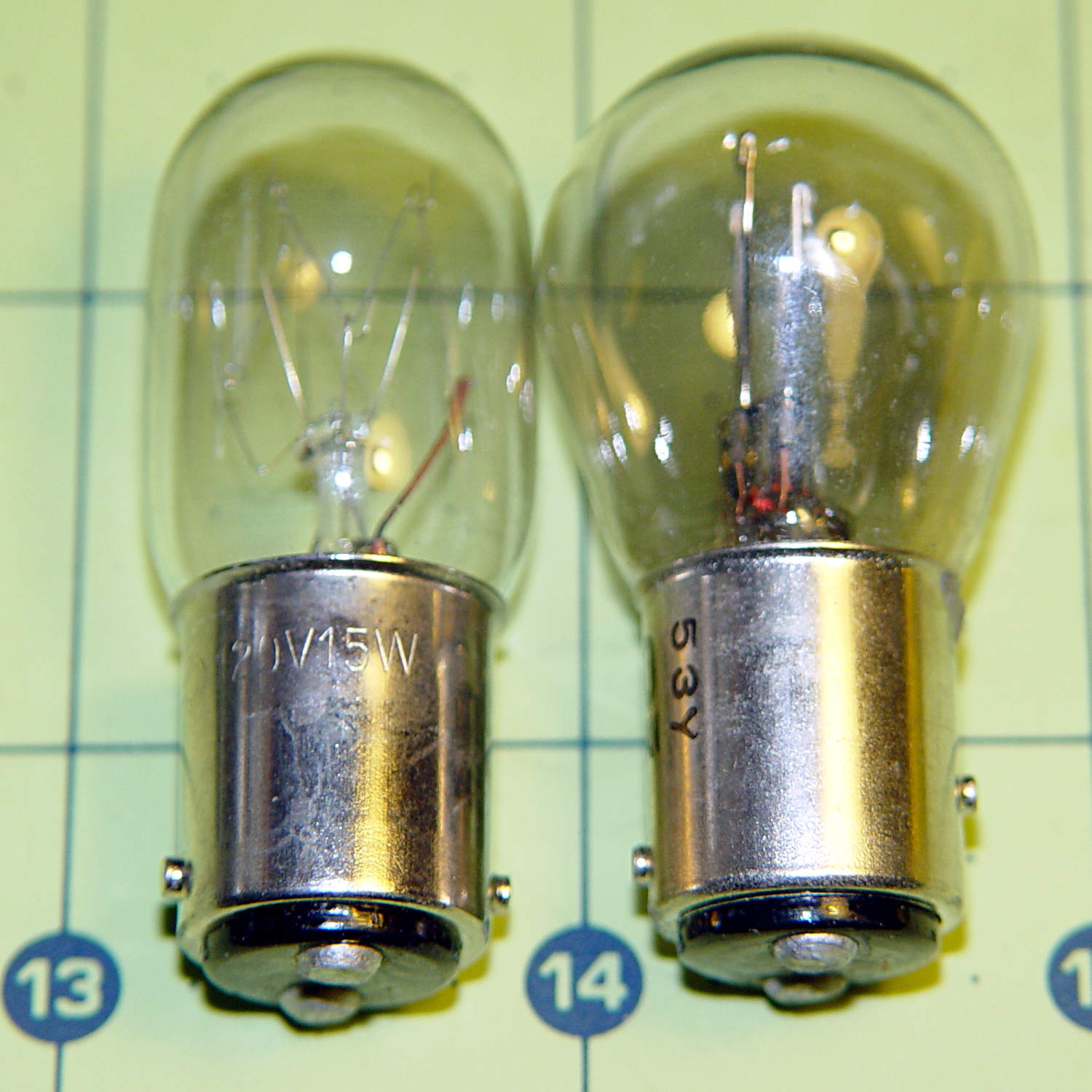
The bulb has a dual-contact bayonet base, with both pins isolated from the shell and connected to the non-polarized (!) line cord through the power switch. I didn’t know it was called a BA15d base, but now I do.
A 12 V automotive brake/taillight bulb (type 1157, I think) pulled from the Big Box o’ Bulbs has a slightly different pin arrangement that keys the filaments (which are not isolated from the shell) to the surrounding reflector:
BA15d Bayonet Bulb Bases – 120V vs. 12V pins
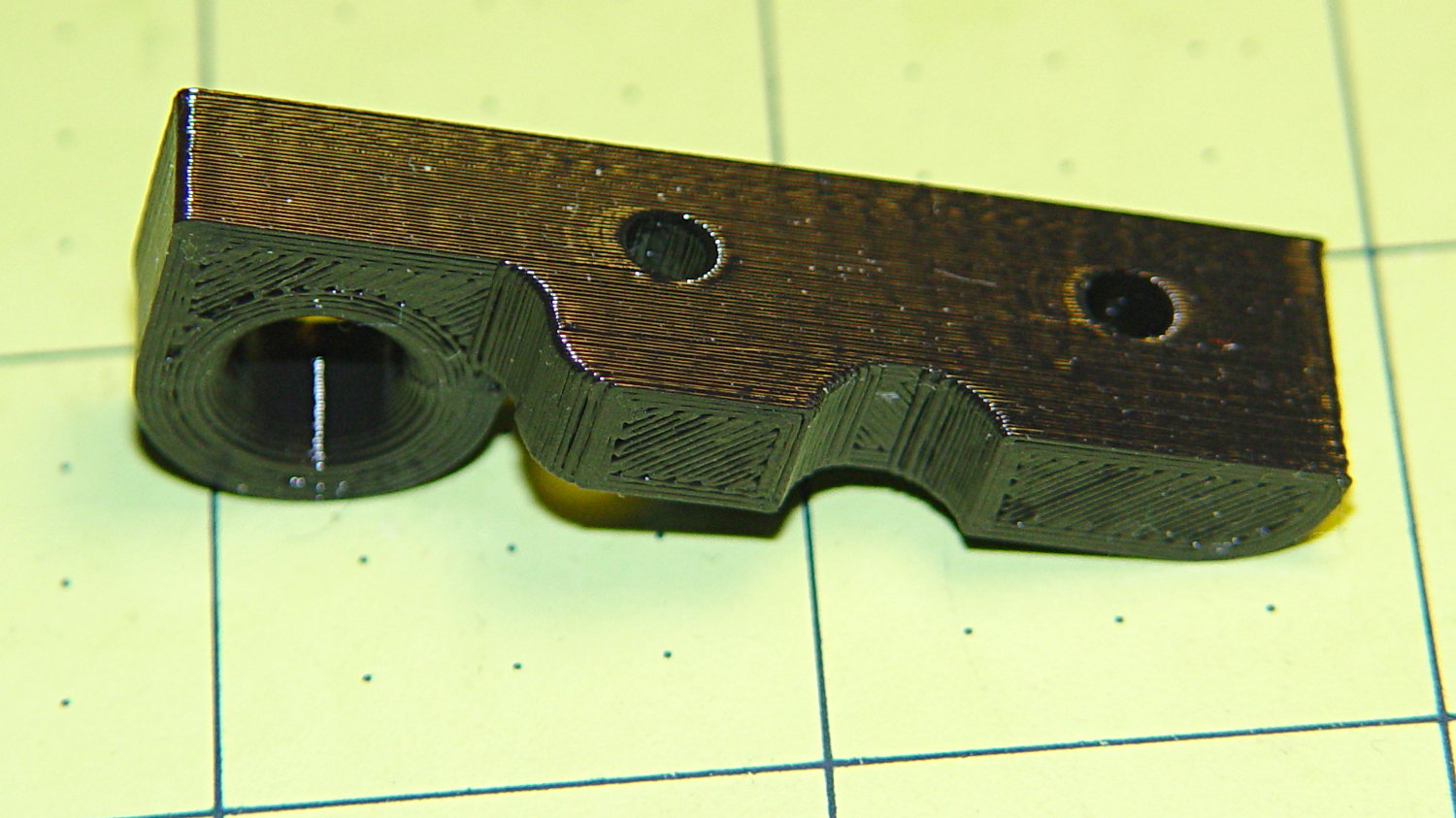
So I conjured a mockup to see if it would fit, using 2-56 screws to mimic whatever hardware might be practical:
BA15d Bulb – LED Adapter
The solid model shows how it all fits together:
Sears Lamp LED Adapter – Show view
The two tiny ruby-red pins represent filament snippets in alignment holes, barely visible in real life:
It actually fit pretty well, ignoring the fact that the LEDs point 90° from the intended direction (so I could see how the holes came out inside the pivot, honest), and lit up the area quite well, but it’s such a delicate affair that removing the entire socket and replacing it with a dedicated metal bracket / heatsink for two high-power SMD LEDs will be better.
The OpenSCAD source code:
// Adapter for LEDs in Sears sewing machine lamp socket
// Ed Nisley - KE4ZNU - January 2014

Layout = "Show";		// Build Show LEDTab LEDPlate ShellMount

//- Extrusion parameters must match reality!
//  Print with 2 shells and 3 solid layers

ThreadThick = 0.20;
ThreadWidth = 0.40;

HoleWindage = 0.2;			// extra clearance

Protrusion = 0.1;			// make holes end cleanly
Gap = 2.0;					// spacing between Show parts

AlignPinOD = 1.70;			// assembly alignment pins: filament dia

inch = 25.4;

//----------------------
// Dimensions

//-- LED mounting plate

LEDDia = 10.0;				// LED case OD
LEDFlangeOD = 10.7;

LEDPlateThick = 2.0;		// mounting plate thickness
LEDMargin = 2.0;

LEDSpaceOC = LEDDia + LEDMargin;		// LED center-to-center distance (single margin between!)

LEDTabLength = 15.0;		// base to screw hole center

LEDTabThick = 4.0;			// tab with hole for mounting screw
LEDTabScrewOD = 2.0;
LEDTabWidth = (3.0*2) + LEDTabScrewOD;

LEDMountHeight = 25.0;		// estimated mounting screw centerline to bottom of LEDs

//-- Lamp base adapter
//		hard inch dimensions!

ShellOD = 0.600 * inch;				// dia of metallic shell
ShellOAL = 0.66 * inch;				//  ... total length
ShellInsert = 7/16 * inch;			//  ... length engaging socket

ShellSides = 4*4;

BulbOD = 0.75 * inch;				// glass bulb
BulbLength = 1.14 * inch;

InsulOD = 0.485 * inch;				// insulating stub around contact pins
InsulThick = 0.070 * inch;			//  ... beyond end of shell

ContactOD = 2.0;					// contact holes through base (not heads)
ContactOC = 0.300 * inch;			//  ... center-to-center spacing

BayonetOD = 0.080 * inch;			// bayonet pin diameter
BayonetOffset = 0.125 * inch;		// from end of metal base

LampOAL = InsulThick + ShellOAL + BulbLength;
echo(str("Overall Length: ",LampOAL));

//-- Miscellany

//----------------------
// Useful routines

module PolyCyl(Dia,Height,ForceSides=0) {			// based on nophead's polyholes

  Sides = (ForceSides != 0) ? ForceSides : (ceil(Dia) + 2);

  FixDia = Dia / cos(180/Sides);

  cylinder(r=(FixDia + HoleWindage)/2,
           h=Height,
           $fn=Sides);
}

module ShowPegGrid(Space = 10.0,Size = 1.0) {

  Range = floor(50 / Space);

	for (x=[-Range:Range])
	  for (y=[-Range:Range])
		translate([x*Space,y*Space,Size/2])
		  %cube(Size,center=true);
}

//-- Tab for screw mounting LED holder
//		AddLength remains below Z=0 for good union

module LEDTab() {

	difference() {
		linear_extrude(height=LEDTabThick)
			hull() {
				circle(d=LEDTabWidth);
				translate([LEDTabLength/2,0,0])
					square([LEDTabLength,LEDTabWidth],center=true);
			}
		translate([0,0,-Protrusion])
			rotate(180/6)
				PolyCyl(LEDTabScrewOD,(LEDTabThick + 2*Protrusion),6);
		for (i=[-1,1])
			translate([LEDTabLength/2,i*LEDTabWidth/4,LEDTabThick/2])
				rotate([0,90,0]) rotate(180/4)
					PolyCyl(AlignPinOD,(LEDTabLength/2 + Protrusion),4);
	}
}

//-- Plate holding LEDs

module LEDPlate() {

	difference() {
		union() {
			linear_extrude(height=LEDPlateThick)
				hull() {
					for (i=[-1,1])
						translate([i*LEDSpaceOC/2,0,0])
							circle(d=(LEDDia + 2*LEDMargin));
					translate([0,(LEDFlangeOD/2 + LEDTabWidth/2),0])
						square([LEDTabThick,LEDTabWidth],center=true);
				}
		}
		for (i=[-1,1])
			translate([i*LEDSpaceOC/2,0,-Protrusion])
				rotate(180/12)
					PolyCyl(LEDDia,(LEDPlateThick + 2*Protrusion),12);
		for (i=[-1,1])
			translate([0,(i*LEDTabWidth/4 + LEDFlangeOD/2 + LEDTabWidth/2),3*ThreadThick]) rotate(180/4)
				PolyCyl(AlignPinOD,(LEDTabLength/2 + Protrusion),4);

	}
}

//-- Bulb shell mounting adapter

module ShellMount() {

	difference() {
		union() {
			cylinder(r1=InsulOD/2,r2=ShellOD/2,h=(InsulThick + Protrusion),$fn=ShellSides);
			translate([0,0,InsulThick])
				cylinder(r=ShellOD/2,h=(LampOAL - LEDMountHeight + LEDTabWidth/2),$fn=ShellSides);
		}

		translate([0,ShellOD,(InsulThick + BayonetOffset)])		// bayonet pin hole
			rotate([90,0,0]) rotate(180/4)
				PolyCyl(BayonetOD,2*ShellOD,4);

		translate([0,ShellOD,(InsulThick + LampOAL - LEDMountHeight)])		// LED mount screw hole
			rotate([90,0,0])
				PolyCyl(LEDTabScrewOD,2*BulbOD,6);

		translate([0,0,(InsulThick + ShellOAL + LampOAL/2)])		// slot for LEDTab mount
			cube([2*ShellOD,(LEDTabThick + 2*Protrusion),LampOAL],center=true);

		for (i=[-1,1])											// contact pin holes
			translate([i*ContactOC/2,0,-Protrusion])
				rotate(180/6)
					PolyCyl(ContactOD,2*LampOAL,6);
	}

}

//- Build it

ShowPegGrid();

if (Layout == "LEDTab")
	LEDTab();

if (Layout == "LEDPlate")
	LEDPlate();

if (Layout == "ShellMount")
	ShellMount();

if (Layout == "Show") {
	LEDPlate();
	translate([-LEDTabThick/2,(LEDFlangeOD/2 + LEDTabWidth/2),(LEDTabLength + LEDPlateThick + Gap)])
		rotate([0,90,0])
			LEDTab();
	for (i=[-1,1])
#	translate([0,(i*LEDTabWidth/4 + LEDFlangeOD/2 + LEDTabWidth/2),(LEDPlateThick + Gap/4)])
		rotate(180/4)
		cylinder(r=AlignPinOD/2,h=Gap/1,$fn=4);		// fake the pins

	translate([0,(LEDFlangeOD/2 + LEDTabWidth/2),(LampOAL - LEDTabWidth/2)])
		rotate([0,180,0]) rotate(90)
			ShellMount();
}

if (Layout == "Build") {
	translate([0,LEDDia,0])
		LEDPlate();

	translate([-10,-(LEDMargin + LEDTabWidth),0])
		rotate(-90)
			LEDTab();

	translate([10,-(LEDMargin + LEDTabWidth),0])
		ShellMount();
}
The original doodles for the bulb dimensions and adapter layout: