Ed Nisley's Blog: Shop notes, electronics, firmware, machinery, 3D printing, laser cuttery, and curiosities. Contents: 100% human thinking, 0% AI slop.
Under ordinary circumstances, a fuseholder mounts in a square-ish panel cutout, but there’s no convenient panel to be found in the repurposed GX270 case. So now there’s a holder for the fuseholder stuck to the side of the power supply inside the case:
Fuseholder – installed
The square tube covers the entire fuseholder, with the quick-connect tabs protruding from the back, to provide enough surface area for the double-stick foam tape.
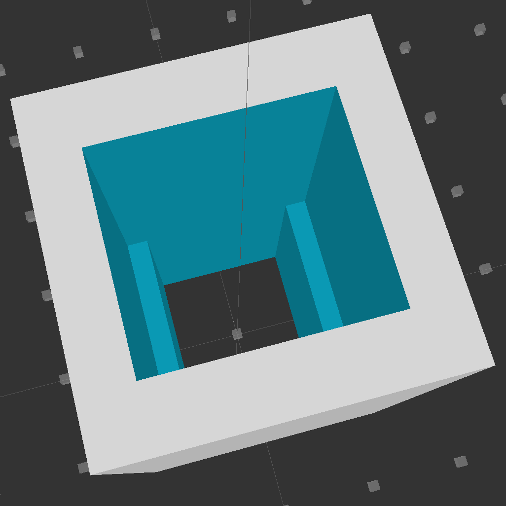
Looking down into the solid model, you can see the reduced width near the back end:
Fuseholder Holder
The black fuseholder contains a 5 A fast blow fuse, which should be entirely adequate for normal operation. In the event that a wire breaks loose and contacts the metal shell surrounding the whole chassis, it will pop instantly. That won’t disable the power supply, but it will remove line voltage from the entire motor controller chassis.
Remember that the source power line goes to the center QC tab, thus burying the always-hot contact deep in the fuseholder.
The OpenSCAD source code:
// Fuseholder mount
// Ed Nisley - KE4ZNU - August 2014

//- Extrusion parameters must match reality!

ThreadThick = 0.20;
ThreadWidth = 0.40;

HoleWindage = 0.2;			// extra clearance

Protrusion = 0.1;			// make holes end cleanly

AlignPinOD = 1.70;			// assembly alignment pins: filament dia

function IntegerMultiple(Size,Unit) = Unit * ceil(Size / Unit);

//----------------------
// Dimensions

Shell = [25.0,25];						// outside = bezel size + some stiffening

Mount = [17.3,15.7,21.0];					// mount section = slight compression in X
Base = [13.5,15.7,17.0];					// clearance over crimped contact

OAL = Mount[2] + Base[2];

//----------------------
// Useful routines

module PolyCyl(Dia,Height,ForceSides=0) {			// based on nophead's polyholes

  Sides = (ForceSides != 0) ? ForceSides : (ceil(Dia) + 2);

  FixDia = Dia / cos(180/Sides);

  cylinder(r=(FixDia + HoleWindage)/2,
           h=Height,
           $fn=Sides);
}

module ShowPegGrid(Space = 10.0,Size = 1.0) {

  RangeX = floor(100 / Space);
  RangeY = floor(125 / Space);

	for (x=[-RangeX:RangeX])
	  for (y=[-RangeY:RangeY])
		translate([x*Space,y*Space,Size/2])
		  %cube(Size,center=true);

}

//----------------------
// Build it

ShowPegGrid();

difference() {
	translate([0,0,OAL/2])
		cube([Shell[0],Shell[1],OAL],center=true);
	translate([0,0,Base[2] + Mount[2]/2])
		cube(Mount + [0,0,2*Protrusion],center=true);
	translate([0,0,Base[2]/2])
		cube(Base + [0,0,2*Protrusion],center=true);
}
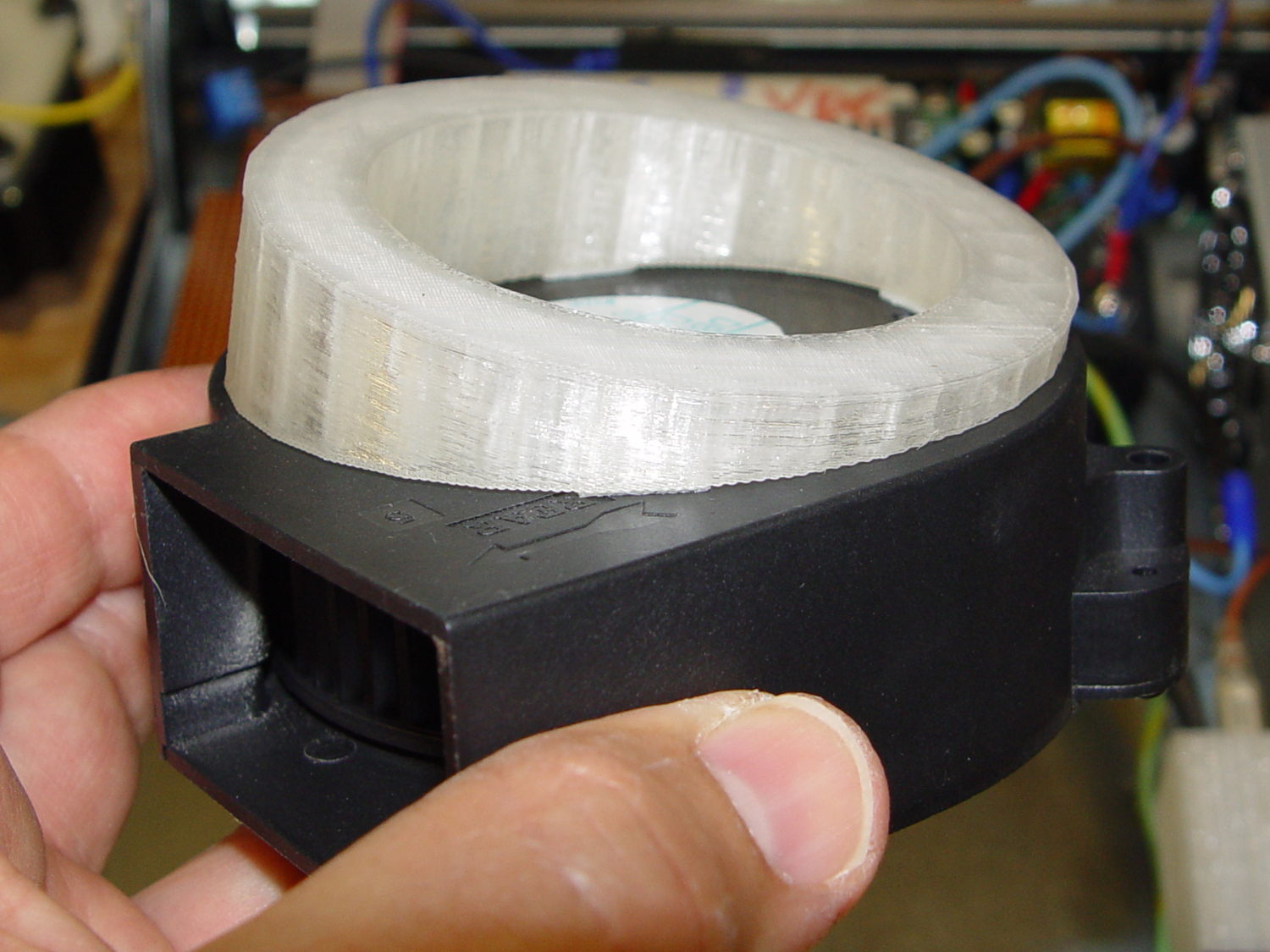
This angled ring fits under a repurposed CPU cooler:
Blower Mount – solid model
Viewed perpendicular to the angled surface, it’s a circle, so what looks like a vertical cylinder is actually slightly oval to make the top come out right. That way, the walls are vertical, not angled, and it doesn’t stand crooked on the base plate.
Such a shape is trivially easy for a 3D printer:
Blower mount – on build platform
And looks about like you’d expect on the blower, which is why that surface must be a circle:
Blower Mount – bottom view
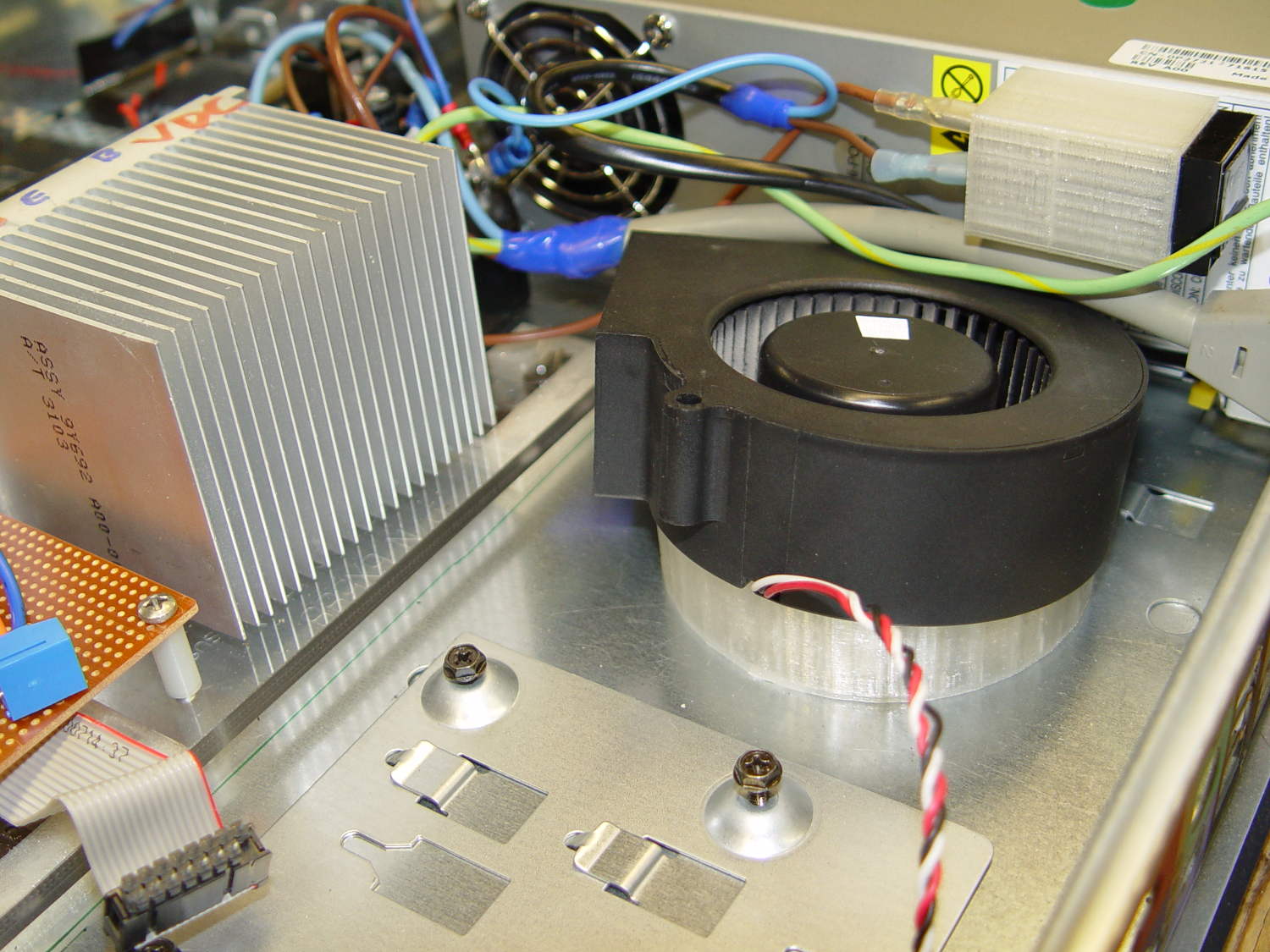
A trial fit in the case, along with a bunch of parts I haven’t written up yet:
Blower Mount – installed
Under normal circumstances, you’d want the blower a bit higher and level, but there just wasn’t anywhere else to fit the fuseholder. Besides, this way the airflow goes slightly upward toward the clearance over the top of that monster heatsink. Some air flows along the side of the heatsink to cool the isolated power supply you can’t quite see in the far corner of the chassis beyond that tangle of wires.
The angle seems pretty close to right, although I must get the rest of the circuitry running to know if the airflow can actually transfer the heat from the heatsink out of the case.
It doesn’t take much OpenSCAD source code to define the shape:
// Blower mount
// Ed Nisley - KE4ZNU - August 2014

//- Extrusion parameters must match reality!

ThreadThick = 0.20;
ThreadWidth = 0.40;

HoleWindage = 0.2;			// extra clearance

Protrusion = 0.1;			// make holes end cleanly

AlignPinOD = 1.70;			// assembly alignment pins: filament dia

function IntegerMultiple(Size,Unit) = Unit * ceil(Size / Unit);

//----------------------
// Dimensions

MountOD = 85.0;						// a bit smaller than the housing OD

MountID = 60.0;						// carve out to reduce printing time

Base = 5.0;							// minimum thickness (allowing for some overhang)

ElevationAngle = atan(20/90);		// net tilt across fan base

ElevationDelta = MountOD * tan(ElevationAngle);

echo(str("Elevation angle: ",ElevationAngle," delta: ",ElevationDelta));

//----------------------
// Useful routines

module PolyCyl(Dia,Height,ForceSides=0) {			// based on nophead's polyholes

  Sides = (ForceSides != 0) ? ForceSides : (ceil(Dia) + 2);

  FixDia = Dia / cos(180/Sides);

  cylinder(r=(FixDia + HoleWindage)/2,
           h=Height,
           $fn=Sides);
}

module ShowPegGrid(Space = 10.0,Size = 1.0) {

  RangeX = floor(100 / Space);
  RangeY = floor(125 / Space);

	for (x=[-RangeX:RangeX])
	  for (y=[-RangeY:RangeY])
		translate([x*Space,y*Space,Size/2])
		  %cube(Size,center=true);

}

//----------------------
// Build it

ShowPegGrid();

difference() {
	scale([1,cos(ElevationAngle),1])
		cylinder(d=MountOD,h=Base + ElevationDelta);
	translate([-MountOD,-MountOD/2,Base])
		rotate([ElevationAngle,0,0])
			cube([2*MountOD,2*MountOD,ElevationDelta],center=false);
	translate([0,0,-Protrusion])
		cylinder(d=MountID,h=Base + 3*ElevationDelta);
}
Given the fragility of ferrite toroids in general and slit toroids in particular, a touch of up-armoring seems sensible:
FT82-43 toroid – mounted
The solid model includes a toroid shell with roughly the right curves:
Toroid Mount – Show layout
That puts a nice rounded shape on the bottom of the armor, not that that makes much difference:
Toroid Mount – Build layout
The central hole passes a 4-40 brass, nylon, or stainless steel screw. Most of the magnetic field stays within the ferrite and, heck, this isn’t a crazy-sensitive analog application, so even an ordinary steel screw shouldn’t cause any particular problems.
The rectangular (not pie-wedge) slit barely passes the Hall effect sensor.
I’ll pour some clear epoxy over the toroid, with tape masking the ferrite core and sealing the ends, to immobilize the windings. That sounds like a good idea after calibration and suchlike.
The OpenSCAD source code, which should be sufficiently parametric that I can crank ’em out for all the other toroids large enough to accept a screw:
// Toroid coil mounting bracket
// Ed Nisley - KE4ZNU - August 2014

Layout = "Mount";			// Coil Mount Build Show

//- Extrusion parameters must match reality!
//  Print with 4 shells and 3 solid layers

ThreadThick = 0.20;
ThreadWidth = 0.40;

HoleWindage = 0.2;			// extra clearance

Protrusion = 0.1;			// make holes end cleanly

AlignPinOD = 1.70;			// assembly alignment pins: filament dia

function IntegerMultiple(Size,Unit) = Unit * ceil(Size / Unit);

//----------------------
// Dimensions

ID = 0;												// subscripts for cylindrical objects
OD = 1;
LEN = 2;

Coil = [10.25,23.50,8.3];							// wound toroid core

SensorThick = 2.0;

BaseThick = IntegerMultiple(1.0,ThreadThick);		// baseplate under coil
WallThick = IntegerMultiple(1.0,ThreadWidth);		// walls beside coil

ScrewHoleDia = 4.0;									// allow alignment slop around 3 mm / #4 screws

//----------------------
// Useful routines

module PolyCyl(Dia,Height,ForceSides=0) {			// based on nophead's polyholes

  Sides = (ForceSides != 0) ? ForceSides : (ceil(Dia) + 2);

  FixDia = Dia / cos(180/Sides);

  cylinder(r=(FixDia + HoleWindage)/2,
           h=Height,
           $fn=Sides);
}

module ShowPegGrid(Space = 10.0,Size = 1.0) {

  RangeX = floor(100 / Space);
  RangeY = floor(125 / Space);

	for (x=[-RangeX:RangeX])
	  for (y=[-RangeY:RangeY])
		translate([x*Space,y*Space,Size/2])
		  %cube(Size,center=true);

}

//----------------------
// Basic coil shape

module CoilShape() {

CornerRadius = min((Coil[LEN] / 2),((Coil[OD] - Coil[ID]) / 2))  / 3;
MidRadius = (Coil[ID] + Coil[OD]) / 4;
HalfX = (Coil[OD] - Coil[ID]) / 4 - CornerRadius;
HalfY = (Coil[LEN] / 2) - CornerRadius;

echo(CornerRadius,MidRadius,HalfX,HalfY);

	color("Goldenrod")
	render(convexity = 2)
		rotate(180/20)
			rotate_extrude(convexity=3,$fn=20)
				translate([MidRadius,0])
					hull()
						for (i=[-1,1],j=[-1,1])
							translate([i*HalfX,j*HalfY])
								circle(r=CornerRadius,$fn=24);
}

//----------------------
// Mount

module Mount() {

	difference() {
		rotate(180/20)
			cylinder(h=(BaseThick + Coil[LEN]),d=(Coil[OD] + 2*WallThick),$fn=20);

		translate([0,0,-Coil[LEN]])							// make screw hole
			rotate(180/6)
				PolyCyl(ScrewHoleDia,3*Coil[LEN],$fn=6);

		translate([0,0,BaseThick + Coil[LEN]/2])			// set bottom curve
			CoilShape();

		translate([0,0,BaseThick + Coil[LEN]])				// clear out top
			CoilShape();

		translate([(Coil[ID]/2 + Coil[OD]/2),0,0])
			cube([Coil[OD],SensorThick,3*Coil[LEN]],center=true);
	}
}


ShowPegGrid();

if (Layout == "Coil") {
	CoilShape();
}

if (Layout == "Mount")
	Mount();

if (Layout == "Show") {
	Mount();
	translate([0,0,(BaseThick + Coil[LEN]/2)])
		CoilShape();
}


if (Layout == "Build") {
	Mount();
}
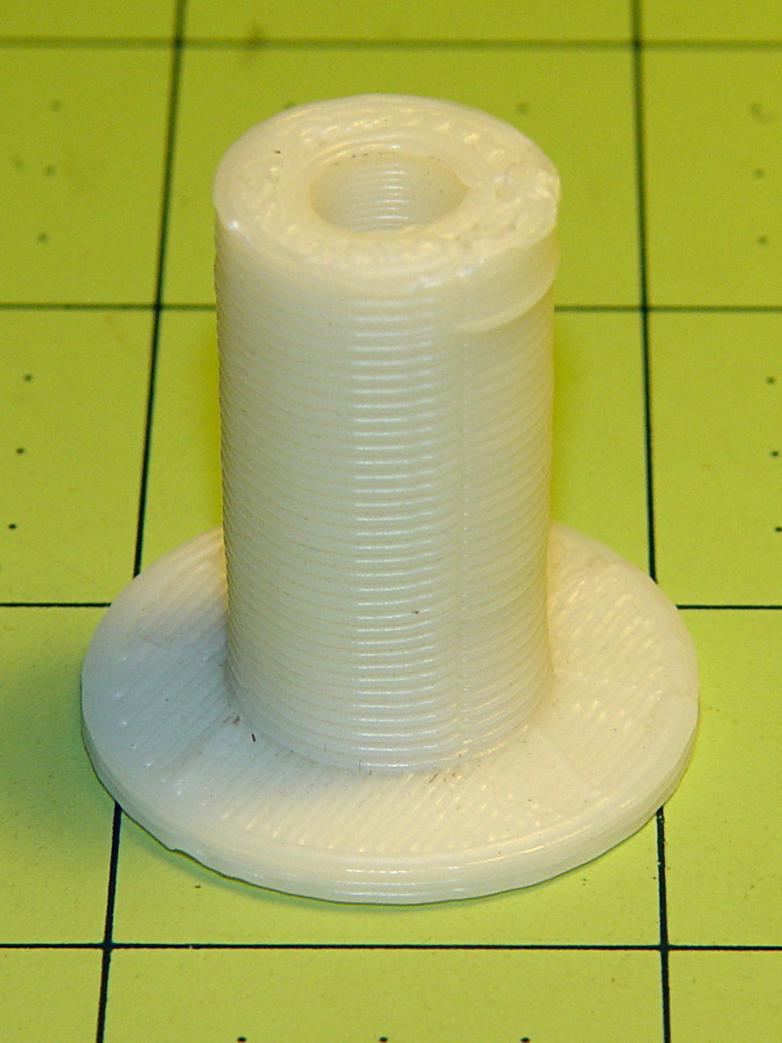
Mary recently learned that large spools of thread have a cross-wound lay that should feed over the end, not from the side as do ordinary stack-wound spools. So I built a right-angle adapter that fits over the not-quite-vertical spool pin on the sewing machine and aims directly at the thread tensioner:
Large spool adapter – on sewing machine
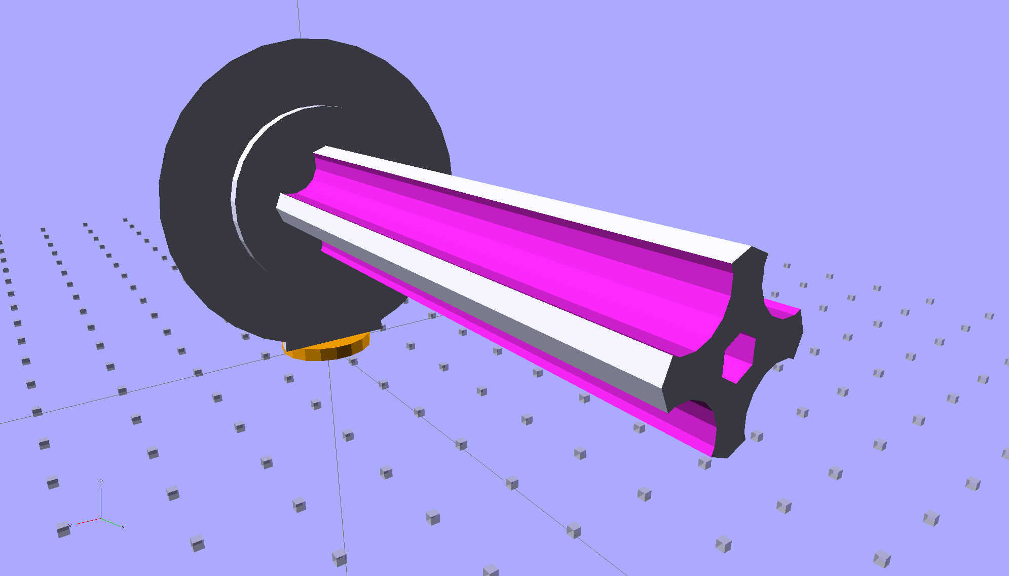
The solid model shows off the fluted rod that passes through the spool:
Large Spool Adapter – solid model – mount
It’s more impressive from the other end:
Large Spool Adapter – solid model – spool end
The first pass at the rod had six flutes, but that seemed unreasonably fine; now it has four. The round base on the rod provides more griptivity to the platform while building and has enough space for the two alignment pins that position it in the middle of the dome:
Large Spool Adapter – solid model – alignment holes
The dome gets glued to the rod base plate:
Large spool adapter – clamped
The spool pin hole is a snug fit around the pin on the sewing machine, because otherwise it would tend to rotate until the spool pointed to the rear of the machine. The fluted rod is a snug friction fit inside the (cardboard) spool. Some useful dimensions:
Spool pin (on Model 158): 5 mm OD, 40 mm tall
Large spool cores: 16 mm ID, 27 mm OD, 70 mm long
I had all manner of elaborate plans to make an expanding fluted rod, but came to my senses and built the simple version first. If that rod isn’t quite big enough, I can build another adapter, just like this one, only slightly larger. The source code includes a 0.5 mm taper, which may suffice.
Back in the day, shortly after the Thing-O-Matic started producing dependable results, one of the very first things I made was a simple adapter to mount large spools on the pin in the most obvious way:
Large spool adapter – old TOM version
Now we all know better than that, my OpenSCAD-fu has grown stronger, and the M2 produces precise results. Life is good!
The OpenSCAD source code:
// Large thread spool adapter
// Ed Nisley - KE4ZNU - August 2014

Layout = "Show";			// Build Show Spindle Spool

Gap = 10.0;					// between pieces in Show

//- Extrusion parameters must match reality!
//  Print with 4 shells and 3 solid layers

ThreadThick = 0.20;
ThreadWidth = 0.40;

HoleWindage = 0.2;			// extra clearance

Protrusion = 0.1;			// make holes end cleanly

AlignPinOD = 1.70;			// assembly alignment pins: filament dia

function IntegerMultiple(Size,Unit) = Unit * ceil(Size / Unit);

//----------------------
// Dimensions

LEN = 0;											// subscripts for cylindrical objects
ID = 1;
OD = 2;

Spindle = [40.0,5.0,14.0];							// spool spindle on sewing machine
Spool = [70.0,16.0,27.0];							// spool core

Taper = 0.50;										// spool diameter increase at base

CottonRoll = [65.0,Spool[OD],45.0];					// thread on spool

Mount = [Spindle[LEN],(Spindle[ID] + 4*ThreadWidth),1.0*Spool[ID]];

Flutes = 4;
Flange = [2.0,Spool[OD],Spool[OD]];

ScrewHole = [10.0,4.0 - 0.7,5.0];					// retaining screw

PinOC = Spool[ID]/4;								// alignment pin spacing

//----------------------
// Useful routines

module PolyCyl(Dia,Height,ForceSides=0) {			// based on nophead's polyholes

  Sides = (ForceSides != 0) ? ForceSides : (ceil(Dia) + 2);

  FixDia = Dia / cos(180/Sides);

  cylinder(r=(FixDia + HoleWindage)/2,
           h=Height,
           $fn=Sides);
}

module ShowPegGrid(Space = 10.0,Size = 1.0) {

  RangeX = floor(100 / Space);
  RangeY = floor(125 / Space);

	for (x=[-RangeX:RangeX])
	  for (y=[-RangeY:RangeY])
		translate([x*Space,y*Space,Size/2])
		  %cube(Size,center=true);

}

//- Locating pin hole with glue recess
//  Default length is two pin diameters on each side of the split

module LocatingPin(Dia=AlignPinOD,Len=0.0) {

	PinLen = (Len != 0.0) ? Len : (4*Dia);

	translate([0,0,-ThreadThick])
		PolyCyl((Dia + 2*ThreadWidth),2*ThreadThick,4);

	translate([0,0,-2*ThreadThick])
		PolyCyl((Dia + 1*ThreadWidth),4*ThreadThick,4);

	translate([0,0,-(Len/2 + ThreadThick)])
		PolyCyl(Dia,(Len + 2*ThreadThick),4);

}

//----------------------
// Spindle

module SpindleMount() {

	render(convexity=4)
	difference() {
		union() {
			resize([0,0,Mount[OD]])							// spool backing plate
				translate([0,CottonRoll[OD]/2,0])
					sphere(d=CottonRoll[OD],center=true);
			translate([0,CottonRoll[OD]/4,0])				// mounting post
				rotate([90,0,0])
					cylinder(d=Mount[OD],h=CottonRoll[OD]/2,center=true);
		}

		translate([0,(2*Mount[LEN] - Protrusion),Mount[OD]/4])				// punch spindle hole
			rotate([90,0,0])
//				PolyCyl(Spindle[ID],2*Mount[LEN],6);
				cylinder(d=Spindle[ID],h=2*Mount[LEN],$fn=6);

		for (i=[-1,1]) {									// punch alignment pin holes
			translate([i*PinOC,CottonRoll[OD]/2,0])
					LocatingPin(Len=Mount[OD]/3);
		}

		translate([0,0,-CottonRoll[OD]])					// remove half toward spool
			cube(2*CottonRoll[OD],center=true);
	}

}

//----------------------
// Spool holder

module SpoolMount() {

	difference() {

		union() {

			translate([0,0,(Flange[LEN] - Protrusion)])
				difference() {
					cylinder(d1=(Spool[ID] + Taper),d2=Spool[ID],h=Spool[LEN],$fn=2*Flutes);						// fit spool ID

					for (a=[0 : 360/Flutes : 360-1])						// create flutes
						rotate(a + 180/Flutes)
							translate([Spool[ID]/2,0,-Protrusion])
								rotate(180/16)
								cylinder(r=Spool[ID]/4,h=(Spool[LEN] + 2*Protrusion),$fn=16);

					translate([0,0,(Spool[LEN] - ScrewHole[LEN])])			// punch screw hole
						PolyCyl(ScrewHole[ID],(ScrewHole[LEN] + Protrusion),6);

				}
			cylinder(d=Flange[OD],h=Flange[LEN]);							// base flange
		}

		for (i=[-1,1])												// punch alignment pin holes
			translate([0,i*PinOC,0])								//  ... orients solid flange up
					LocatingPin(Len=Flange[LEN]);
	}

}


ShowPegGrid();

if (Layout == "Spindle") {
	SpindleMount();
}
if (Layout == "Spool") {
	SpoolMount();
}

if (Layout == "Show") {
	translate([0,Mount[OD]/4,2.0]) {
		rotate([90,0,0])
			SpindleMount();
		translate([0,Gap,CottonRoll[OD]/2])
			rotate([-90,0,0]) rotate(90)
				SpoolMount();
	}
	color("Orange") {
		translate([0,0,2])
			cylinder(d=Spindle[ID],h=Spindle[LEN],$fn=6);
		cylinder(d=Spindle[OD],h=2.0,$fn=18);
	}

}

if (Layout == "Build") {
	translate([-5,0,0])
		rotate(90)
			SpindleMount();
	translate([Flange[OD]/2,0,0])
			SpoolMount();
}
A friend had his Makergear M2 filament drive motor stop driving the filament; the problem turned out to be a severely worn pinion gear on the motor shaft. Perhaps Makergear got a pallet of bad motors, as the problem seems to affect a batch of printers made during the middle of 2013, more or less.
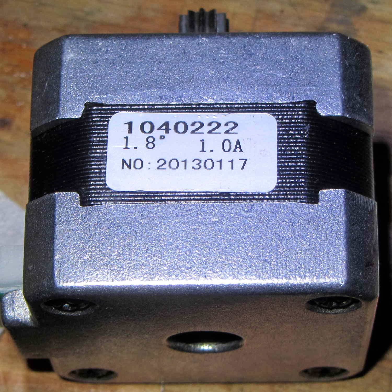
The motor on my printer came off the line in early 2013, if that’s really a date code:
M2 Extruder motor – data sticker
There’s no manufacturer, but the 104022 number matches up with a Kysan motor. The description doesn’t say anything about the interior of the gearbox, but that’s not surprising. The gear ratio is 5.2:1, not the 5:1 I’d been assuming, which gets compensated out later on.
The pinion gear is worn, but not severely, and the three planet gears are in fine shape:
M2 Extruder – planetary gears
Slather everything with lithium gear grease, stuff the parts back in place, and it’s all good.
The socket-head set screws may have a bit of threadlock, as they’re firmly set in place, and, as you’d expect, Harbor Freight hex wrenches are made of butter-soft steel that’s totally useless in sizes below about 2.5 mm. In fact, those screws rounded the end of an old Craftsman wrench, so maybe they’re slightly oversize.
This doesn’t happen very often, but, after a few road trips and some jostling around, the M2’s platform was definitely out of alignment: the first layer came out generally too thin, with the X-Y+ quadrant very much too thin.
I tried a quick and dirty adjustment that didn’t produce meaningful results, then broke out the Starrett Taper Gauge and did it right.
Jog around measuring the height of the nozzle above the platform
Adjust screws to reduce variation
Change Z offset in startup G-Code
Run off a few test patterns to get the platform heated
Measure actual thickness
Change Z offset to get the right answer
Done!
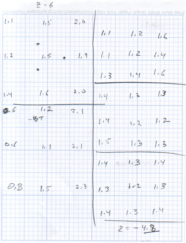
This progression of cold measurements, read top-to-bottom, left column first, shows the observed nozzle height above the platform around the edges and at the center:
M2 Platform Leveling Progression – 2014-06-30
The final measurements seem to indicate the glass plate is 0.2 mm convex in the center, but I wouldn’t trust the measurements to that level of accuracy. It’s probably bowed upward, but it’s certainly close enough.
The cold measurements suggest that the Z offset should be -4.80 mm, but the measurements on the hot platform with actual extrusion threads showed that -4.50 mm produced the correct thicknesses.
It’s not clear automating the movements would produce better or faster results than just manually jogging the nozzle around the platform, particularly since it happens only every few months.
This would be easier with the Z offset stored in the EEPROM and some modified startup G-Code to retrieve it.
Given the troubles we’ve had with that thing, using it as an input device isn’t going to happen.
More modern “digital” sewing machines seem to use linear potentiometers or analog optical sensors; retrofitting that old housing seems difficult, at best, because the actuator has barely 15 mm of travel. I’m sure somebody could conjure up a bell crank to amplify the mechanical motion, but that ain’t me.
This doodle shows the rudiments of an alternative:
Hall effect distance sensor – original doodle
The general idea is to have the existing cross bar / roller move a magnet relative to an analog Hall effect sensor: closer to sensor = higher magnetic field = higher sensor output voltage. Ideally, the magnet provides enough field to max out the sensor just before the pedal reaches the limit of its travel, so the magnet never quite touches the sensor.
An optical wedge would serve a similar function, but this pretty much eliminates all the critical alignment & focusing & friction issues. Plus, I have a bunch of analog Hall effect sensors…
I have a stock of telescoping brass tubing, so the inner tube slides over the 4 mm screw that threads into the existing hardware, replacing the old shaft. That tube slides inside an outer tube that’s aligned in a block attached to the pedal frame; an epoxy blob holds it in position. The inner tube should have a nut on the left end to allow adjusting the rest position.
The Hall effect sensors have a zero-field bias at about VCC/2, so a smaller opposing (and fixed) bias magnet on the far side of the sensor pushes the output voltage to the lower limit. The adjusting screw on that side sets the bias level, if that’s needed.
A spring that’s not shown pushes the cross bar away from the block holding the outer tube and sensor; that’s what restores the magnet to its rest position when the pedal is up.
This being the age of rapid prototyping:
Foot Control Sensor Mount – solid model – top
The bottom view shows an opening for the epoxy blob halfway between the rear wall and the opening for the magnet and Hall effect sensor:
Foot Control Sensor Mount – solid model – bottom
Two bosses inside the pedal base fit into those rectangular cutouts, with the centerline of the tubing at the top of the bosses.
The inner brass tube holds the outer tube in the proper alignment while the epoxy slab cures:
Kenmore 158 – Hall speed control – tubing fit
Fortunately, two of the neodymium magnets in my collection worked out perfectly as the main and bias magnets. The smaller bias magnet just barely saturates the output when epoxied to the back of the sensor and the larger magnet has about 15 mm of active range.
The assembly sequence required half a dozen separate epoxy applications; I used quick-curing clear epoxy, rather than my usual JB Weld, because this isn’t the place for a steel filled epoxy. The final step put a washer on the back of the inner tube to hold the spring in place, with the Hall effect sensor invisible under the wad of closed-cell foam at the bottom:
Kenmore 158 – Hall speed control – epoxy curing
The spring comes from the Big Box o’ Medium Springs, which contains a few more just like it.
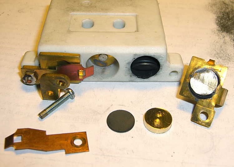
That solid model and the OpenSCAD code below include several refinements that don’t appear in the photos. In particular, the graceful slope on the top front will look a whole lot better than the abrasive adjustment required to fit the chunky first version into the pedal case:
Kenmore 158 – Hall speed control – prototype interior
On the other paw, that’s what rapid prototyping is all about. I had no way to measure that dimension, but building one to figure it worked pretty well.
Things that may / will need tweaking:
The centerline of the tubing lies on the same plane as the tops of the bosses under those three screws, but the bosses are not particularly flat. Perhaps some setscrews to fine-tune the height and front-to-back tilt angle?
The sketch had adjustable magnet positions; the as-built hardware doesn’t. It’s not clear they’re needed, although that depends on having exactly the right magnets.
The screws are #4 sheet metal and fit nicely into the metric holes; the original screws held a thin aluminum bracket in place, not that chunky block. I could recess the heads, but …
A 3D printed clamp holding the cable and strain relief bushing in place would be cuter than the sheet metal strap I bashed from scrap.
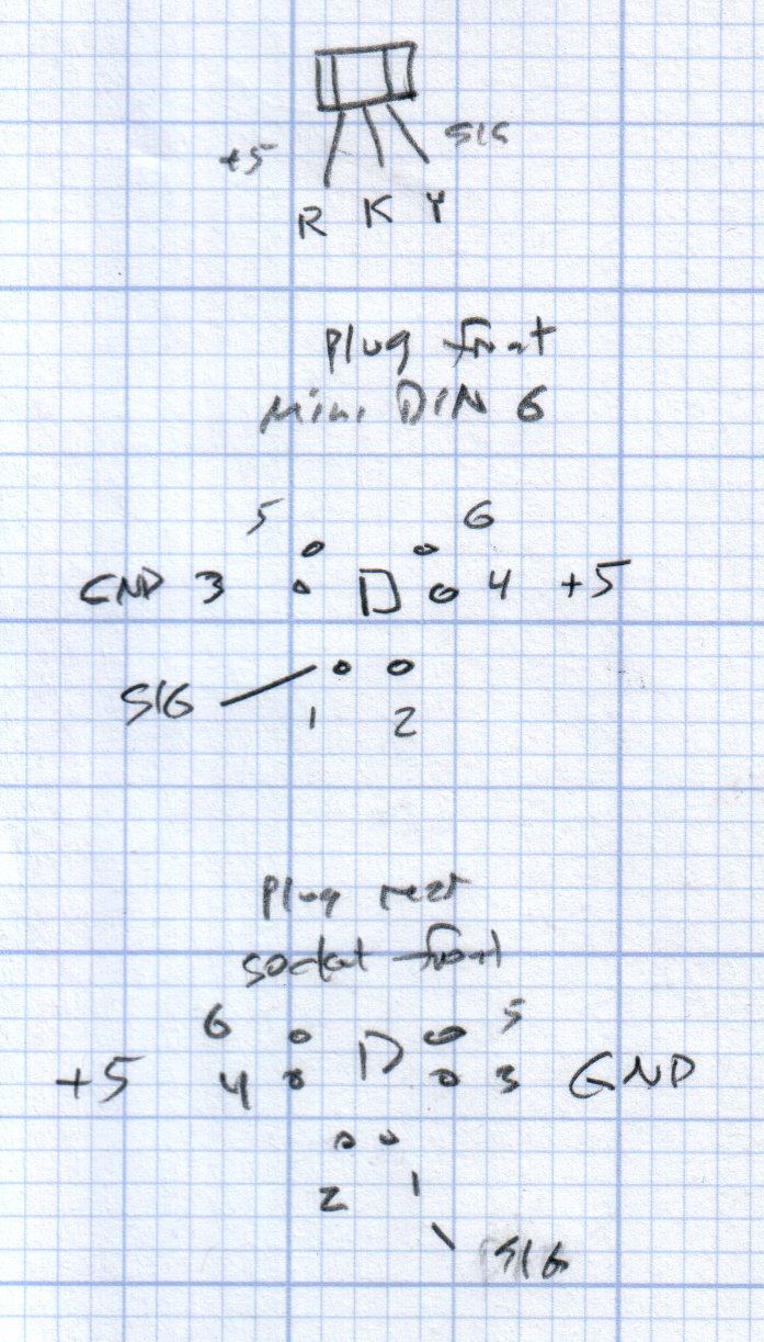
The far end of the cable terminates in a 6-pin mini-DIN connector, left over from the days when PCs (remember PCs?) had PS/2 mice & keyboards:
Kenmore 158 Improved Speed Control Pedal – cable wiring diagram
I’ll eventually put the emitter resistor into the circuit; these sensors work fine without it. The cable provides electrostatic shielding and I’m hoping the impedance is low enough that the motor won’t induce any noise. In any event, some low-pass filtering won’t slow down the response enough to notice.
Next, some measurements…
The OpenSCAD source code:
// Foot Control Sensor Mount
// Ed Nisley - KE4ZNU - June 2014

Layout = "Show";			// Plate Build Show

//- Extrusion parameters must match reality!
//  Print with 4 shells and 3 solid layers

ThreadThick = 0.20;
ThreadWidth = 0.40;

HoleWindage = 0.2;			// extra clearance

Protrusion = 0.1;			// make holes end cleanly

AlignPinOD = 1.70;			// assembly alignment pins: filament dia

function IntegerMultiple(Size,Unit) = Unit * ceil(Size / Unit);

//----------------------
// Dimensions
// Origin at center front edge of plate
//  Z = bottom surface

PlateSize = [85.0,53.0,15.0];						// overall plate size
MidZ = PlateSize[2]/2;								//  height of spring midline
PlateCornerRadius = 1.5;

FrontBevel = [0.0,15.0,5.5];						// Y from front, Z from centerline

ScrewHolesOC = [[-75.0/2,(37.0 - 14.0/2)],[-75.0/2,(37.0 + 14.0/2)],[75.0/2,37.0]];
ScrewHoleDia = 4.0;									// allow alignment slop around 3 mm / #4 screws

BossSize = [[12.0,28.0],[12.0,27.0]];				// mounting bosses: L R
BossOC = [[-75.0/2,37.0],[75.0/2,37.0]];

Stroke = 15.0;										// foot pedal actuation distance

Bushing = [5.6,23.0];								// outer brass tube
MainMagnet = [10.0,5.0];							// magnet on pushrod
BiasMagnet = [5.0,2.0];								// bias magnet behind Hall effect sensor
Spring = [9.0,8.0];									// recess for pushrod retracting spring
Washer = [10.0,1.0];								// recess for washer atop pushrod

OD = 0;												// subscripts for cylindrical objects
LEN = 1;

SensorThick = 2.0;									// Hall effect sensor on bias magnet
FilletLength = 0.75;								// glue fillet on main magnet

//----------------------
// Useful routines

module PolyCyl(Dia,Height,ForceSides=0) {			// based on nophead's polyholes

  Sides = (ForceSides != 0) ? ForceSides : (ceil(Dia) + 2);

  FixDia = Dia / cos(180/Sides);

  cylinder(r=(FixDia + HoleWindage)/2,
           h=Height,
           $fn=Sides);
}

module ShowPegGrid(Space = 10.0,Size = 1.0) {

  RangeX = floor(100 / Space);
  RangeY = floor(125 / Space);

	for (x=[-RangeX:RangeX])
	  for (y=[-RangeY:RangeY])
		translate([x*Space,y*Space,Size/2])
		  %cube(Size,center=true);

}

//----------------------
// Basic plate shape

module Plate() {

R = PlateCornerRadius;
Px = PlateSize[0]/2 - R;
Py = PlateSize[1] - R;
Sides = 4*4;

BevelAngle = atan2((MidZ - FrontBevel[2]),FrontBevel[1]);

echo("Bevel angle: ",BevelAngle);

	difference() {
		linear_extrude(height = PlateSize[2]) {
			hull() {
				translate([-Px,Py])
					circle(r=R,$fn=Sides);
				translate([Px,Py])
					circle(r=R,$fn=Sides);
				translate([Px,R])
					circle(r=R,$fn=Sides);
				translate([-(20-R),R])			// avoid left front boss
					circle(r=R,$fn=Sides);
				translate([-Px,20+R])			// avoid left front boss
					circle(r=R,$fn=Sides);
			}
		}

		translate([0,0,-Protrusion])						// screw bosses
			linear_extrude(height = (MidZ + Protrusion),convexity=2)
				for (i=[0:1])
					translate(BossOC[i])
						square(BossSize[i],center=true);

		translate([0,0,-Protrusion])						// plate mounting screws
			linear_extrude(height = 2*PlateSize[2] + Protrusion,convexity=3)
				for (i=[0:2])
					translate(ScrewHolesOC[i])
						rotate(180/6)
							circle(d=ScrewHoleDia,$fn=6);

		translate([0,0,MidZ + FrontBevel[2]])		// Front bevel
			rotate([BevelAngle,0,0])
				translate([0,0,PlateSize[2]])
					cube(2*PlateSize,center=true);

	}
}

//----------------------
// Modify plate for position sensor hardware

module Sensor() {

GluePort = [1.5*Bushing[OD],Bushing[OD]/2,PlateSize[2]];	// port for glue anchor around bushing

MagnetPort = [1.5*MainMagnet[OD],
			  (Stroke + MainMagnet[LEN] + FilletLength + SensorThick),
			  (PlateSize[2] + 2*Protrusion)];

	difference() {
		Plate();

		translate([0,(PlateSize[1] - Bushing[LEN] - Protrusion),MidZ])		// bushing
			rotate([-90,0,0])
				cylinder(d=Bushing[OD],h=PlateSize[1],$fn=6);

		translate([-GluePort[0]/2,										// bushing anchor opening
				  (PlateSize[1] - 0.66*Bushing[LEN] - GluePort[1]/2),
				  MidZ - GluePort[2] + Bushing[OD]/2])
			cube(GluePort,center=false);

		translate([0,(PlateSize[1] - Bushing[LEN] - MagnetPort[1]/2),MagnetPort[2]/2 - Protrusion])
			cube(MagnetPort,center=true);

		translate([0,(PlateSize[1] - Bushing[LEN] - MagnetPort[1] + Protrusion),MidZ])
			rotate([90,0,0])
				PolyCyl(BiasMagnet[OD],BiasMagnet[LEN] + Protrusion,6);

		translate([0,(PlateSize[1] + Protrusion),MidZ])
			rotate([90,0,0]) rotate(180/8)
				PolyCyl(Spring[OD],Spring[LEN] + Protrusion,8);

		translate([0,(PlateSize[1] + Protrusion),MidZ])
			rotate([90,0,0]) rotate(180/8)
				PolyCyl(Washer[OD],Washer[LEN] + Protrusion,8);

	}
}

ShowPegGrid();

if (Layout == "Plate") {
	Plate();
}

if (Layout == "Show")
	Sensor();

if (Layout == "Build") {
	translate([0,PlateSize[1]/2,PlateSize[2]])
		rotate([180,0,0])
			Sensor();
}