Ed Nisley's Blog: Shop notes, electronics, firmware, machinery, 3D printing, laser cuttery, and curiosities. Contents: 100% human thinking, 0% AI slop.
It’s much shorter than the actual pen, because there’s nothing happening beyond the top of the original HP pen body that will serve as an adapter holding this pen in the plotter. As before, the tip of the pen is at Z=0.
Some of the diameter values include a small Finagle Constant to provide a close sliding fit:
//-- Sakura Micron fiber-point pen

ExpRP = 0.15;						// expand critical sections (by radius)

//-- pen locates in holder against end of outer body

PenOutline = [
	[0,0],							//  0 fiber pen tip
	[0.6/2,0.0],[0.6/2,0.9],		//  1  ... cylinder
	[1.5/2,0.9],[1.5/2,5.3],		//  3 tip surround
	[4.7/2,5.8],					//  5 chamfer
	[4.9/2,12.3],					//  6 nose
//	[8.0/2,12.3],[8.0/2,13.1],		//  7 latch ring
//	[8.05/2,13.1],[8.25/2,30.5],	//  9 actual inner body
	[8.4/2 + ExpRP,12.3],[8.4/2 + ExpRP,30.5],	//  7 inner body - clear latch ring
	[9.5/2 + ExpRP,30.5],			//  9 outer body - location surface!
	[9.8/2 + ExpRP,50.0],			// 10 outer body - length > Body
	[7.5/2,50.0],					// 11 arbitrary length
	[7.5/2,49.0],					// 12 end of reservoir
	[0,49.0]						// 13 fake reservoir
	];

PenNose = PenOutline[6];
PenLatch = PenOutline[7];

PenOAL = PenOutline[11][HEIGHT];
The model excludes the latching ring that secures the pen cap, mostly because the fit was already snug enough.
Subtracting the Sakura pen from the HP pen body produces the adapter:
HP7475A – Sakura Micro Pen Adapter – solid model
The plug floating overhead and the cap standing on the bottom are frills that I added after the first few iterations. The plug seals the cut-off sections of the pen body, assuming that you will cut the pens to a more plotter-friendly length, and you’ll need two of them… a fact that didn’t penetrate my thick skull until I was confronted with the two ends of a cut-up pen. The flange on the bottom of the cap provides enough of a grip that you can actually pull the cap off; depending on the tolerances, it will be a very tight fit on the pen.
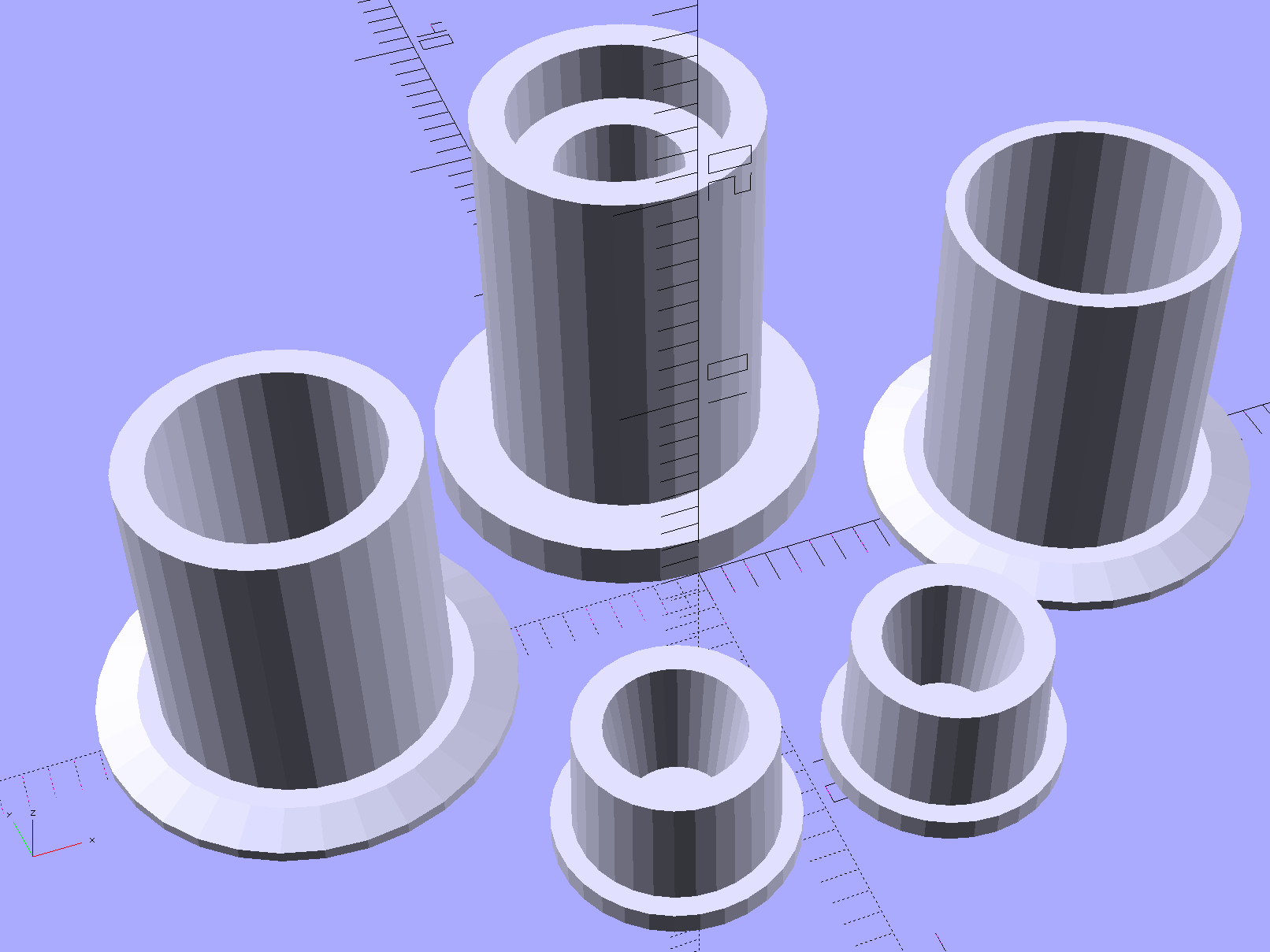
The solid model pieces rearranged for printing:
HP7475A – Sakura Micro Pen Adapter – build layout
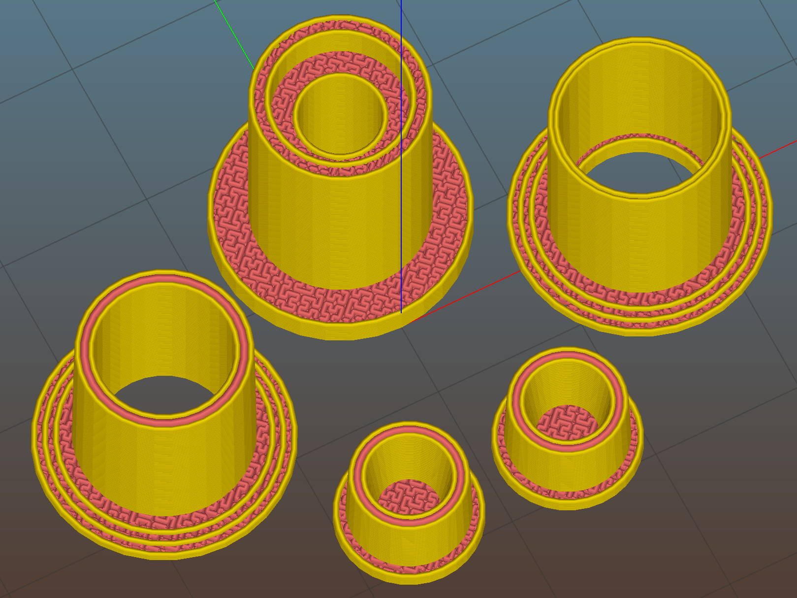
As before, splitting the HP pen body in the middle of the flange makes it build-able without supports. The first few passes didn’t include any of the other parts and had a slightly longer lower section (left front):
HP7475A – Sakura Micro Pen Adapter – on platform
I used Sakura Micron pens because they’re slightly smaller than my usual Sharpie Ultra Fine Point pens; Mary had been sketching quilting patterns with them. The difference between the Sakura and HP pen ODs amounts to barely more two filament widths, less than 1 mm:
HP 7475A – Sakura Pen Adapter – Slic3r Preview
Fortunately, Slic3r can dynamically adjust the thread width to eliminate voids between parallel outer walls with less than a thread width between them.
The interior step near the bottom of the part at the rear right in the picture locates the Sakura pen body inside the HP shell. In principle, that will put the tip at the same location as the HP pen tip, although making that happen required a bit of measurement fine-tuning:
HP7475A – Sakura Micro Pen Adapter – vs HP pen
I started out gluing the adapter halves together around a Sakura pen serving as a mandrel, but that didn’t work out well:
HP7475A – Sakura Micro Pen Adapter – gluing on pen
Although the IPS 4 adhesive didn’t attack the pen body, getting all the parts flying in formation required more dexterity than I could muster, plus that tape snippet didn’t seal the tip well at all. After doing a few adapters like that, I broke down and machined a steel mandrel with diameters matching the Sakura pen:
HP7475A – Sakura Micro Pen Adapter – mandrel
No, you can’t 3D print the mandrel.
You can see the discontinuities in the adapter shell, showing the internal step (in the right half) and the transition from 3D Honeycomb infill (just left of the flange) to a single thread of infill between the two outer walls (the rest of the left half).
After a few iterations, a full-length pen in an adapter produced some rather good-looking lines, if I do say so myself:
HP7475A – Sakura Micro Pen Adapter – first lines
That’s done in Etch A Sketch mode with the plotter’s front-panel buttons. The blob under the pen tip shows why you can’t let the pen linger on the paper for more than an instant…
You can buy new plotter pens for HP 7475A plotters at a bit over four bucks apiece and new-old-stock HP pens appear on eBay with similar prices, but what’s the fun in that?
You can refill the HP pens with liquid ink and continue plotting until the fiber tip wears out. That would limit me to the CMYK inkjet inks on the shelf, although I suppose investing in drafting inks might be amusing.
However, it should be feasible to build an adapter to hold an ordinary, albeit skinny, drawing / drafting pen, perhaps chopped down to be only a bit longer than the OEM plotter pens. That has the advantage of using cheap & readily available materials, doesn’t require much capital outlay, and, come to think of it, gives me a Digital Machinist column topic… [grin]
This is not, by any stretch of the imagination, a novel idea.
There’s a vague notion of converting the plotter into a vinyl / paper / stencil cutter, although I expect the snap-in pen holder can’t exert enough lateral force to hold a cutting knife in position, nor enough downward force to push the blade through the vinyl / paper / whatever. But ya never know until you try.
So, we begin…
A bit of digital caliper work provides a list of points defining the OEM pen body outline:
RADIUS = 0; // subscript for radius values
HEIGHT = 1; // ... height above Z=0

BodyOutline = [						// X values = (measured diameter)/2, Y as distance from tip
	[0.0,0.0],						//  0 fiber pen tip
//	[2.0/2,1.4],					//  1 ... taper (not buildable)
	[1.0/2,0.005],					//  1 ... faked point to remove taper
	[2.0/2,0.0],[2.0/2,2.7],		//  2 ... cylinder
	[3.7/2,2.7],[3.7/2,4.45],		//  4 tip surround
	[4.8/2,5.2],					//  6 chamfer
	[6.5/2,11.4],					//  7 rubber seal face
	[8.9/2,11.4],					//  8 cap seat
	[11.2/2,15.9],					//  9 taper to body
	[11.5/2,28.0],					// 10 lower body
	[13.2/2,28.0],[16.6/2,28.5],	// 11 lower flange = 0.5
	[16.6/2,29.5],[13.2/2,30.0],	// 13 flange rim = 1.0
	[11.5/2,30.0],					// 15 upper flange = 0.5
	[11.5/2,43.25],					// 16 upper body
	[0.0,43.25]						// 17 lid over reservoir
	];
Rather than computing the radius by hand, it’s easier to just divide the easily measured diameter by two and be done with it.
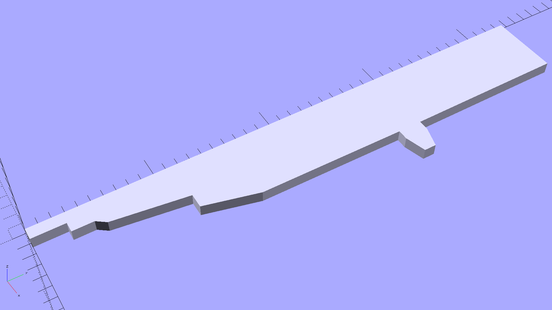
The point array defines a polygon in the XY plane:
HP7475A – HP Plotter Pen Body – plane polygon
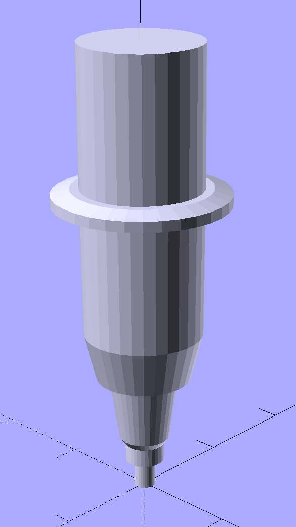
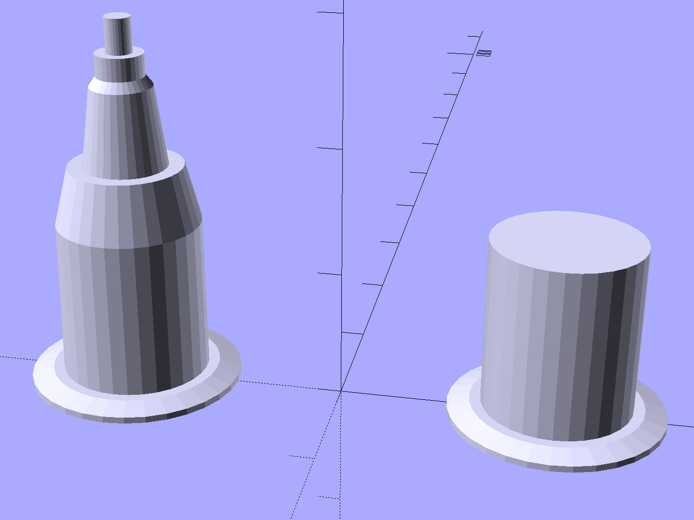
Then you feed that polygon into a rotate_extrude(), which spins up a reasonable simulacrum of a plotter pen:
HP7475A – HP Plotter Pen Body – solid model
I picked the coordinates to put the tip at (0,0,0) and converted the tapered fiber nib into a plain cylinder.
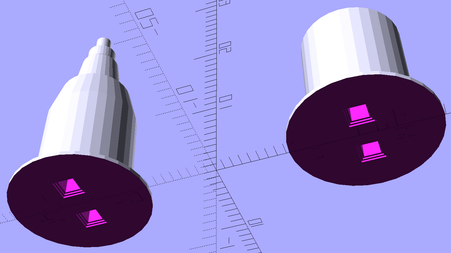
That shape is obviously impossible to print without vast amounts of support, but splitting it across the middle of the flange and rearranging the pieces works just fine:
HP7475A – HP Plotter Pen Body – build layout
A pair of alignment pin holes simplifies gluing the parts back together:
HP7475A – HP Plotter Pen Body – solid model – bottom
There’s a subtle problem lurking in that flange, which is 2.0 mm thick at the base and 1.0 mm thick at the rim. Splitting it in half requires each part to build correctly from an integral number of thread layers, so you must use a thread thickness (that’s in the Z direction) that divides evenly into the required height. I’ve been using 0.2 mm, which would produce a 1.2 mm rim.
Slicing at 0.25 mm produced a 2.1 mm flange with a 1.1 mm rim, suggesting that:
I could apply a Slic3r Modifier Mesh to print the flange with 0.10 mm layers, but that seems like entirely too much effort right now.
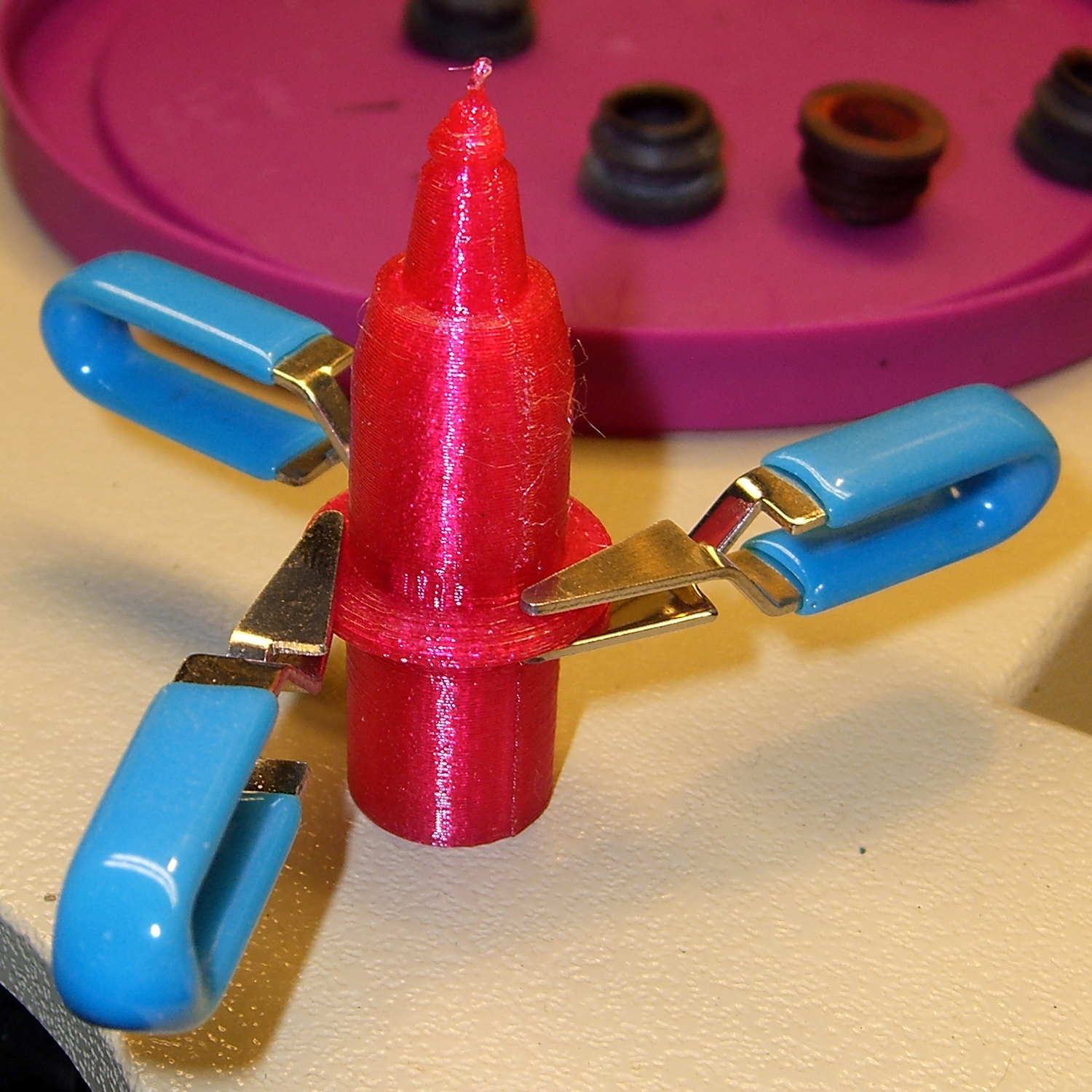
At the other end of the model, converting the tapered tip into a blunt cylinder didn’t save it from melting down:
HP 7475A Plotter Pen – solid PETG
It might be possible to reduce the printing speed enough to produce that tiny cylinder, but I needed just the upper body to verify that it fit correctly into the carousel:
HP 7475A Plotter Pen Body – in carousel
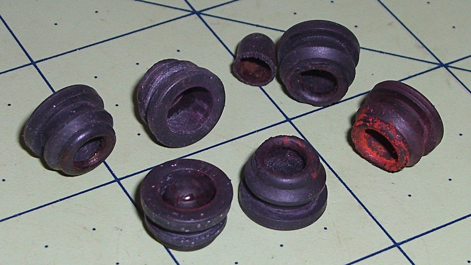
As you’d expect, the rubber boots that used to seal the pen tips have long since rotted out:
HP 7475A Carousel Rubber Boots
You can find sources for those boots, but at $252 (marked down to $144!) each, perhaps it’d be more feasible to gimmick up a two-part mold and cast silicone rubber duplicates; I could sell a set of six for $200 and get rich. Heck, I could even undercut their $40.32 two-year protection plan by a considerable margin.
Anyhow, the pen holder plucked it out of the carousel just like a real HP pen:
HP 7475A Plotter Pen Body – in holder
Note that the carousel and pen holder contact the flange and the cylindrical body, not either of the tapered sections down to the tip. That means I can carve away the entire bottom part of the body to make a drawing pen adapter…
The OpenSCAD source code includes a bunch of features & parts I’ll describe in the next few posts, but which certainly should not be regarded as final copy:
// HP7475A plotter pen adapters
// Ed Nisley KE4ZNU April 2015

Layout = "BuildBody";		// ShowKnife BuildKnife KnifeAdapter
							// ShowPen BuildPen Plug
							// ShowBody BuildBody
							// Pen Knife
							// Stabilizer BuildStabilizer

//- Extrusion parameters must match reality!

ThreadThick = 0.25;
ThreadWidth = 0.40;

HoleWindage = 0.2;

Protrusion = 0.1;			// make holes end cleanly

inch = 25.4;

function IntegerMultiple(Size,Unit) = Unit * ceil(Size / Unit);

//----------------------
// Dimensions
// Z=0 at pen tip!

NumSides = 8*4;						// number of sides on each "cylinder"

RADIUS = 0;							// subscript for radius values
HEIGHT = 1;							//   ... height above Z=0

//-- Original HP plotter pen, which now serves as a body for the actual pen

BodyOutline = [						// X values = (measured diameter)/2, Y as distance from tip
	[0.0,0.0],						//  0 fiber pen tip
//	[2.0/2,1.4],					//  1 ... taper (not buildable)
	[1.0/2,0.005],					//  1 ... faked point to remove taper
	[2.0/2,0.0],[2.0/2,2.7],		//  2 ... cylinder
	[3.7/2,2.7],[3.7/2,4.45],		//  4 tip surround
	[4.8/2,5.2],					//  6 chamfer
	[6.5/2,11.4],					//  7 rubber seal face
	[8.9/2,11.4],					//  8 cap seat
	[11.2/2,15.9],					//  9 taper to body
	[11.5/2,28.0],					// 10 lower body
	[13.2/2,28.0],[16.6/2,28.5],	// 11 lower flange = 0.5
	[16.6/2,29.5],[13.2/2,30.0],	// 13 flange rim = 1.0
	[11.5/2,30.0],					// 15 upper flange = 0.5
	[11.5/2,43.25],					// 16 upper body
	[0.0,43.25]						// 17 lid over reservoir
	];

TrimHeight = BodyOutline[9][HEIGHT];		// cut off at top of lower taper
SplitHeight = (BodyOutline[11][HEIGHT] + BodyOutline[14][HEIGHT])/2;	// middle of flange

FlangeOD = 2*BodyOutline[13][RADIUS];
FlangeTop = BodyOutline[15][HEIGHT];

BodyOD = 2*BodyOutline[16][RADIUS];
BodyOAL = BodyOutline[17][HEIGHT];

echo(str("Trim: ",TrimHeight));
echo(str("Split: ",SplitHeight));

BuildSpace = FlangeOD;

//-- Sakura Micron fiber-point pen

ExpRP = 0.15;						// expand critical sections (by radius)

//-- pen locates in holder against end of outer body

PenOutline = [
	[0,0],							//  0 fiber pen tip
	[0.6/2,0.0],[0.6/2,0.9],		//  1  ... cylinder
	[1.5/2,0.9],[1.5/2,5.3],		//  3 tip surround
	[4.7/2,5.8],					//  5 chamfer
	[4.9/2,12.3],					//  6 nose
//	[8.0/2,12.3],[8.0/2,13.1],		//  7 latch ring
//	[8.05/2,13.1],[8.25/2,30.5],	//  9 actual inner body
	[8.4/2 + ExpRP,12.3],[8.4/2 + ExpRP,30.5],	//  7 inner body - clear latch ring
	[9.5/2 + ExpRP,30.5],			//  9 outer body - location surface!
	[9.8/2 + ExpRP,50.0],			// 10 outer body - length > Body
	[7.5/2,50.0],					// 11 arbitrary length
	[7.5/2,49.0],					// 12 end of reservoir
	[0,49.0]						// 13 fake reservoir
	];

PenNose = PenOutline[6];
PenLatch = PenOutline[7];

PenOAL = PenOutline[11][HEIGHT];

PlugOutline = [
	[0,0],							// 0 center of lid
	[9.5/2,0.0],[9.5/2,1.0],		// 1 lid rim
	[7.8/2,1.0],					// 3 against end of pen
	[7.3/2,6.0],					// 4 taper inside pen
	[5.3/2,6.0],					// 5 against ink reservoir
	[4.0/2,1.0],					// 6 taper to lid
	[0.0,1.0]						// 7 flat end of taper
	];

PlugOAL = PlugOutline[5][HEIGHT];

//   cap locates against end of inner body at latch ring
//-- cap origin is below surface to let pen tip be at Z=0

CapGap = 1.0;						// gap to adapter body when attached
CapGripHeight = 2.0;				// thickness of cap grip flange
CapTipClearance = 1.0;				// clearance under fiber tip

CapOffset = -(CapGripHeight + CapTipClearance);	// align inside at pen tip Z=0

CapOutline = [
	[0,CapOffset],									// 0 base
	[FlangeOD/2,CapOffset],							// 1 finger grip flange
	[FlangeOD/2,CapOffset + CapGripHeight],			// 2  ... top
	[BodyOD/2,CapOffset + CapGripHeight],			// 3 shaft
	[BodyOD/2,TrimHeight - CapGap],					// 4  ... top with clearance
	[PenLatch[RADIUS],TrimHeight - CapGap],			// 5 around pen latch ring
	[PenLatch[RADIUS],PenNose[HEIGHT]],				// 6  ... location surface!
	[PenNose[RADIUS] + ExpRP,PenNose[HEIGHT]],		// 7 snug around  nose
	[PenNose[RADIUS] + ExpRP,-CapTipClearance],		// 8 clearance around tip
	[0,-CapTipClearance],							// 9  ... bottom
	];

//-- Drag knife holder

ExpRK = 0.30;						// expand critical sections (by radius)
AdjLen = 2.0;						// allowance for adjustment travel

KnifeOutline = [
	[0,0],							//  0 blade point (actually 0.25 mm offset)
	[1.0/2,0.0],					//  1  ... blunt end
	[1.0/2,4.0],					//  2  ... cylinder
	[2.0/2,4.0],					//  3 shank
	[2.0/2,5.9],					//  4  .. at bearing
	[6.0/2,5.9],					//  5 holder - shell
	[7.3/2 + ExpRK,8.3],			//  6 holder - taper to body
	[7.3/2 + ExpRK,21.0 - AdjLen],	//  7 holder body
	[8.8/2 + ExpRK,22.0 - AdjLen],	//  8 holder - threads bottom
	[8.8/2 + ExpRK,25.0],[9.0/2 + ExpRK,26.0],		//  9 clear threads to reduce friction
	[9.0/2 + ExpRK,32.0],[8.8/2 + ExpRK,33.0],		// 11  ... end clearance
	[8.8/2 + ExpRK,42.5 - AdjLen],	// 13 holder - threads top = locknut bottom
	[12.5/2,42.5 - AdjLen],			// 14 knurled locknut - adjustment travel
	[12.5/2,45.8],					// 15 knurled locknut - top
	[11.0/2,45.8],					// 16 holder - adjusting knurl
	[11.0/2,52.0],					// 17 holder - top surface
	[3.0/2,52.0],[3.0/2,57.2],		// 18 spring post
	[0.0,57.2]						// 19 end of post
	];

ThreadLength = KnifeOutline[13][HEIGHT] - KnifeOutline[8][HEIGHT];

//-- Plotter pen holder stabilizer

HolderPlateThick = 3.0;				// thickness of plate atop holder
RimHeight = 5.0;					// rim around sides of holder
RimThick = 2.0;

HolderOrigin = [17.0,12.2,0.0];		// center of pen relative to polygon coordinates

HolderZOffset = 30.0;				// top of holder in pen-down position
HolderTopThick = 1.7;				// top of holder to top of pen flange
HolderCylinderLength = 17.0;		// length of pen support structure

HolderKnifeOffset = -2.0;			// additional downward adjustment range (not below top surface)

LockScrewInset = 3.0;				// from right edge of holder plate
LockScrewOD = 2.0;					// tap for 2.5 mm screw

// Beware: update hardcoded subscripts in Stabilizer() when adding / deleting point entries

HolderPlate = [
	[8.6,18.2],[8.6,23.9],			// 0 lower left corner of pen recess
	[13.9,23.9],[13.9,30.0],		// 2
//	[15.5,30.0],[15.5,25.0],		// 4 omit middle of support beam
//	[20.4,25.0],[20.4,30.0],		// 6
	[22.7,30.0],[22.7,27.5],		// 4
	[35.8,27.5],[35.8,20.7],		// 6 spring box corner
	[43.0,20.7],					// 8
	[31.5,0.0],						// 9
//	[24.5,0.0],[24.5,8.0],			// 10 omit pocket above pen clamp
//	[22.5,10.0],[22.5,16.5],		// 12
//	[20.5,18.2]						// 14
	[13.6,0.0],						// 10
	[8.6,5.0]						// 11
	];

BeamWidth = HolderPlate[4][0] - HolderPlate[2][0];

//----------------------
// Useful routines

module PolyCyl(Dia,Height,ForceSides=0) {			// based on nophead's polyholes

  Sides = (ForceSides != 0) ? ForceSides : (ceil(Dia) + 2);

  FixDia = Dia / cos(180/Sides);

  cylinder(r=(FixDia + HoleWindage)/2,
           h=Height,
	   $fn=Sides);
}

//- Locating pin hole with glue recess
//  Default length is two pin diameters on each side of the split

PinOD = 1.75;
PinOC = BodyOD / 2;

module LocatingPin(Dia=PinOD,Len=0.0) {

	PinLen = (Len != 0.0) ? Len : (4*Dia);

	translate([0,0,-ThreadThick])
		PolyCyl((Dia + 2*ThreadWidth),2*ThreadThick,4);

	translate([0,0,-2*ThreadThick])
		PolyCyl((Dia + 1*ThreadWidth),4*ThreadThick,4);

	translate([0,0,-(Len/2 + ThreadThick)])
		PolyCyl(Dia,(Len + 2*ThreadThick),4);

}

module LocatingPins(Length) {
	for (i=[-1,1])
	translate([0,i*PinOC/2,0])
		rotate(180/4)
		LocatingPin(Len=Length);
}

//----------------------
// Basic shapes

//-- HP plotter pen body

module Body() {
	render(convexity=3)
		rotate_extrude($fn=NumSides)
			polygon(points=BodyOutline);
}

//-- HP plotter pen holder
//   the trim block offsets use magic numbers from the HolderPlate outline

module Stabilizer() {

	difference() {
		union() {
			translate(-HolderOrigin)													// put center of pen at origin
				difference() {
						render(convexity=4)
						linear_extrude(height=(HolderPlateThick + RimHeight))			// overall flange around edges
							offset(r=RimThick)
									polygon(points=HolderPlate);

						render(convexity=4)
						translate([0,0,-Protrusion])									// recess for pen holder plate
							linear_extrude(height=(RimHeight + Protrusion))
								polygon(points=HolderPlate);

						translate([HolderPlate[7][0] - Protrusion,HolderPlate[7][1] - Protrusion,-Protrusion])	// trim spring box from top plate
							cube([30,20,(RimHeight + HolderPlateThick + 2*Protrusion)]);

						translate([27.0,HolderPlate[6][1] - Protrusion,-Protrusion])	// trim pivot plate clearance
							cube([30,20,(RimHeight + HolderPlateThick + 2*Protrusion)]);

						translate([HolderPlate[2][0],20,-Protrusion])					// trim left support beam
							cube([BeamWidth,20,(RimHeight + Protrusion)]);

						translate([HolderPlate[9][0] - LockScrewInset,RimThick,RimHeight - HolderTopThick - LockScrewOD/2])												// lock screw on front edge
							rotate([90,0,0])
								rotate(180/4)
									PolyCyl(LockScrewOD,3*RimThick);					// hold-down screw hole
				}

			translate([0,0,(RimHeight - HolderCylinderLength + Protrusion)])
				cylinder(d=BodyOD,h=HolderCylinderLength + Protrusion,$fn=NumSides);				// surround knife threads
		}

		translate([0,0,-HolderZOffset + HolderKnifeOffset])
			Knife();
	}
}

//-- Sakura drawing pen body

module Pen() {
	rotate_extrude($fn=NumSides)
		polygon(points=PenOutline);
}

//-- Plug for top of Sakura pen

module Plug() {
	render(convexity = 2)
		rotate_extrude($fn=NumSides)
			polygon(points=PlugOutline);
}

//-- Cap for tip of Sakura pen

module Cap() {
	render(convexity = 2)
		rotate_extrude($fn=NumSides)
			polygon(points=CapOutline);
}

//-- Sakura pen adapter

module PenAdapter(TrimZ = false) {

Trans = TrimZ ? - TrimHeight : 0;

	render(convexity=5)
		translate([0,0,Trans])
			difference() {
				Body();
				Pen();
				translate([0,0,TrimHeight/2])
					cube([2*FlangeOD,2*FlangeOD,TrimHeight],center=true);
			}
}

//-- Roland knife body

module Knife() {
	render(convexity=3)
		rotate_extrude($fn=NumSides)
			polygon(points=KnifeOutline);
}

//-- Roland knife adapter

module KnifeAdapter(TrimZ = false) {

Trans = TrimZ ? - TrimHeight : 0;

	render(convexity=5)
		translate([0,0,Trans])
			difference() {
				Body();
				Knife();
				translate([0,0,TrimHeight/2])
					cube([2*FlangeOD,2*FlangeOD,TrimHeight],center=true);
			}
}

//----------------------
// Build it

if (Layout == "Pen")
	Pen();

if (Layout == "Knife")
	Knife();

if (Layout == "Stabilizer")
	Stabilizer();

if (Layout == "ShowBody")
	Body();

if (Layout == "BuildBody")
	difference() {
		union() {
			translate([BuildSpace,0,-SplitHeight])
				Body();
			rotate([180,0,0])
				translate([-BuildSpace,0,-SplitHeight])
					Body();
		}
		translate([0,0,-BodyOAL])
			cube(2*BodyOAL,center=true);
		for (i = [-1,1])
			translate([i*BuildSpace,0,0])
				LocatingPins(5.0);
	}

if (Layout == "Plug")
	Plug();

if (Layout == "KnifeAdapter")
	KnifeAdapter();

if (Layout == "ShowPen") {

	color("AntiqueWhite") {
		Pen();
		translate([-1.5*BodyOD,0,0])
			Pen();
	}
	color("Magenta",0.35) {
		translate([0,0,PlugOAL + PenOAL + 3.0])
			rotate([180,0,0])
				Plug();
		PenAdapter();
		Cap();
	}
	color("Magenta") {
		translate([1.5*BodyOD,0,PlugOAL + PenOAL + 3.0])
			rotate([180,0,0])
				Plug();
		translate([1.5*BodyOD,0,0]) {
			PenAdapter();
			Cap();
		}
	}

}

if (Layout == "ShowKnife") {

	color("Goldenrod") {
		Knife();
		translate([-1.5*BodyOD,0,0])
			Knife();
	}
	color("Magenta",0.35)
		KnifeAdapter();
	color("Magenta") {
		translate([1.5*BodyOD,0,0])
			KnifeAdapter();
	}

}

if (Layout == "BuildPen") {

	translate([0,BuildSpace/2,0])
		Plug();
	translate([0,-BuildSpace/2,-CapOffset])
		Cap();

	difference() {
		union() {
			translate([BuildSpace,0,-SplitHeight])
				PenAdapter(false);
			rotate([180,0,0])
				translate([-BuildSpace,0,-SplitHeight])
					PenAdapter(false);
		}
		translate([0,0,-BodyOAL])
			cube(2*BodyOAL,center=true);
	}

}

if (Layout == "BuildKnife") {

	difference() {
		union() {
			translate([BuildSpace,0,-SplitHeight])
				KnifeAdapter(false);
			rotate([180,0,0])
				translate([-BuildSpace,0,-SplitHeight])
					KnifeAdapter(false);
		}
		translate([0,0,-BodyOAL])
			cube(2*BodyOAL,center=true);
	}

}

if (Layout == "BuildStabilizer") {

	translate([0,0,(HolderPlateThick + RimHeight)])
		rotate([0,180,0])
			Stabilizer();
}
I’d originally secured the rear fender to the steel strap connecting the chainstays on Mary’s Tour Easy with a cable tie: small, simple, light weight, reliable. Unfortunately, that put the end of the fender just slightly lower than the strap and, I fear, sprayed water all over the strap, where it worked its way through a paint flaw and rusted the steel under the paint. A simple metal clip would chew its way through the pain[t] on the strap, so, seeing as how we’re living in the future…
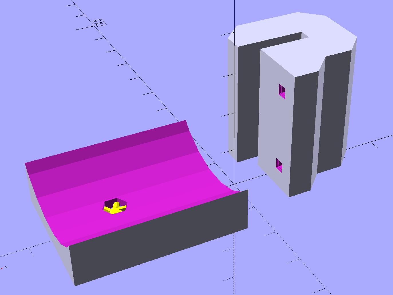
The C-shaped block on the top grips the steel cross-strap, the trough fits the fender’s curve, the little spider supports the inside of the nut recess, and a pair of alignment pin holes (one visible) help during gluing:
Tour Easy Rear Fender Bracket – solid model – show
Although it’s tempting to 3D print both parts as a single unit, laying them out like this aligns the threads for best strength in each piece:
Tour Easy Rear Fender Bracket – solid model – build
Pressing the bracket on the glass slab (flat side up, nubblies on the bottom) with the clamps in place finished the job. The slightly crushed support spider from the nut recess sits in the foreground:
Tour Easy rear fender bracket – gluing
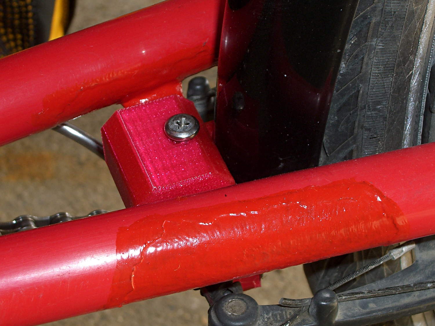
Magenta PETG matches the red Tour Easy paint surprisingly well:
Tour Easy – rear fender bracket – installed – top
From below, you can see why the top block can’t extend all the way to the bottom of the fender mount:
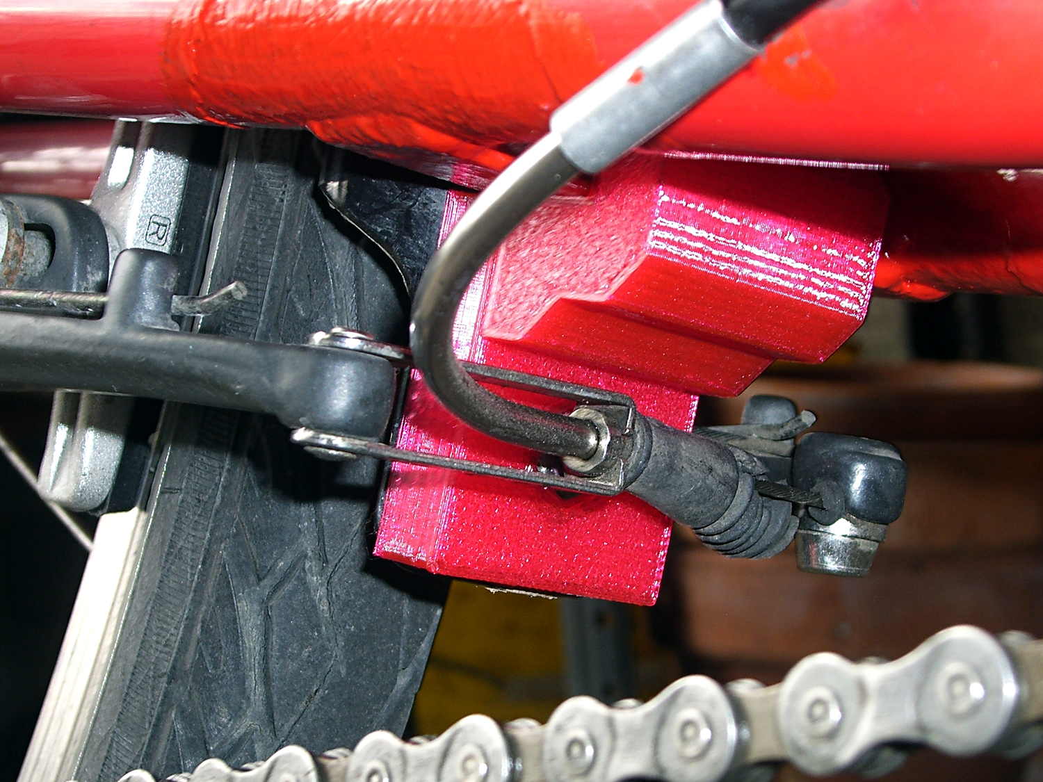
Tour Easy rear fender bracket – installed
That rubber boot needs replacing in the worst possible way, but I didn’t have anything suitable on hand and wouldn’t dismount that cable even if I had; cables never go back on properly.
Alas, because the brakes weren’t mounted when I did the measurements, I had to build one to find out why a long block wouldn’t work:
Tour Easy rear fender bracket – long back
The screw atop the block (on the left in that picture) presses a small plastic slug against the steel strap, in the hopes it won’t chew through the paint quite as rapidly. The screws & nuts are stainless, so at least they’ll survive for a while.
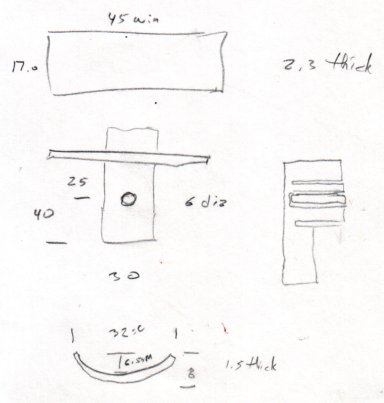
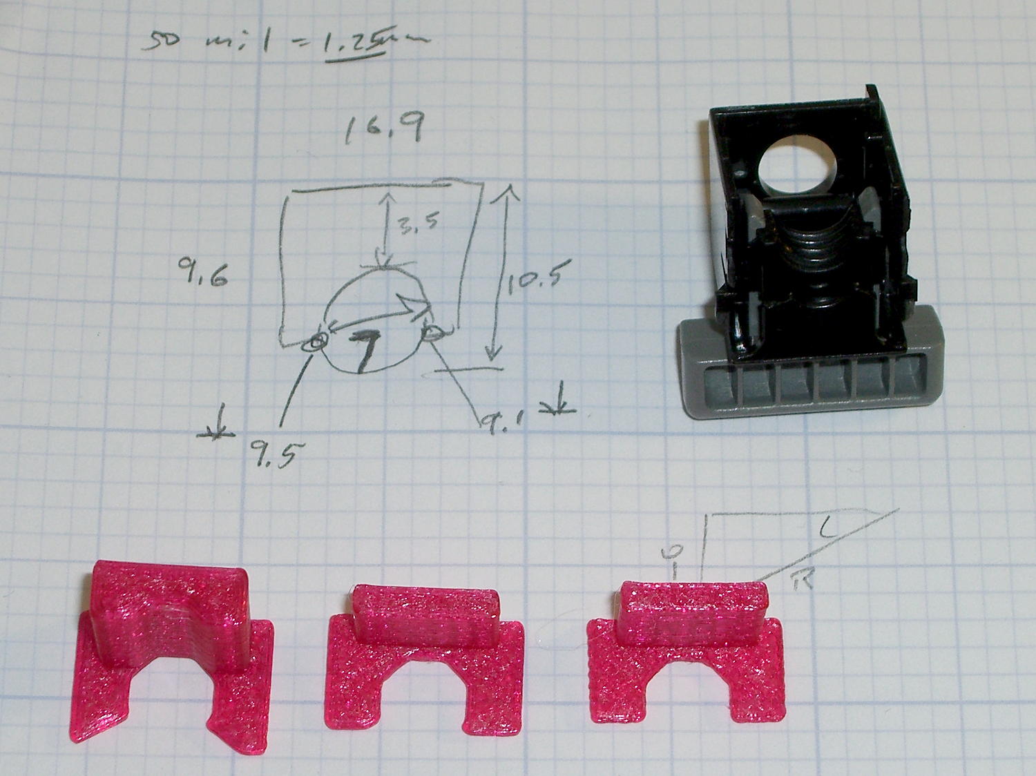
The curve in the trough comes from the chord equation applied to these crude measurements:
Tour Easy Rear Fender Bracket – measurement doodle
Fortunately, it’s tucked into a spot where nobody ever looks…
While replacing the well-worn sprocket / chain / chainrings on Mary’s bike, I finally got around to repairing some damaged paint tucked in an inconvenient spot…
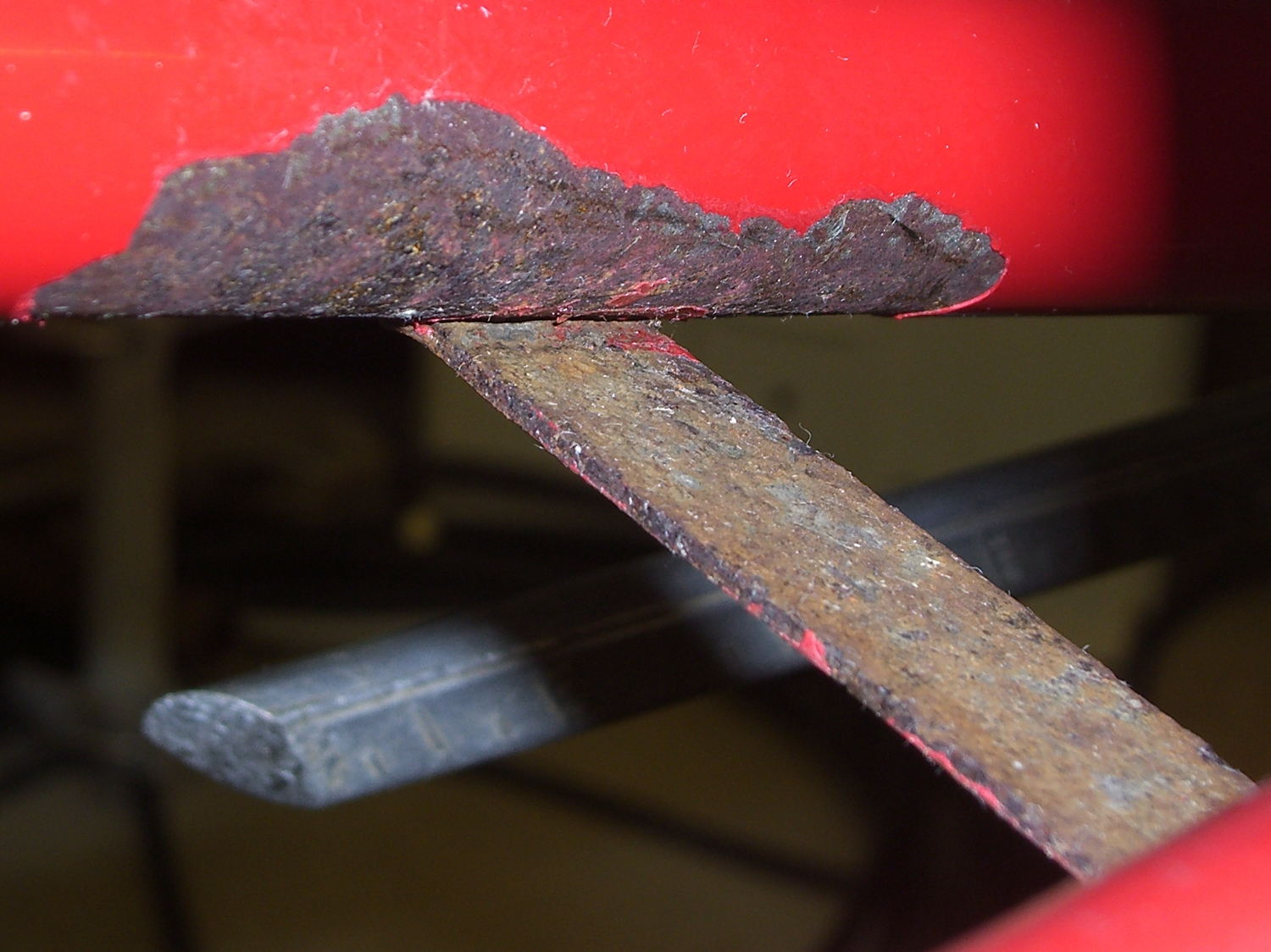
Over the years, a flaw in the paint underneath the strap connecting the chainstays on Mary’s Tour Easy let in enough moisture to dislodge the paint over a considerable area. I chipped off the loose paint and used Evapo-Rust to convert the oxide to phosphate; there’s not much damage to the steel parts, despite what it may look like in the pictures.
A top view from the right rear, minus the wheel & fender, looking toward the left chainstay:
Tour Easy – rusted chainstay strap
Two epoxy fillets in the concave sections where the strap meets the chainstays should eliminate problems in those sections forever more:
Tour Easy – chainstay strap – epoxy fillet
Some rusty-metal primer and a few coats of red paint conceal most of the ugliness:
Tour Easy – rear fender bracket – installed – top
It’ll never be mistaken for showroom quality, but our bikes are tools, not art objects.
The obviously 3D printed red block in the middle of the strap holds the fender in place, about which more tomorrow…
Having run off four quick prints with identical settings, I measured the thickness of the skirt threads around each object:
Skirt Thread Consistency
They’re all slightly thicker than the nominal 0.25 mm layer thickness, but centered within ±0.02 mm of the average 0.27 mm. Tweaking the G92 offset in the startup G-Code by 0.02 would fix that.
The 0.29 mm skirt surrounded the first object, which had a truly cold start: 14 °C ambient in the Basement Laboratory. After that, they’re pretty much identical.
Some informal measurements over a few days suggests the actual repeatability might be ±0.05 mm, which is Good Enough for layers around 0.20 to 0.25 mm.
The larger skirt suggests that the platform has a slight tilt, but the caliper resolution is only 0.01 mm.
When I realigned everything after installing the V4 hot end, the last set of thinwall boxes looked like this:
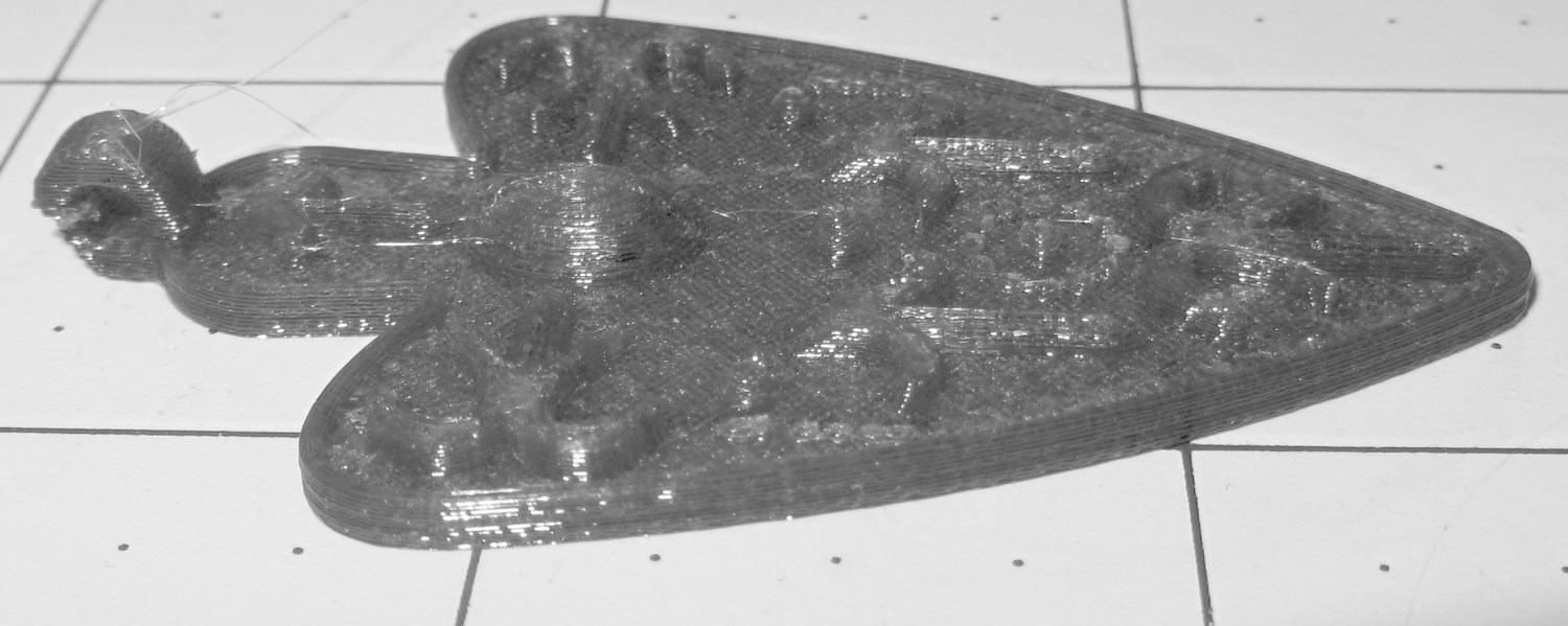
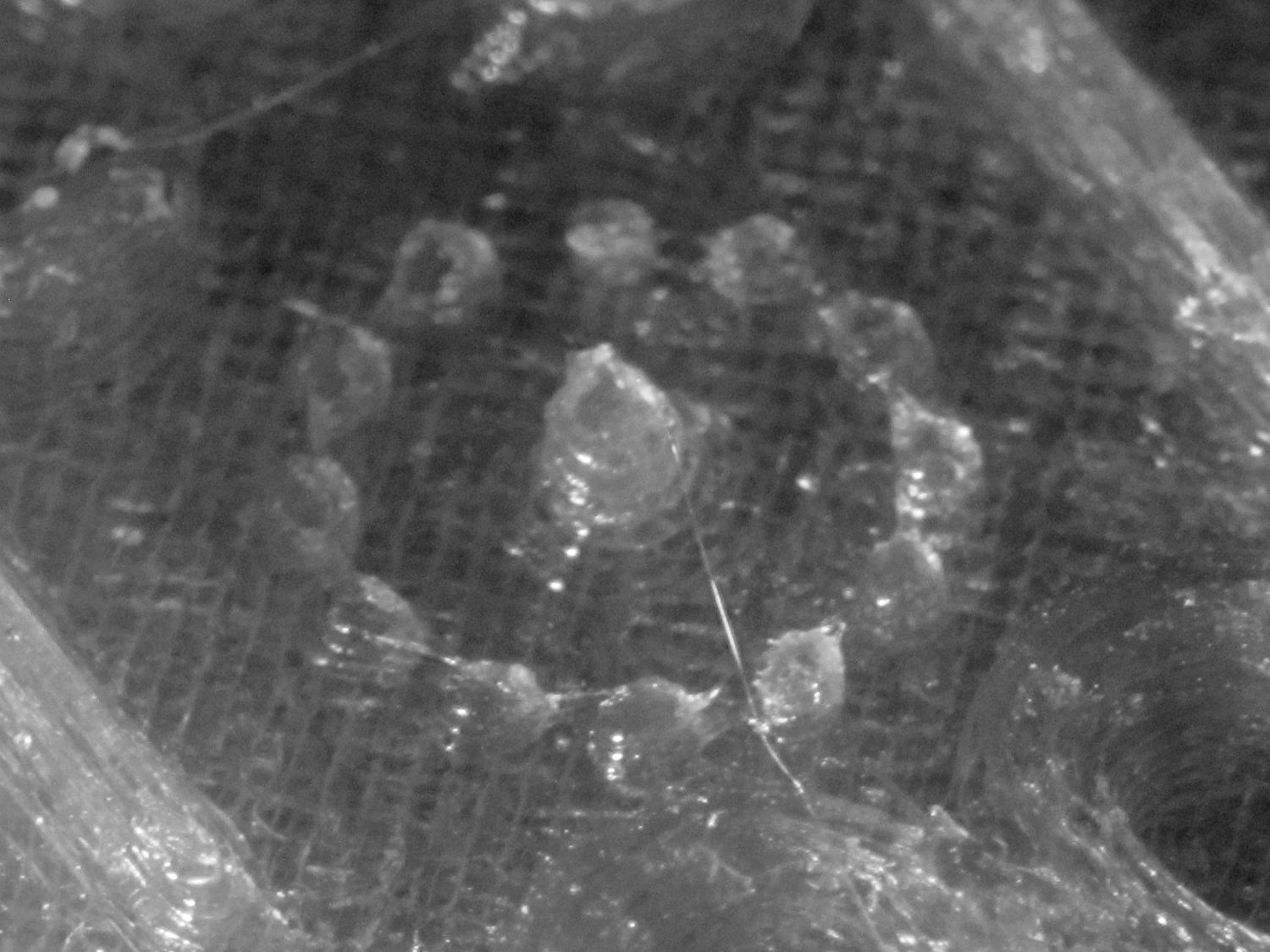
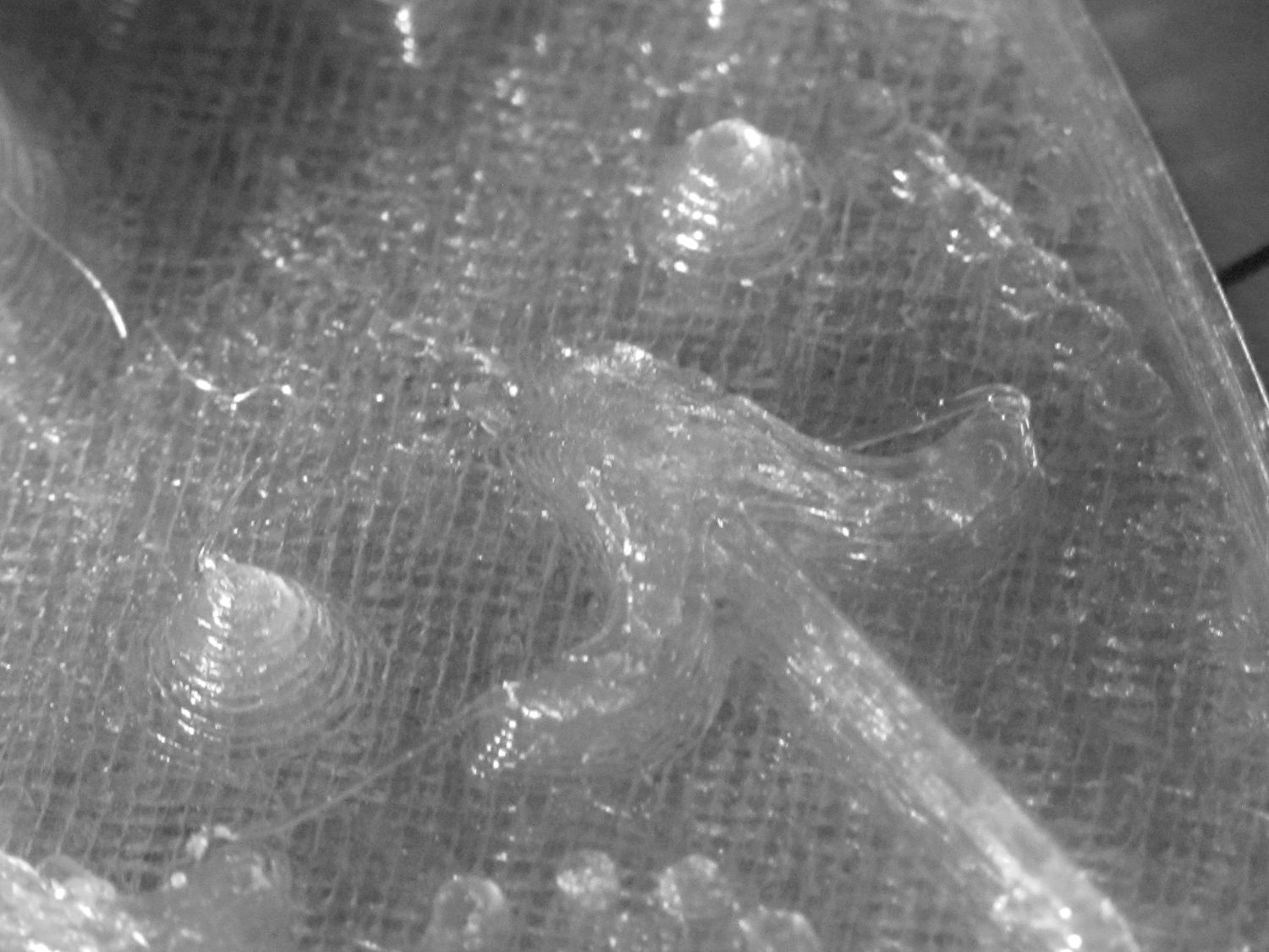
I also tried using the camera in its B&W mode to discard the color information up front:
Necklace Heart – circle detail
It’s taken through the macro adapter with the LEDs turned off and obviously benefits from better lighting, with an LED flashlight at grazing incidence. You can even see the Hilbert Curve top infill.
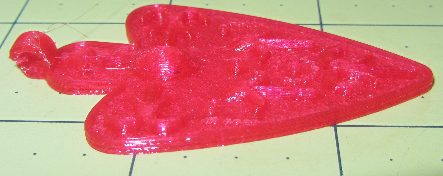
The object of the exercise was to see if those tiny dots would print properly, which they did:
Necklace Heart – dots detail
Now, admittedly, PETG still produces fine hairs, but those dots consist of two layers and two thread widths, so it’s a harsh retraction test.
A look at the other side:
Necklace Heart – detail
All in all, both the object and the pix worked out much better than I expected.
Leaving the camera in full color mode and processing the images in The GIMP means less fiddling with the camera settings, which seems like a net win.
First up: it’s not our projector, which means the usual Rules of Engagement do not apply.
A few small black plastic fragments fell out of the Epson S5 projector’s carry bag, the front foot wouldn’t remain extended, and, as one might expect, the two incidents were related. Mary needed it for the gardening class she was teaching the next evening, sooooo…
A pair of plastic snaps release the entire foot assembly from the front of the projector:
Epson S5 Projector Foot – assembled
It became obvious that we didn’t have all the fragments, but it was also obvious that, even if we had the pieces, a glued assembly wouldn’t last very long.
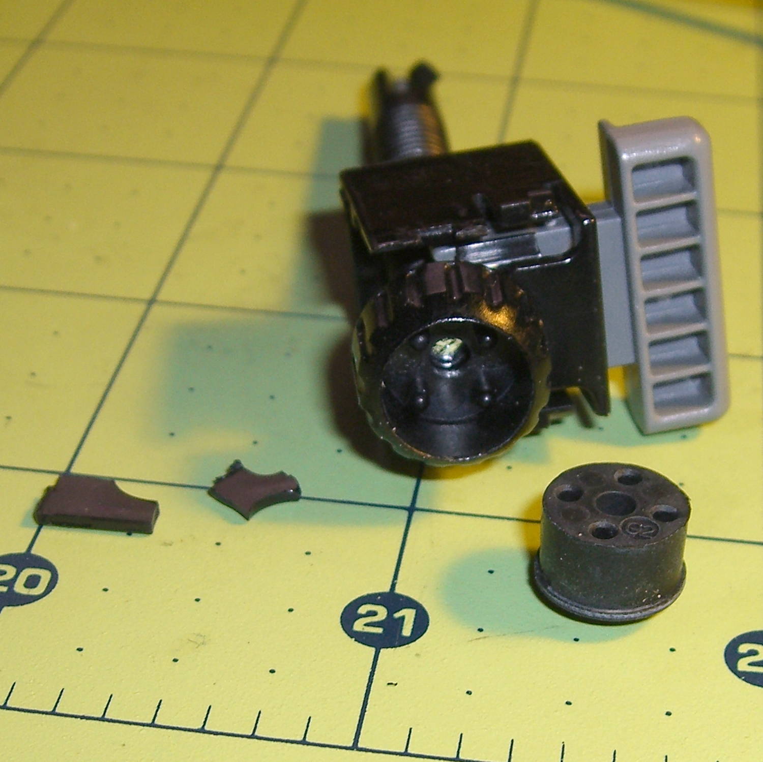
The threaded plastic stem surrounds a steel pin that’s visible when you remove the rubber foot pad. That pin holds the latch on the end of the stem outward, so that the stem can’t fall out. Drive out the pin with a (wait for it) pin punch inserted from the foot pad end, which reveals the broken plastic doodad:
Epson S5 Projector Foot – stem removed
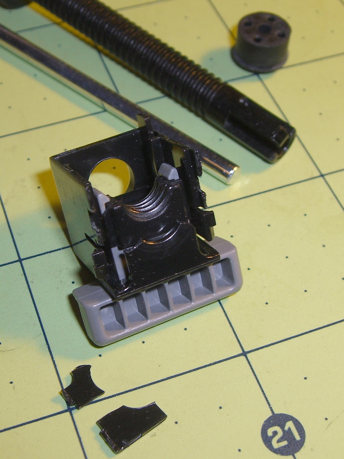
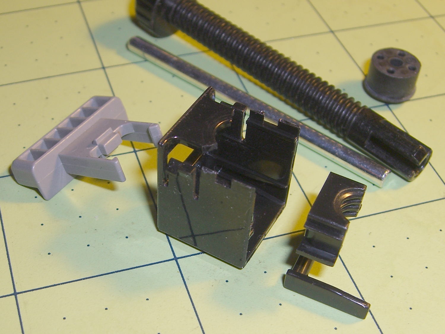
Release the latches on the gray handle and the intricate half-nut that engages the threaded stem slides out:
Epson S5 Projector Foot – disassembled
A plastic spring in the boxy shell pushes the gray handle and half-nut against the stem, holding the stem in place. Pushing the gray handle upward (on the projector, downward in the picture, yes, your fingertip can feel those ribs just fine) pulls the half-nut away from the stem and lets the stem slide freely. With the stem extended, the projector leans on the stem, pushes it against the half-nut, and you can fine-tune the angle by turning the stem; the splines around the rubber foot encourage that. You can pull the stem outward without activating the latch, which probably broke the fragile plastic plate.
A doodle showing the estimated measurements, plus three 3D printed prototypes required to get a good fit:
Epson S5 Projector Foot – measurements and versions
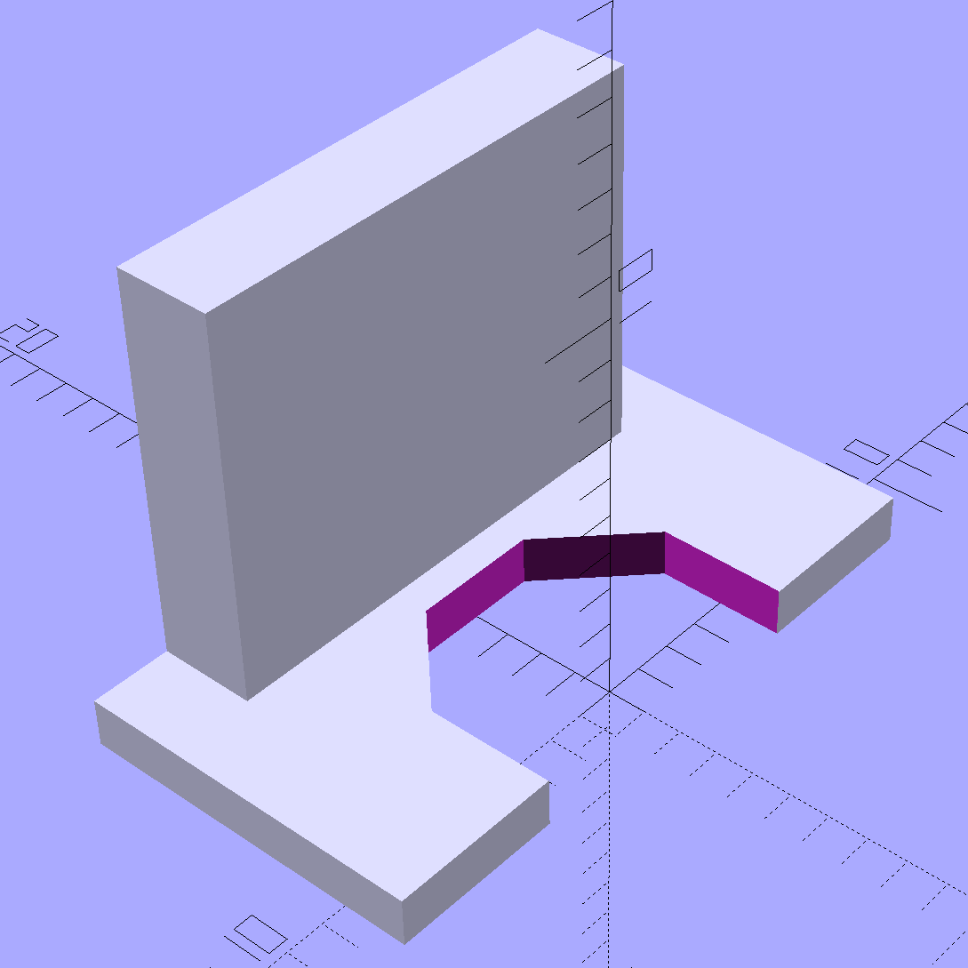
The solid model looks about like you’d expect:
Epson S5 Projector foot latch – solid model
The first version (leftmost of the three sitting on the doodle, above) had angled ends on the tabs that I intended to match up with the stubs remaining on the OEM latch. The part fit better with shorter tabs and the angles vanished on third version; the statements remain in the OpenSCAD source, but the short tabs render them moot.
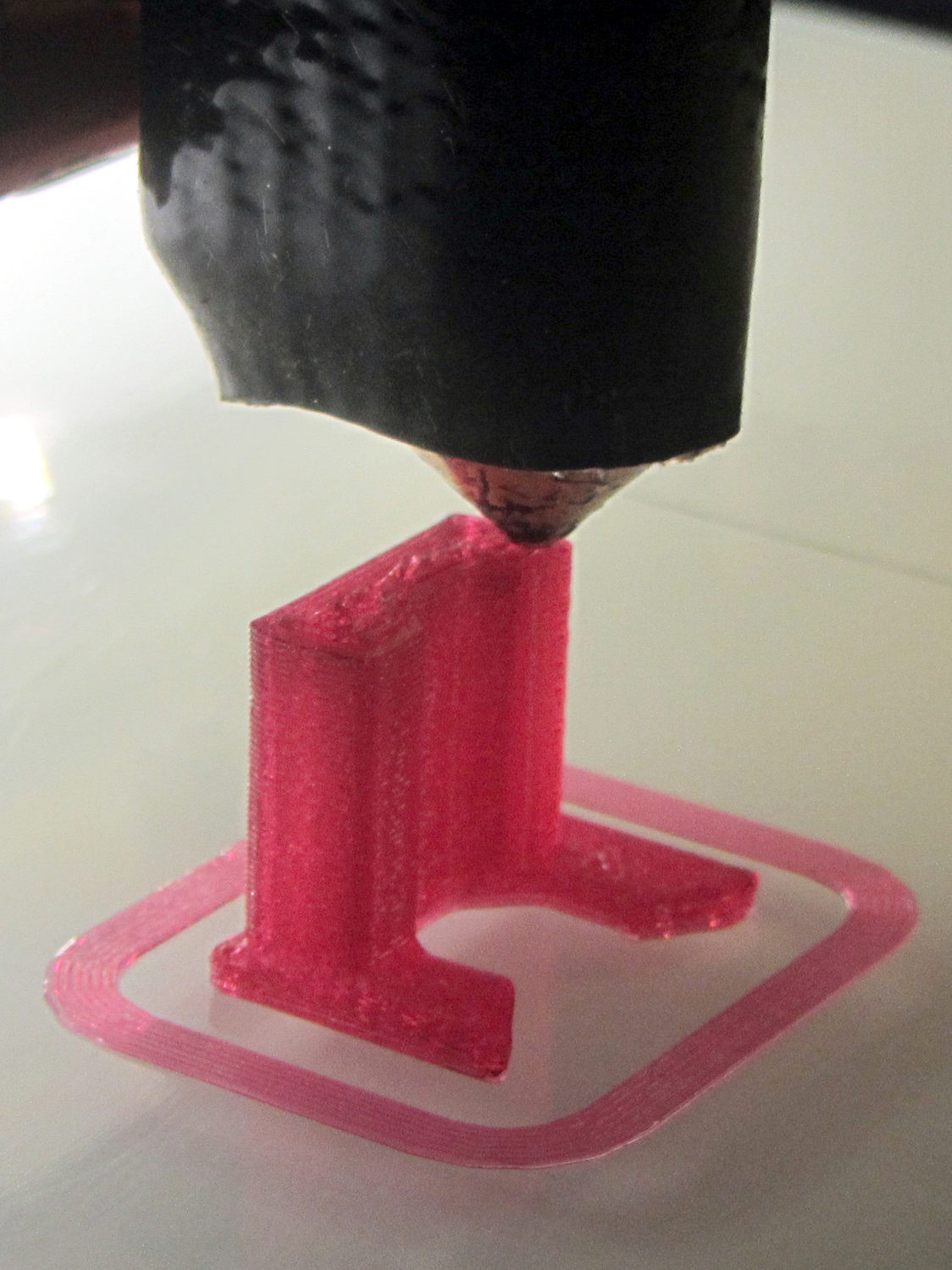
Apparently I got the cooling & fan & minimum layer time pretty close to right for PETG, as each of those three towers printed singly with no slumping:
Epson S5 Projector Foot – V1 on platform
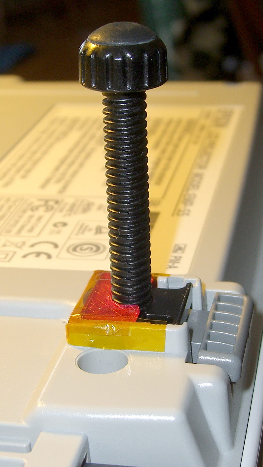
The third version snapped into place, with a square of tapeless sticky on the back to help keep it there. The obligatory Kapton tape helps retain it, but I have no illusions about the permanence of this repair:
Epson S5 Projector Foot – repair installed
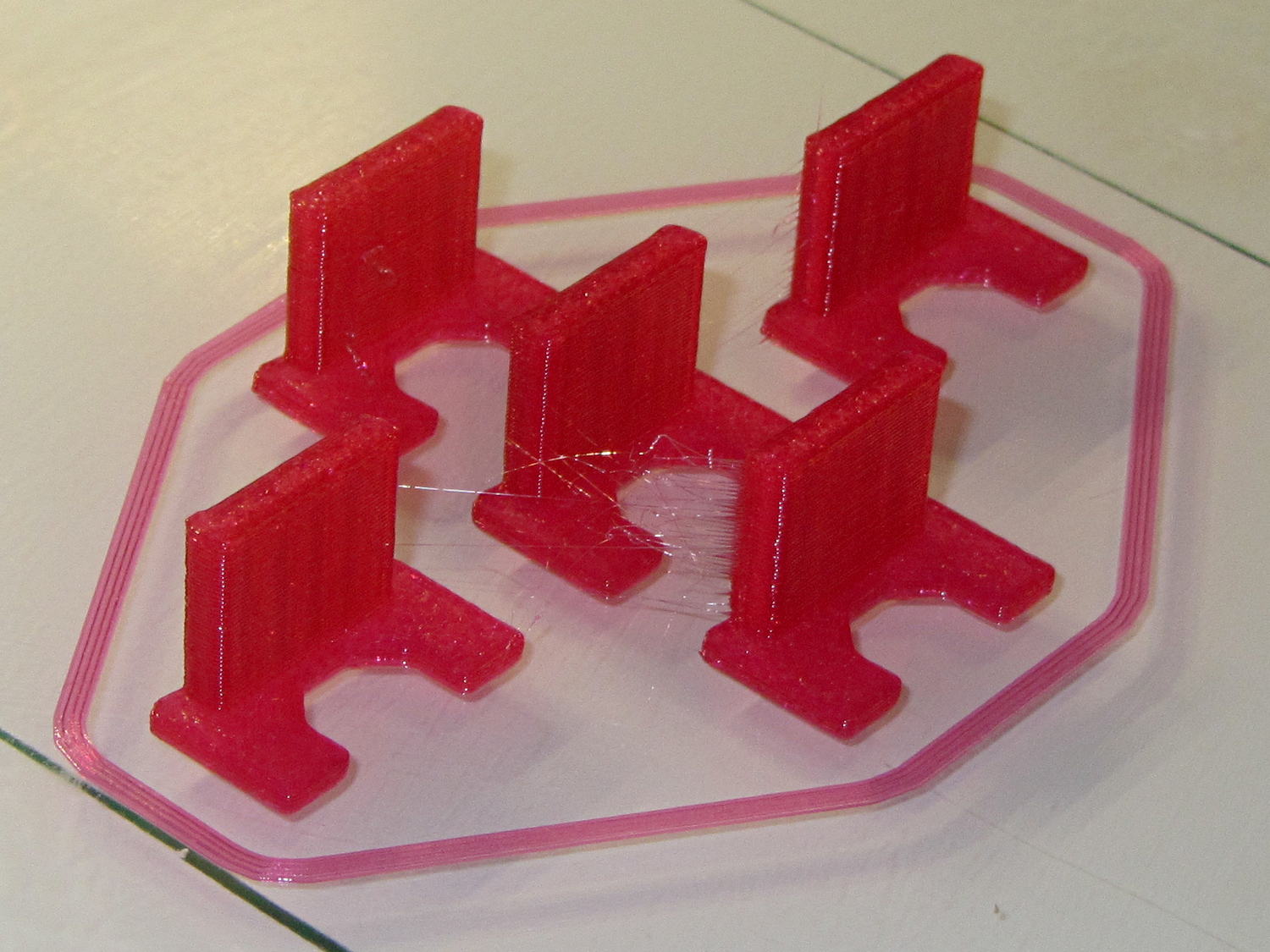
Because I know the problem will happen again, I called for backup:
Epson S5 Projector Foot – 5 copies
That’s with Hilbert Curve top / bottom fill, three top / bottom layers, 20% rectilinear infill, and two perimeters. Extruder at 250 °C, platform at 90 °C, hairspray for adhesion.
Note, however, the hair-fine strings connecting the towers. Retraction must be just about right, as shown by the overall quality of the objects, but PETG comes out really stringy. Choosing an infill pattern to minimize retraction seems like a big win; relatively sparse 3D Honeycomb works well on larger objects, but these were so small that straight line fill fit better. The flat plates on the bottom consist of five completely solid layers of PETG.
Reports from the field indicate complete success: whew!
One could, of course, just buy a replacement from the usual eBay supplier, if one were so inclined.