Ed Nisley's Blog: Shop notes, electronics, firmware, machinery, 3D printing, laser cuttery, and curiosities. Contents: 100% human thinking, 0% AI slop.
It seems all the drain boards under dish drainers are now intended for contemporary under-counter sinks without a rim, which is not the Old School drop-in sink we have in the kitchen. After considerable faffing about, I hacked a fix to make the drain board & drainer fit the sink:
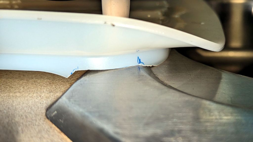
Dish Drainer – sink lip cutout
The crude notch not only lowers the front edge by a few millimeters, it also encourages the lip to stay over the sink, rather than sliding back over the counter and slobbering water everywhere.
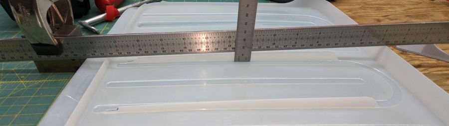
The drain board has stiffening ribs under the center section, cleverly arranged so they do not actually touch the counter. I measured the shape of the board near the ribs:
Dish Drainer – measuring center ribs
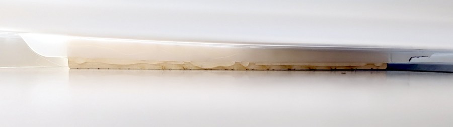
And then cut shapes to both support the board and rest on the counter:
Dish Drainer – center support
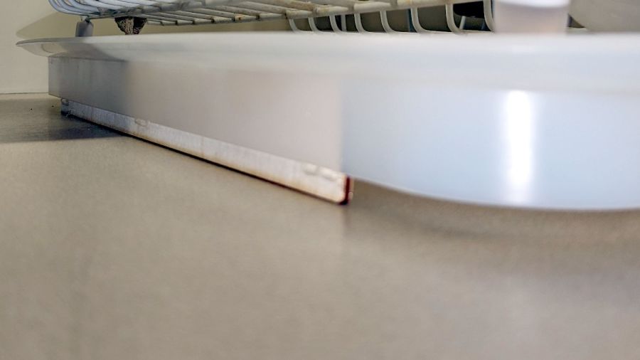
The board has a swale in the middle, directly over those ribs, requiring more tilt for proper drainage:
Dish Drainer – rear support
Getting all of that flying in formation required several iterations and we’re still not entirely satisfied, but at least the water flows into the sink and does not puddle in the drain board or on the counter.
Stipulated: wood is the wrong material for the job, hot melt glue is breathtakingly ugly, and you want no part of this.
The intended cuts are the dark lines, each with a poorly defined scorch 2 mm on its left. Knowing that the nozzle is about 4 mm, this suggests the beam is off-center enough to juuuust kiss the nozzle and splash the outer part of the beam away.
Having recently spot-checked the alignment and not seen any odd behavior on another platform-spanning project, this was puzzling. Given that the laser recently survived a move from one Basement Shop to another, with plenty of jostling while standing on end, I suppose I should have been more careful.
The biggest clue was seeing the shadow lines only near the front-right corner and noting they got worse farther into the corner. This seemed like the “fourth-corner” alignment problem described by St. Sadler some years ago and covered in a more succinct recent video.
AFAICT, the problem boils down to the difficulty of precisely aligning the beam at the longest distance it travels in the front-right corner. Careful adjustment of Mirror 1, after getting everything else lined up properly, seems to be solution.
The beam is slightly off-center at Mirror 1 and only a millimeter high on Mirror 2 at either end of the gantry travel along the Y axis.
The beam position at the laser head entry upstream of Mirror 3 shows the problem:
Beam Alignment – Initial M3 entry – 2024-05-31
The targets are left- and right-rear, left- and right-front, with varying pulse lengths obviously underpowering the last and most distant shot.
Looks like a classic fourth-corner problem!
Tweaking Mirror 1 by about 1/8 turn of the adjusting screw to angle the beam vertically upward eventually put the beam dead-center at Mirror 3:
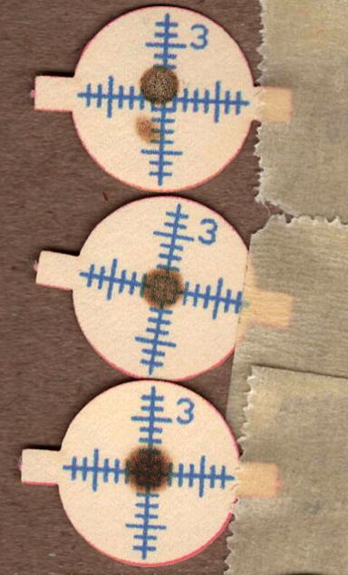
Beam Alignment – M3 adjustments – 2024-05-31
The bottom two targets are double pulses at the left- & right-rear and ‑front, so the beam is now well-centered.
A quick cross-check shows the beam remains centered on Mirror 2 at the front- and rear-end of the gantry travel, Mirror 3 is still OK, and the beam comes out of the center of the nozzle aperture:
Beam Alignment – M2 M3 exit final – 2024-05-31
Subsequent cutting proceeded perfectly all over the platform, so I think the alignment is now as good as it gets or, perhaps, as good as it needs to be.
Being in need of small bins to sort cutoffs / scrap material from the laser and now having an essentially unlimited supply of corrugated cardboard at hand, this made some sense:
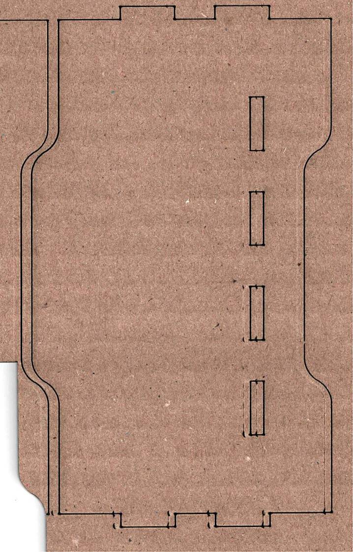
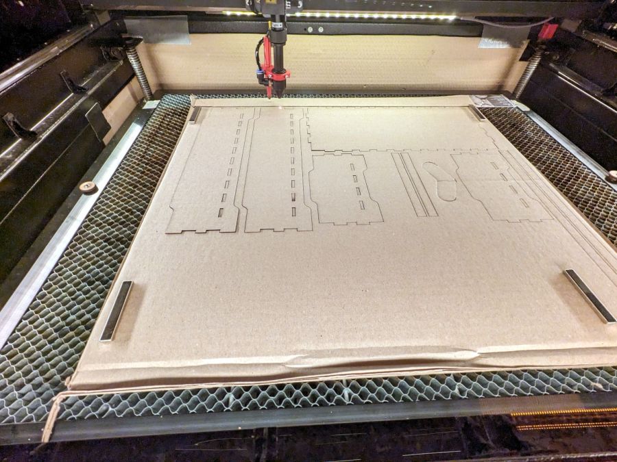
Laser scrap bins – cutting
The cardboard is 3.8 mm thick and laid with the ribs parallel to the X axis to make all the parts stiff in the right direction. I rearranged the parts to fit the space available and work around the butterfly finger hole over on the right.
Rather than gluing all those fingers into their holes, I ran a hot melt glue bead around the bottom perimeter and up the four corners, which seems to do the trick. The fingers parallel to the X axis tend to be fragile, as only one or two corrugated ribs run along their length, but the overall box is surprisingly rigid after gluing.
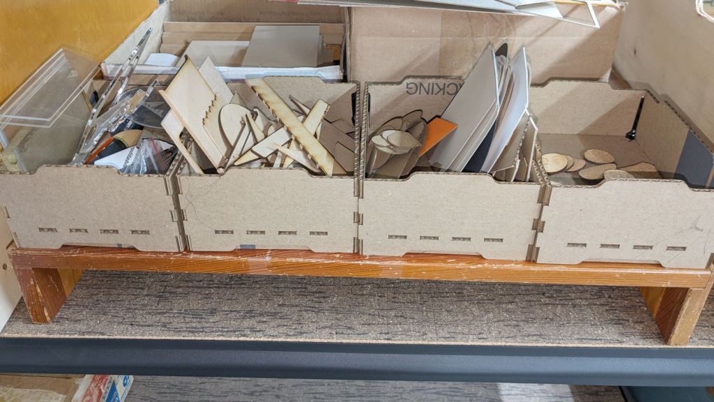
They’re nominally stackable and the pattern includes stiffeners glued across the leg openings so they don’t slide off the box below, but it’s obvious these boxes will always have too much stuff to allow stacking.
I made a longer box for plywood scraps and may need a couple more for other stuff yet to be unpacked, but you get the general idea.
The WordPress AI Assistant reminds me to remind you of the safety measures appropriate for using hot melt glue: consider yourself warned.
While setting up the small table I conjured from scrap, I discovered one of the folding legs no longer had a latch to keep it from folding. Whether it never had one or the latch got lost along the way, there’s no time like the present:
Table leg latch – installed
The bolt I put there in place of the joint rivet precludes a smaller latch along the lines of the simple steel loop on the other leg, so I figured I may as well go large and, with that much surface area, plywood will work just as well as steel for my simple needs.
When those set, I glued & clamped them together in situ, then wrapped the whole mess with what’s basically high-strength friction tape to encourage it to not come too far apart under the inevitable stress when the leg tries to fold with a pile of stuff on the table.
We’ll see how long this survives; if past experience is any guide, it’ll be a while.
The WordPress AI image generator has a shaky grasp of both human anatomy and the blog topic:
Woodwork design by Escher. What is that interesting tool? So many arms, all with nightmare fuel anatomy!
Long ago, I got Mary a cheap “desk calculator” with a vital function: it beeps cheerfully with each keypress. Nothing lasts forever and the aluminum dress panel around the keys has been gradually working its way loose.
So, we begin …
Gingerly remove the panel, un-bend and flatten it, lay it on the scanner, and cover with black paper:
C-Power calculator keyboard cover
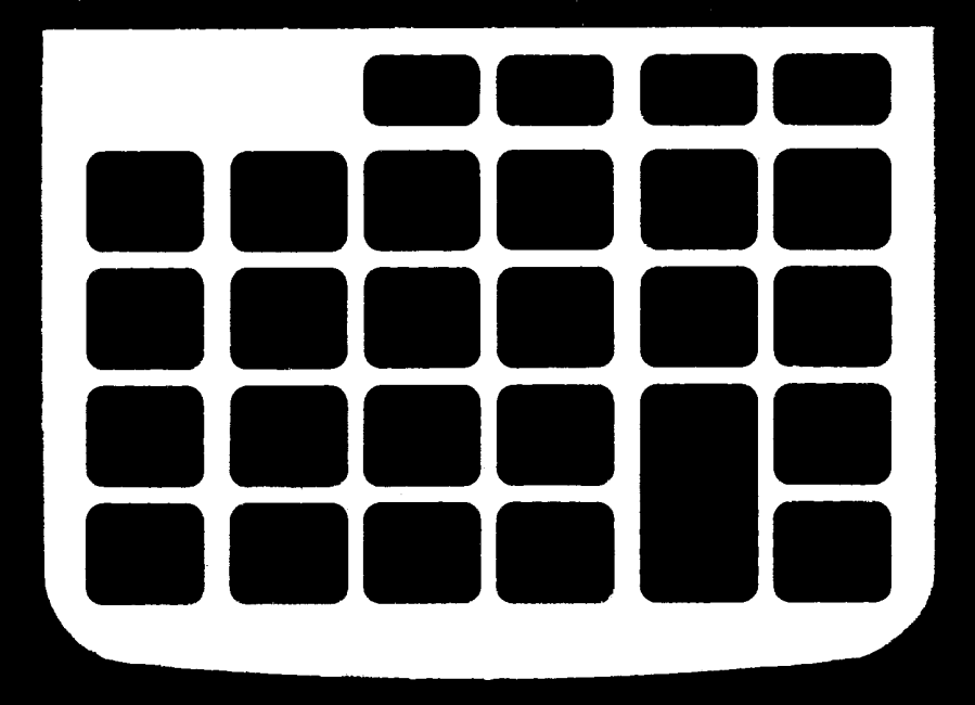
Blow out the contrast, threshold the image, do a little touchup, and get a binary mask:
C-Power calculator keyboard cover – mask
Import into LightBurn, trace and discard the image, do some shape optimization, add 0.2 mm to the height & width of one key, propagate those dimensions to other keys (Make same width and Make same height FTW), cut a paper prototype to verify the fit, iterate until it drops neatly into place, cut an adhesive sheet, then peel & stick:
C-Power KK-800A keyboard – adhesive placed
The dress panel was held in place by what was once a quick-setting gooey glue that had long since fossilized. Although it gave up on the aluminum, it was not going to come off the calculator body without more struggle than seemed warranted.
So I stuck the new glue atop the old glue and hoped for the best. You can see traces of the old glue bead through the sheet:
C-Power KK-800A keyboard – adhesive ready
Lay the dress panel in place, burnish between the rows & columns, and it looks about as good as it ever did:
C-Power KK-800A keyboard – restored
If the adhesive sheet also gives up on the aluminum, I’ll try some fancy 3M 300LSE adhesive.
The WordPress AI image generator heard I like keys, so it spat out some keys for my keyboards:
My ancient fluorescent magnifying desk lamp emerged from a box and cried out to be used, but the equally ancient 22 W fluorescent ring light was long past its prime and cried out to be replaced with something from the current millennium.
So I removed the fluorescent ballast / choke from the junction box at the lamp base:
Magnifying Ring Light – ballast removed
That’s a grounded outlet in the cover plate serving as a wire termination block. The red crimp connector joins a white wire that formerly went to the ballast with the black wire going to the lamp head; you’ll note the black wire from the line cord going into the same heatstink tubing at the outlet.
The lamp head had a push-to-start switch, presumably with an internal starting capacitor or some such, but also sporting a pair of terminals behaving like a single-pole push-on / push-off switch. A bit of rewiring, of which there are no pictures, made it work perfectly with the new 13 W LED ring light:
Magnifying Ring Light – LED ring installed
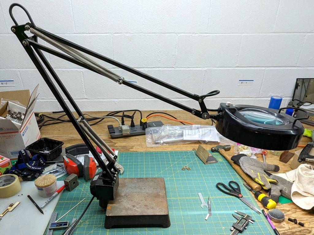
It now sits on a bit of laboratory ironmongery weighing about as much as a small child:
Magnifying Ring Light – on base
Although the base has four feet, it sits perfectly flat on my (admittedly battered) surface plate because all four feet have been ground to make that happen:
Magnifying Ring Light – foot plan view
Those feet will be hostile to any table / bench top outside their intended laboratory environment. Fortunately, the geometry is simple enough to build directly in LightBurn and cut from a cork disk with PSA backing suited to become a coaster:
Magnifying Ring Light – cork foot cutting
Which fit well enough, although all four feet are just slightly different:
Magnifying Ring Light – cork foot
The new Basement Shop™ is coming together and this stuff is getting easier …
The WordPress AI came up with a plausible steampunk build:
Magnifying Ring Light – WP AI image 1
Love those flowy feet, although the vertical rod in the back seems misplaced.
Adding “one-piece base” to the prompt produces contemporary style:
Magnifying Ring Light – WP AI image 2
Dunno what the dingus on the lower arm might be (perhaps a spring?), but it’s got the right general idea.
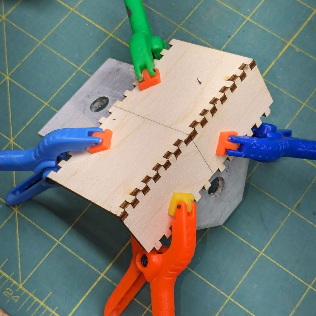
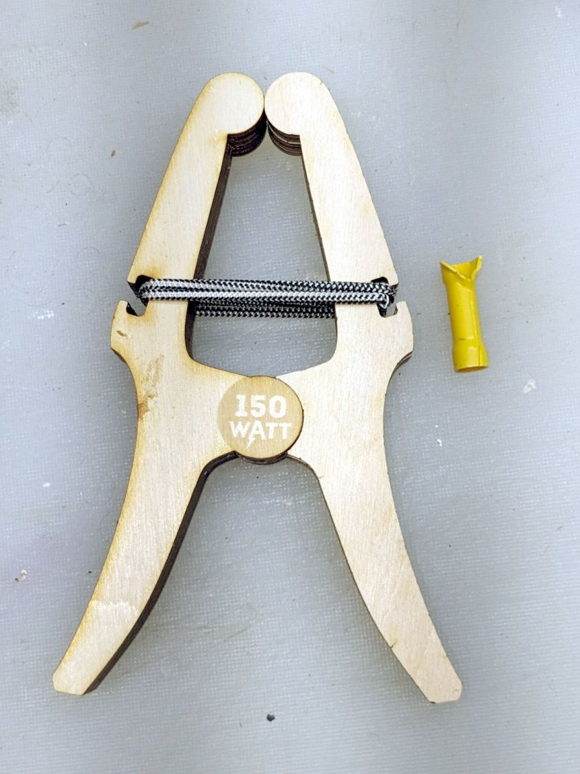
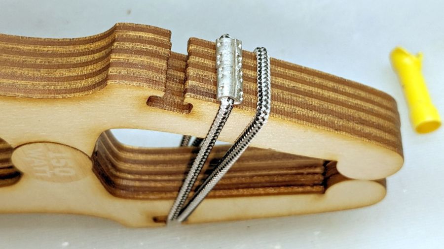
The original gets its clamping force from a gazillion rubber bands, but two wraps of shock cord joined by the guts of an electrical crimp connector worked for my simple needs:
Plywood clamp – shock cord crimp connector
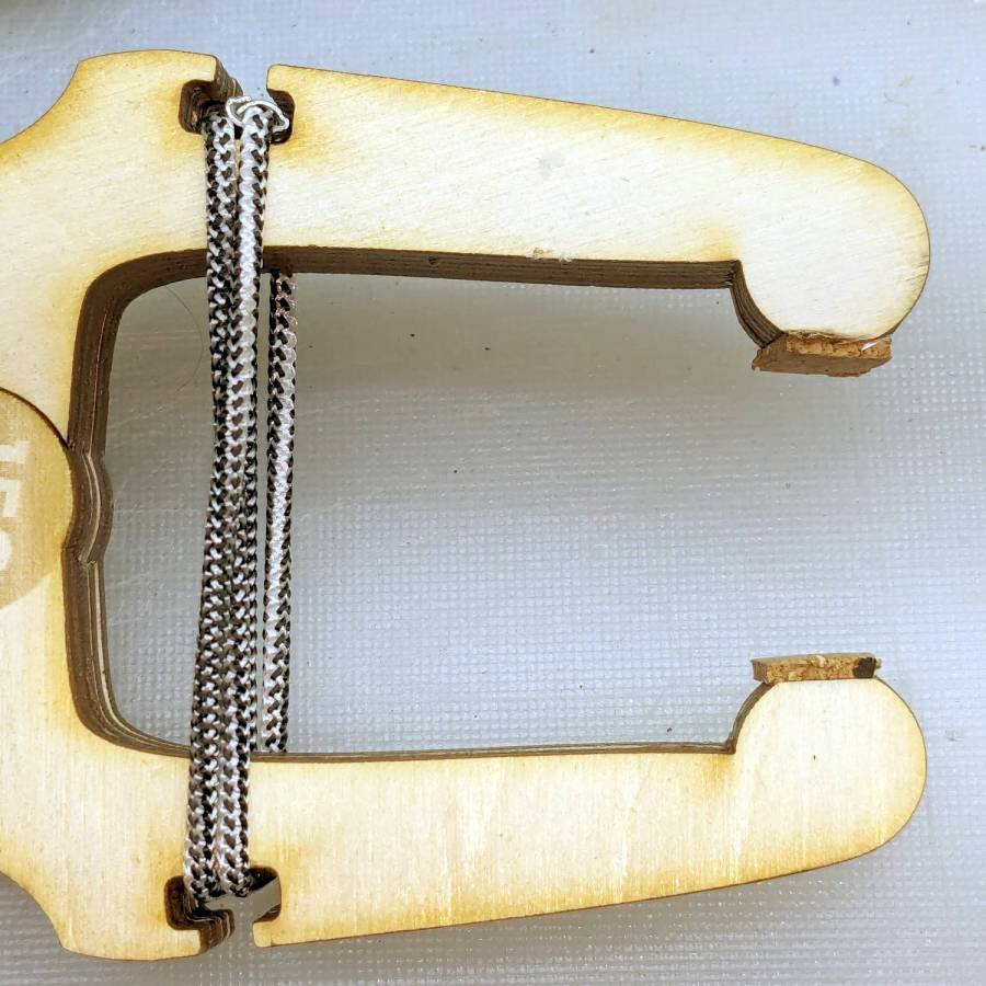
The rounded tips work at any thickness, but introducing them to Ms Belt Sander set them for the specific purpose I have in mind:
Plywood clamp – flatted tips
The little cork pads are hand-cut from scraps, because why not.
Rubbing paraffin (wax, not kerosene) on the circular joint’s bearing surfaces makes the hinge move soooo smoothly.
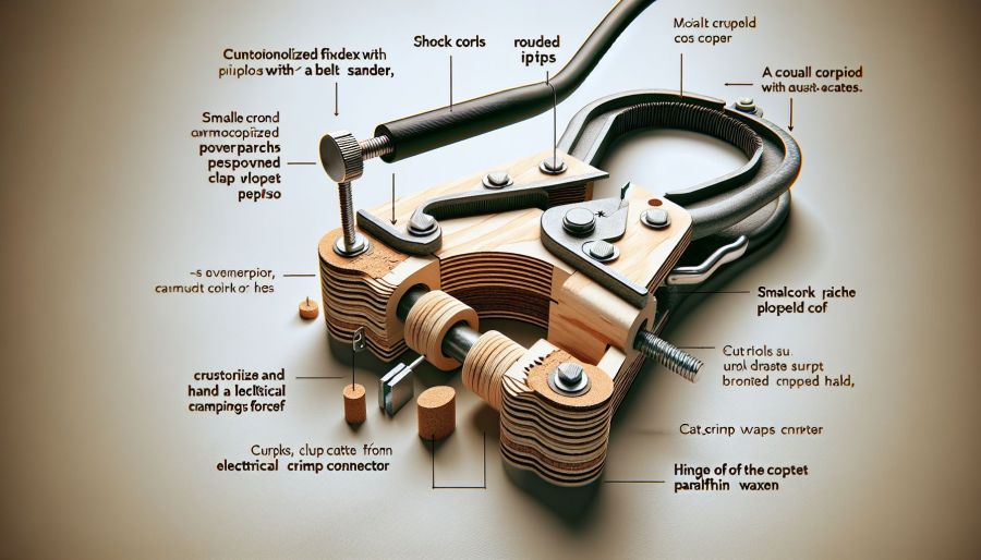
The WordPress AI image generator is trying much harder:
Plywood clamp – WP AI Image
The callouts almost make sense, because they’re now ripped from the post text. For sure, I will “crustorilize” my next shop project.
Gotta love the AI evaluation:
The content shows a practical and creative approach to making a plywood clamp, supported by clear images. Consider adding a brief introduction to provide context for the project. Additionally, explaining the specific purpose for which the clamp is intended would further engage readers. The use of humor and informal language adds a personal touch, enhancing the connection with the audience. Overall, the engaging content and visual aids make it a compelling read.


