Ed Nisley's Blog: Shop notes, electronics, firmware, machinery, 3D printing, laser cuttery, and curiosities. Contents: 100% human thinking, 0% AI slop.
Which turned out to be entirely too stiff, which wasn’t surprising given that Trolase Thin is intended for signage stuck on flat or slightly curved surfaces.
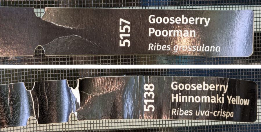
Despite being “paper”, laser testing paper is also too stiff:
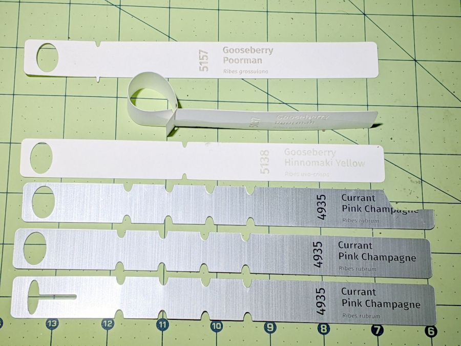
Laser test paper – outdoor labels – 2024-06-22
The wrinkles and cracks on the left end of the tags shows the plastic coating makes it basically impossible to shape / bend the paper enough to wrap around a plant stem, then push it through the hole (offscreen to the left). I was not surprised too much by this discovery.
Those two strips now hang outside the kitchen window (left end upward), where they’ll get enough sun and rain to keep a plant happy, and I’ll see how well the engraved / damaged plastic coating stands up to that sort of abuse.
While setting up to drill holes in the aluminum base for the running light buck converter, I wondered if laser-marking the spots directly from the solid model would work better than my usual fumbling around.
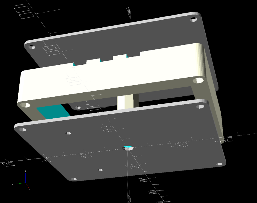
The solid model:
Running Light – power box – bottom view
Export projections of the pieces from OpenSCAD as an SVG file:
Running Light – power box – Projection view
Import into LightBurn, set up for a very fast, very light cut and Fire The Laser:
Laser-marked hole spots – masking tape
That’s in ordinary masking tape on a hard-anodized sheet of aluminum from the pile, which looked better than I expected.
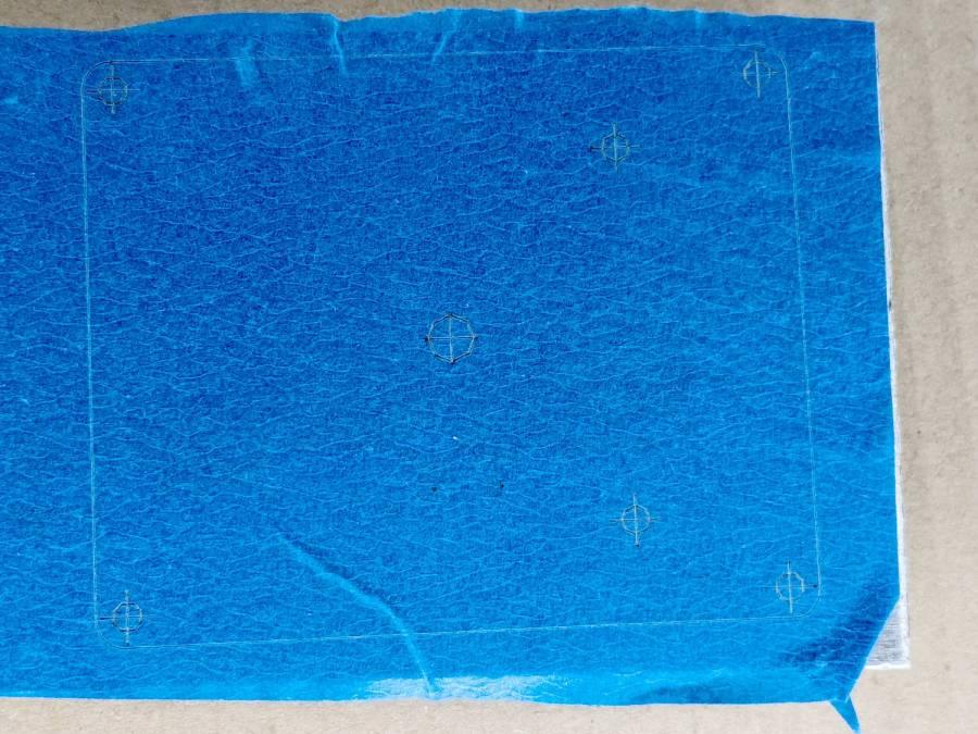
The same aluminum covered with blue tape:
Laser-marked hole spots – blue tape – hard anodize
Which looks much better in person than it does in the photo.
On a soft aluminum sheet from the Basement Warehouse Zone:
Laser-marked hole spots – blue tape – sheet aluminum
The dark outline is a comfort mark hand-drawn around a chipboard test piece to verify the layout fit between random holes drilled in the sheet during its previous life.
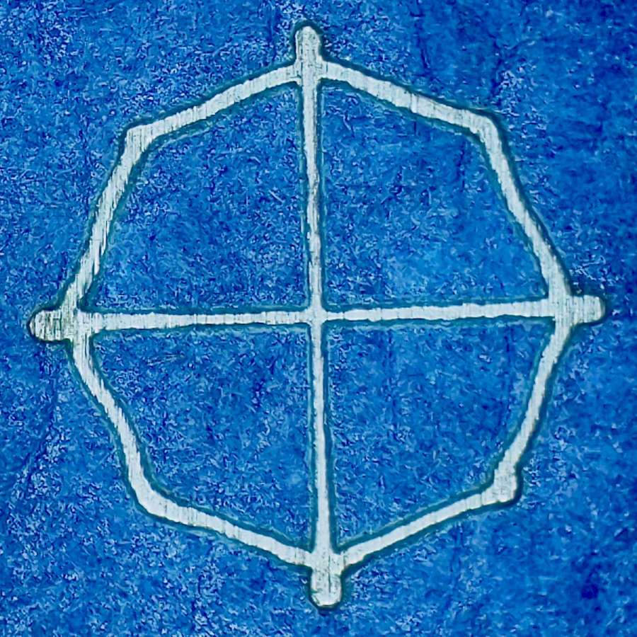
A closer look at a corner hole:
Laser-marked hole spots – blue tape – hard anodize – detail 1
And the center hole:
Laser-marked hole spots – blue tape – hard anodize – detail 2
The holes appeared in the right places after center-punching by eye, but the fragility of those four little tape leaves around the center point must be experienced to be believed.
And, yes, those are deliberately low-polygon approximations to a circle, because I’m a low-poly kind of guy.
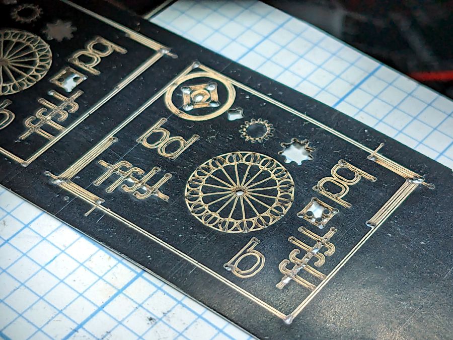
That’s the standard backlash test pattern shrunken down to a little over an inch wide, with the laser power reduced to the bare minimum. Despite that, the numerous holes show where the pattern concentrates enough energy to vaporize the paper.
The “paper” seems to be laminated between two black plastic sheets that smell terrible when engraved, so they’re probably some form of acrylic. The Amazon product description is, despite all the verbiage- remarkably uncommunicative of the actual materials involved.
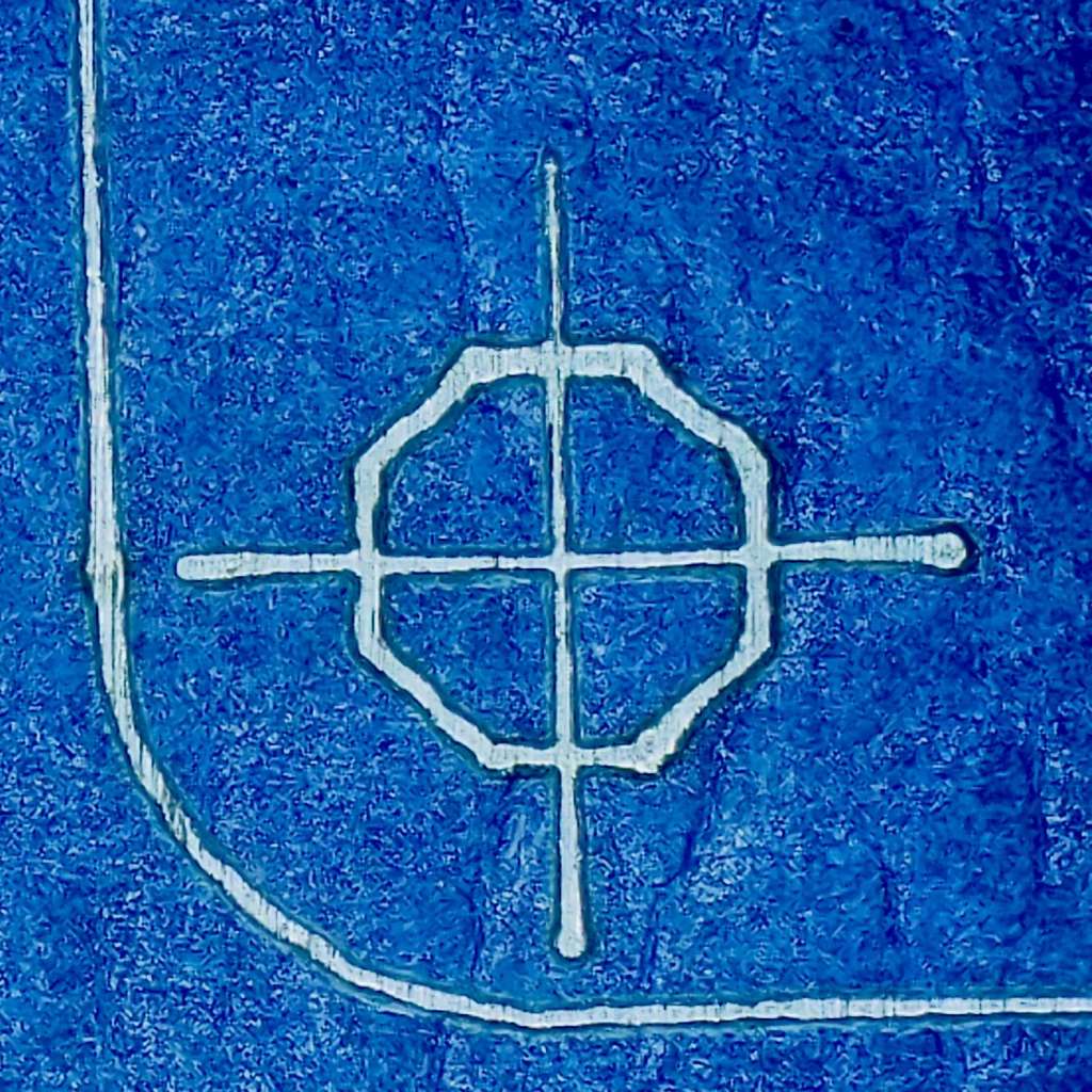
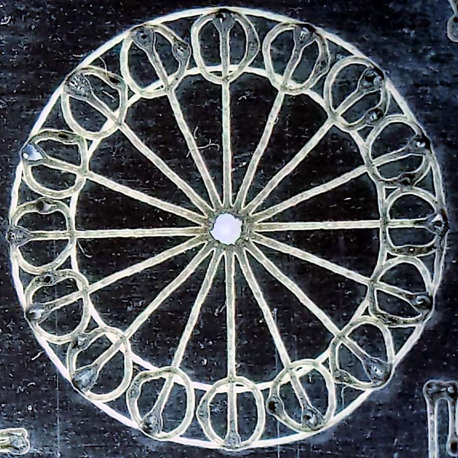
The circular pattern is 10 mm diameter on the outside:
Laser test paper – miniature pattern detail
Those should be circles around the perimeter, but their distortion shows what happens when you try to move a hulking CO₂ laser head around a 1.5 mm diameter circle at 400 mm/s. Of course, the actual speed is nowhere near that fast along such tiny vectors.
The traces are about 0.2 mm wide, with obvious scorches where the beam starts and stops, which agrees reasonably well with previousmeasurements.
All in all, both the paper and the laser pattern look better than I expected, particularly as the results indicate the machine has no measurable backlash at all.
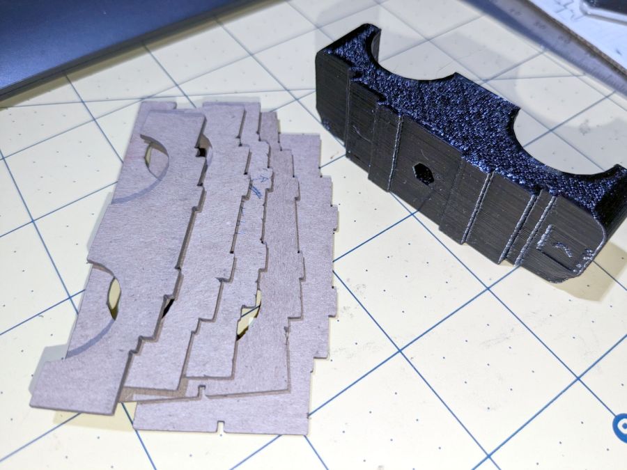
The top profile fits snugly into the battery mounting plate, with clearance on the sides for the latches:
UPP Battery Mount – trial fit
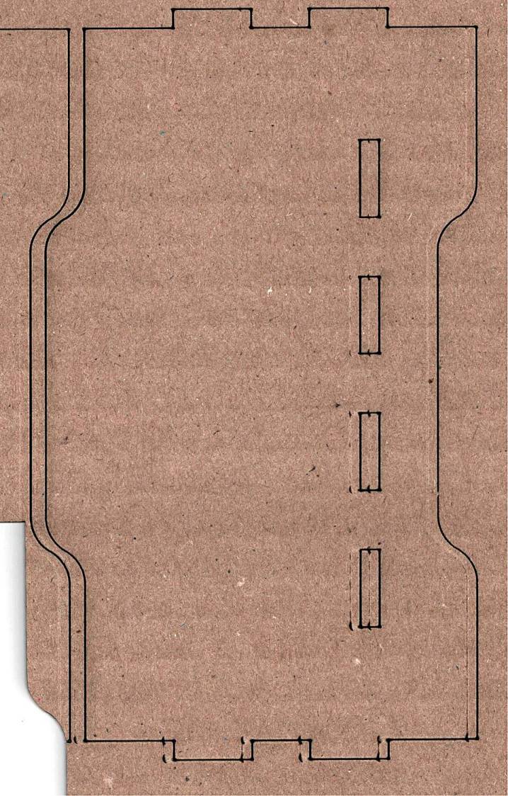
However, I had enough trouble measuring those recesses that I broke down and added a projection() view to the OpenSCAD code:
UPP Battery Mount – profile
Exporting that as an SVG image and importing it into LightBurn let me cut it out of chipboard:
UPP Battery Mount – laser cut profiles
Obviously, it took several iterations to fit the top profile to the baseplate, particularly after finding slightly different measurements at each block position. On the other paw, laser cutting the profiles proceeded much more quickly than 3D printing just a few millimeters of the block, so it was a net win.
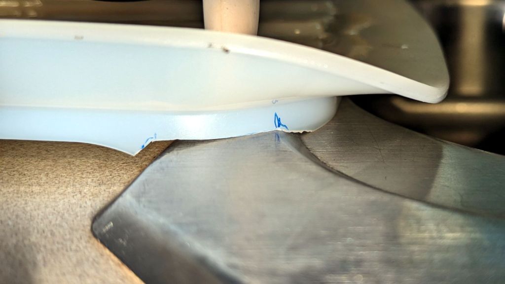
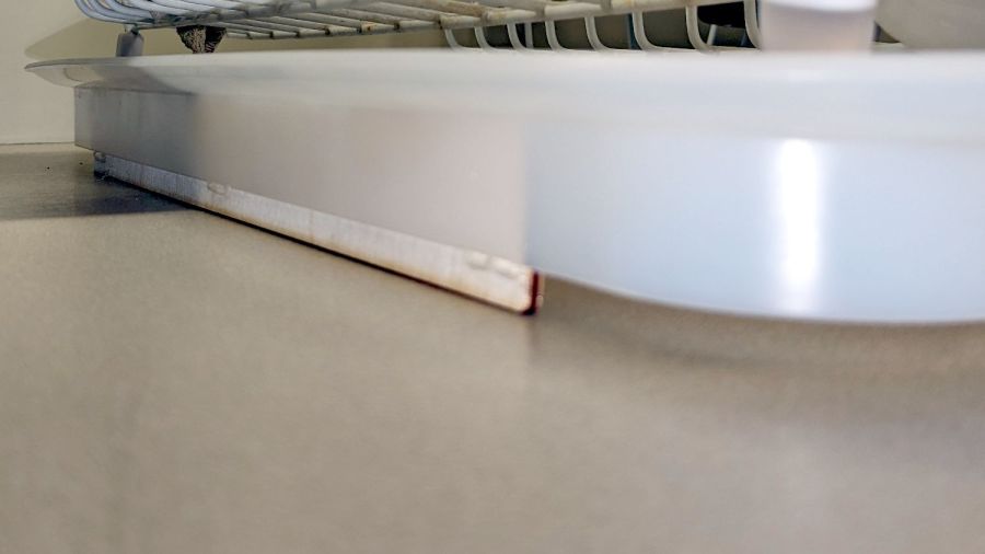
It seems all the drain boards under dish drainers are now intended for contemporary under-counter sinks without a rim, which is not the Old School drop-in sink we have in the kitchen. After considerable faffing about, I hacked a fix to make the drain board & drainer fit the sink:
Dish Drainer – sink lip cutout
The crude notch not only lowers the front edge by a few millimeters, it also encourages the lip to stay over the sink, rather than sliding back over the counter and slobbering water everywhere.
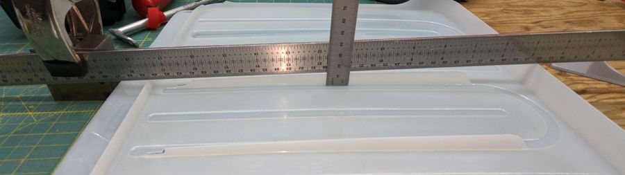
The drain board has stiffening ribs under the center section, cleverly arranged so they do not actually touch the counter. I measured the shape of the board near the ribs:
Dish Drainer – measuring center ribs
And then cut shapes to both support the board and rest on the counter:
Dish Drainer – center support
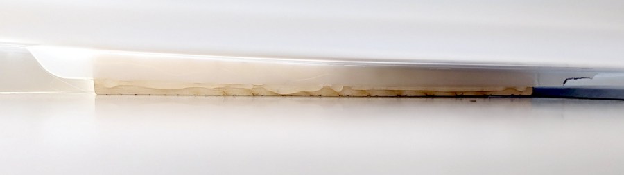
The board has a swale in the middle, directly over those ribs, requiring more tilt for proper drainage:
Dish Drainer – rear support
Getting all of that flying in formation required several iterations and we’re still not entirely satisfied, but at least the water flows into the sink and does not puddle in the drain board or on the counter.
Stipulated: wood is the wrong material for the job, hot melt glue is breathtakingly ugly, and you want no part of this.
The intended cuts are the dark lines, each with a poorly defined scorch 2 mm on its left. Knowing that the nozzle is about 4 mm, this suggests the beam is off-center enough to juuuust kiss the nozzle and splash the outer part of the beam away.
Having recently spot-checked the alignment and not seen any odd behavior on another platform-spanning project, this was puzzling. Given that the laser recently survived a move from one Basement Shop to another, with plenty of jostling while standing on end, I suppose I should have been more careful.
The biggest clue was seeing the shadow lines only near the front-right corner and noting they got worse farther into the corner. This seemed like the “fourth-corner” alignment problem described by St. Sadler some years ago and covered in a more succinct recent video.
AFAICT, the problem boils down to the difficulty of precisely aligning the beam at the longest distance it travels in the front-right corner. Careful adjustment of Mirror 1, after getting everything else lined up properly, seems to be solution.
The beam is slightly off-center at Mirror 1 and only a millimeter high on Mirror 2 at either end of the gantry travel along the Y axis.
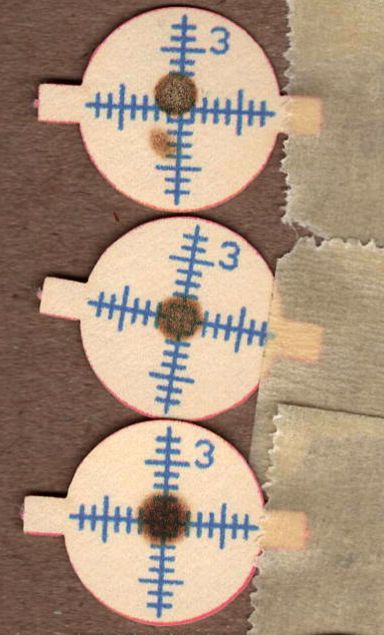
The beam position at the laser head entry upstream of Mirror 3 shows the problem:
Beam Alignment – Initial M3 entry – 2024-05-31
The targets are left- and right-rear, left- and right-front, with varying pulse lengths obviously underpowering the last and most distant shot.
Looks like a classic fourth-corner problem!
Tweaking Mirror 1 by about 1/8 turn of the adjusting screw to angle the beam vertically upward eventually put the beam dead-center at Mirror 3:
Beam Alignment – M3 adjustments – 2024-05-31
The bottom two targets are double pulses at the left- & right-rear and ‑front, so the beam is now well-centered.
A quick cross-check shows the beam remains centered on Mirror 2 at the front- and rear-end of the gantry travel, Mirror 3 is still OK, and the beam comes out of the center of the nozzle aperture:
Beam Alignment – M2 M3 exit final – 2024-05-31
Subsequent cutting proceeded perfectly all over the platform, so I think the alignment is now as good as it gets or, perhaps, as good as it needs to be.
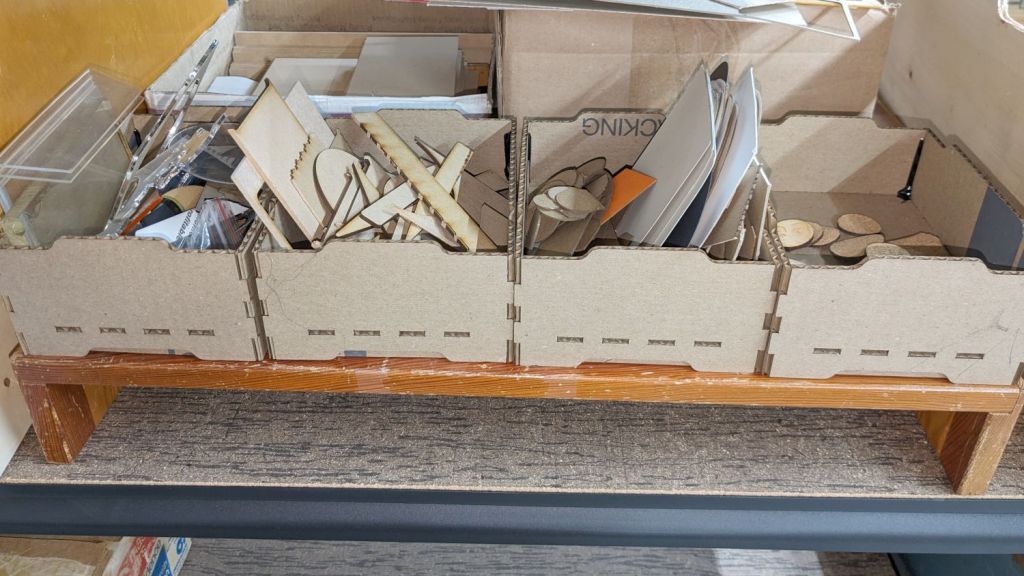
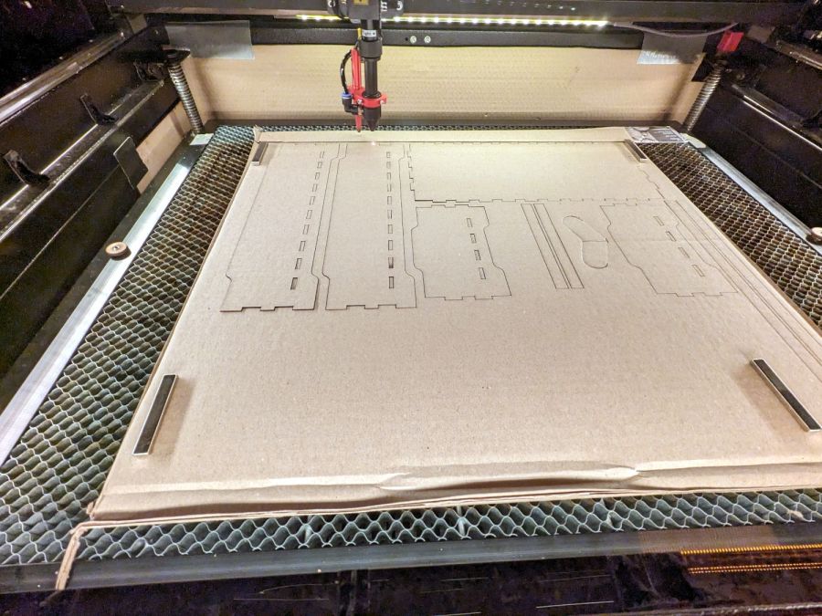
Being in need of small bins to sort cutoffs / scrap material from the laser and now having an essentially unlimited supply of corrugated cardboard at hand, this made some sense:
Laser scrap bins – cutting
The cardboard is 3.8 mm thick and laid with the ribs parallel to the X axis to make all the parts stiff in the right direction. I rearranged the parts to fit the space available and work around the butterfly finger hole over on the right.
Rather than gluing all those fingers into their holes, I ran a hot melt glue bead around the bottom perimeter and up the four corners, which seems to do the trick. The fingers parallel to the X axis tend to be fragile, as only one or two corrugated ribs run along their length, but the overall box is surprisingly rigid after gluing.
They’re nominally stackable and the pattern includes stiffeners glued across the leg openings so they don’t slide off the box below, but it’s obvious these boxes will always have too much stuff to allow stacking.
I made a longer box for plywood scraps and may need a couple more for other stuff yet to be unpacked, but you get the general idea.
The WordPress AI Assistant reminds me to remind you of the safety measures appropriate for using hot melt glue: consider yourself warned.