The Smell of Molten Projects in the Morning

Ed Nisley's Blog: Shop notes, electronics, firmware, machinery, 3D printing, laser cuttery, and curiosities. Contents: 100% human thinking, 0% AI slop.

Tag: Laser Cutter

  • DVD Coasters: Stress Cracking

    DVD Coasters: Stress Cracking

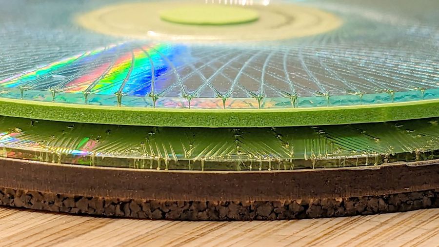
    A bit less than a year ago I engraved Guilloche patterns on a stack of DVDs, stuck foam on their data sides, and defined the result to be coasters:

    Laser cut CDs - Foam vs MDF-cork backing - detail
    Laser cut CDs – Foam vs MDF-cork backing – detail

    Perhaps unsurprisingly, those grooves turned out to be excellent stress raisers, to the extent that the two most-used coasters (we’re not talking heavy use) have developed cracks:

    Laser-engraved DVD A - stress cracks
    Laser-engraved DVD A – stress cracks

    The parallel lines are part of the logo / pattern / design printed on the label side of the disc, which seems to have wrinkled after being glued to the foam layer. The cracks radiate outward from the laser-scarred zone around the hub.

    The other one is worse:

    Laser-engraved DVD B - stress cracks
    Laser-engraved DVD B – stress cracks

    None of the discs glued to rigid backing plates show anything more than minor cracks, so I think a combination of stress raising and slight flexing is really bad for cheap coaster-like objects.

    No great loss, easily outweighed by knowing what not to do next time …

  • MMU3 vs. Cart Coin Calibrators

    MMU3 vs. Cart Coin Calibrators

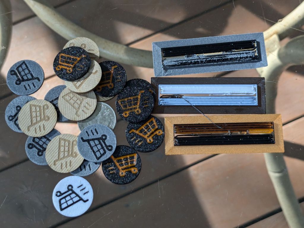
    The last time around, I used Cart Coins to verify platform alignment (a.k.a. “leveling”) on the Makergear M2. The Prusa MK4 does mesh probing to ensure accurate alignment, so these new Cart Coins exercised the MMU3 and gave me some giveaways for a recent dinner:

    Cart Coin - assortment
    Cart Coin – assortment

    The design, such as it is, mashes a PNG found on the InterWebs with a few go-fast stripes added in LightBurn to balance the layout inside a circle:

    Cart Coin layout
    Cart Coin layout

    The motivations for LightBurn:

    • It’s convenient
    • TroCraft Eco is within 0.1 mm of the proper thickness
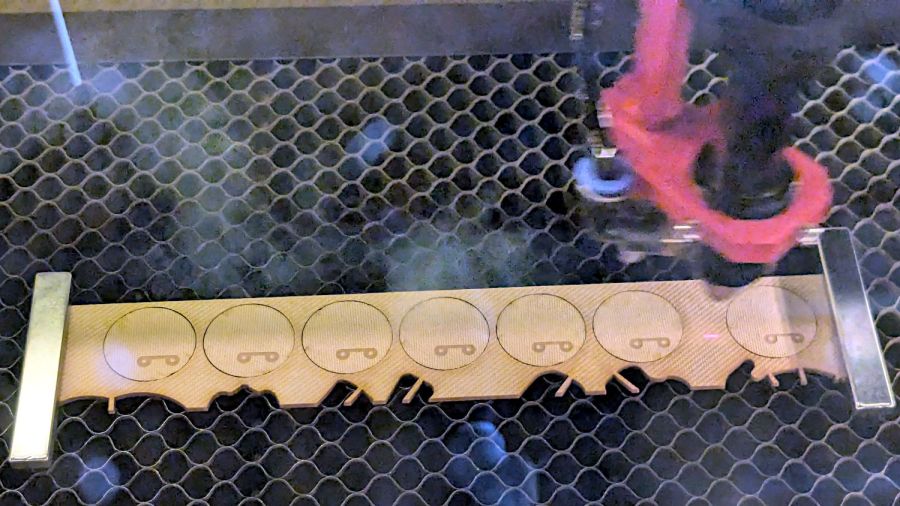
    • Laser-cut coins proceed with great speed

    Normally you’d export the finished layout as an SVG, but OpenSCAD ignores “holes” within shapes, so I exported it as a PNG to serve as a binary height map:

    • Import the PNG into OpenSCAD using surface()
    • Resize it to 20 mm wide and 1.7 mm tall
    • Knock it out of a 24 mm OD × 1.6 mm tall cylinder (which is why the extra 0.1 mm)
    • Add the PNG again as a separate 1.6 mm object to refill the hole

    Whereupon out pops a solid model:

    Cart Coin - solid model
    Cart Coin – solid model

    Export that as a 3mf file to keep the two objects aligned, import it into PrusaSlicer, then get multi-material on it:

    Cart Coin - PrusaSlicer layout
    Cart Coin – PrusaSlicer layout

    There’s a fourth group with different colors in hiding. I printed 12 identical coins at a time, mostly so I could keep track of what was happening, and it ended well enough.

    The black coins with the translucent retina-burn orange cart look surprisingly good.

    But this is way faster:

    They’re the size of a US quarter, because that’s what unlocks shopping carts around here. Feel free to tweak the parameters for your locale.

    The OpenSCAD source code is almost a one-liner:

    difference() {
        cylinder(d=24.0,h=1.6);
    
        resize([20.0,0,1.7],auto=true)
            linear_extrude(height=1,convexity=10)
               projection(cut=true)
                surface("/mnt/bulkdata/Project Files/Prusa Mk4/Models/Cart Coin/Cart Coin layout.png",
                        center=true,invert=true);
    }
    
        color("Black")
            resize([20.0,0,1.6],auto=true)
                linear_extrude(height=1,convexity=10)
                   projection(cut=true)
                    surface("/mnt/bulkdata/Project Files/Prusa Mk4/Models/Cart Coin/Cart Coin layout.png",
                            center=true,invert=true);
    

    Use them responsibly, OK?

  • Prusa MK4 Y Motor Shim

    Prusa MK4 Y Motor Shim

    Having been viciously nerd-sniped by The Great Dragorn of Kismet, I’m in the process of building a Prusa MK4 3D printer with an MMU3. This has been a generally pleasant experience, although I am beginning to loathe Genuine Haribo Goldbären.

    Anyhow, the Y axis motor position puts the belt too close to one side of the pulley, with no further adjustment possible:

    Prusa MK4 Y axis motor mount - as-built
    Prusa MK4 Y axis motor mount – as-built

    The stepper motor stator laminations are the striped gray area on the far left, the 3D printed motor mount is the striped black area on the right, and the belt pulley is snugged up against the motor as far as it can go on the shaft.

    Pushing the motor a little more to the left requires a shim:

    Prusa MK4 Y axis motor mount - shim
    Prusa MK4 Y axis motor mount – shim

    Rather than fiddle with scanning the motor mount, I imported its STL model from the Prusa MK4 files:

    Prusa MK4 Y Axis Motor mount - solid model
    Prusa MK4 Y Axis Motor mount – solid model

    Importing the STL into OpenSCAD and converting the motor face into an SVG file is basically a one-liner:

    projection(cut=true)
    translate([0,0,-5.0])
    import("/mnt/bulkdata/Project Files/Prusa Mk4/Calibration/y_motor_holder_R3.stl");
    

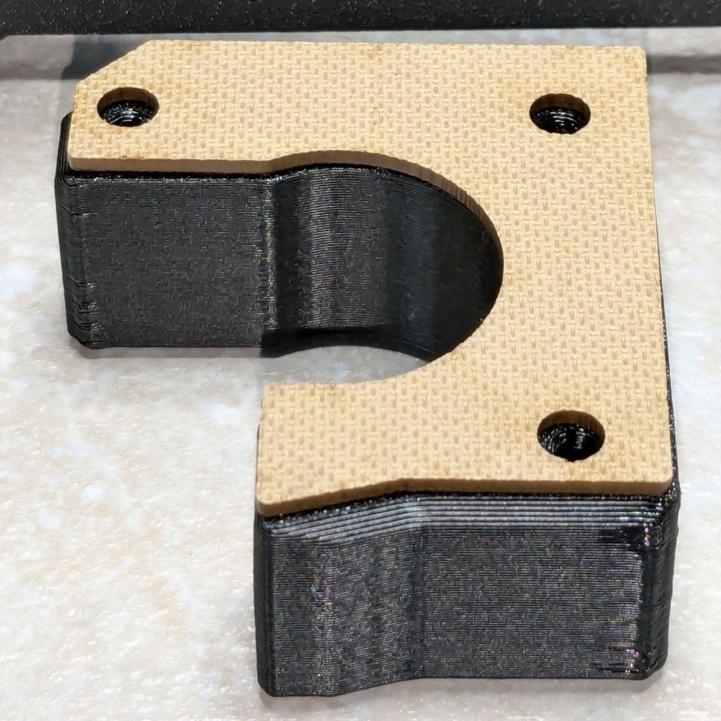
    Import the SVG into LightBurn, round the corners a little, set it up for 1.5 mm Trocraft Eco, Fire. The. Laser. and it fits perfectly and stands out nicely:

    Prusa MK4 Y axis motor mount - shimmed
    Prusa MK4 Y axis motor mount – shimmed

    Having the right tools for a job makes it easy …

  • Laser-cut Paper Pad Hooks

    Laser-cut Paper Pad Hooks

    Mostly because I could:

    Laser-cut MDF paper hooks
    Laser-cut MDF paper hooks

    Another pair of hooks support the far end of the sketch paper pad, all hanging on the end of the shelves holding laser materials & tooling.

    MDF isn’t particularly well-suited as a hook for anything weighing more than a dozen sheets of paper, but that pad is now out of the way where it won’t get curled.

    The shape comes from a bunch of rectangles welded together in LightBurn, with the obvious corners rounded off for stylin’.

  • Glass-top Patio Table Leg Brackets: Hardfought

    Glass-top Patio Table Leg Brackets: Hardfought

    A glass-top patio table came with our house and, similar to one of the patio chairs, required some repair. The arched steel legs fit into plastic brackets / sockets around the steel table rim under the glass top:

    Glass patio table - new brackets installed
    Glass patio table – new brackets installed

    The four glaringly obvious white blocks are the new brackets.

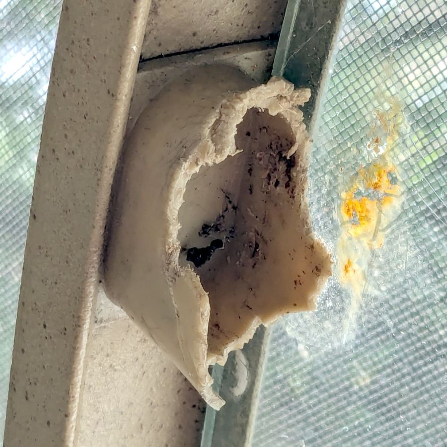
    The original brackets had, over uncounted years, deteriorated:

    Glass patio table - failed OEM bracket
    Glass patio table – failed OEM bracket

    Perhaps disintegrated would be a better description:

    Glass patio table - crumbled OEM bracket
    Glass patio table – crumbled OEM bracket

    Each leg has a pair of rusted 1-½ inch ¼-20 screws holding it to the central ring. As expected, seven of the eight screws came out easily enough, with the last one requiring an overnight soak in Kroil penetrating oil plus percussive persuasion:

    Glass patio table - jammed screw
    Glass patio table – jammed screw

    The four legs had three different screws holding them to the brackets, so I drilled out the holes and squished M5 rivnuts in place:

    Glass patio table - M5 rivnut installed
    Glass patio table – M5 rivnut installed

    Although it’s not obvious, the end of that tube is beveled with respect to the centerline to put both the top and bottom edges on the table rim inside the bracket. In addition, the tube angles about 10° downward from horizontal, which I did not realize amid the wrecked fittings, so the first bracket model failed instantly as I inserted the leg:

    Glass patio table - first bracket test
    Glass patio table – first bracket test

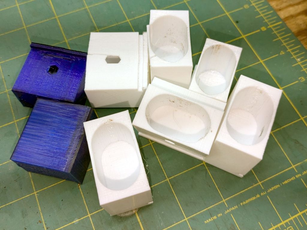
    The top & bottom walls of that poor thing were breathtakingly thin (to match the original bracket) and cracked when confronted with the angled tube. I could not measure all the sizes & angles without assembling the table on trial brackets, so getting it right required considerable rapid prototyping:

    Glass patio table - failed brackets
    Glass patio table – failed brackets

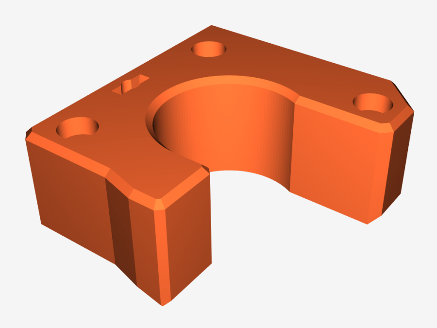
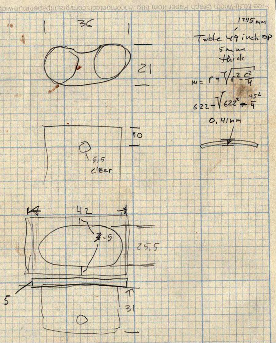
    Some trigonometry produced a solid model with features rebuilding themselves around the various sizes / angles / offsets:

    Glass Top Table - leg bracket - solid model
    Glass Top Table – leg bracket – solid model

    A sectioned view shows the angled tube position and end chamfer:

    Glass Top Table - leg bracket - section view
    Glass Top Table – leg bracket – section view

    The OpenSCAD code can produce a sectioned midline slice useful for laser-cut MDF pieces to check the angle:

    Glass patio table - chunky bracket installed - bottom
    Glass patio table – chunky bracket installed – bottom

    That eliminated several bad ideas & misconceptions, although trying to balance the leg on a 3 mm MDF snippet was trickier than I expected. In retrospect, gluing a few snippets together would be easier and still faster than trying to print a similar section from the model.

    The slightly elongated slot for the M5 screw shows that the original screw holes were not precisely placed or that the tubes were not precisely cut, neither of which come as a surprise. I finally built some slop into the design to eliminate the need for four different blocks keyed to four different legs.

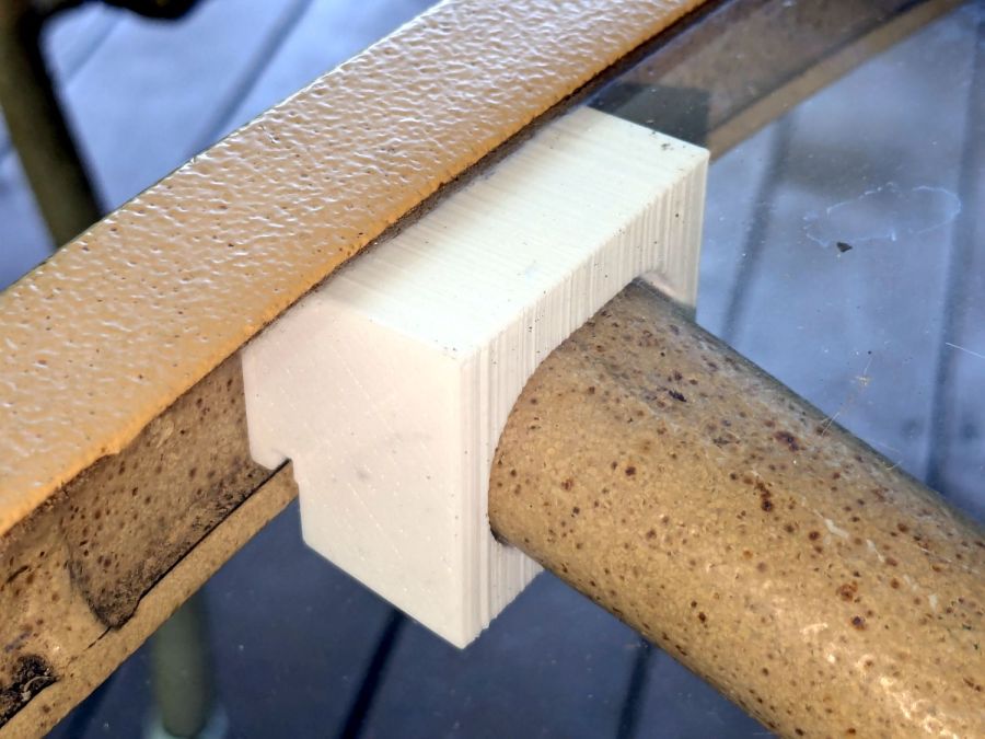
    The outer rim, the notch on the bottom, and the tab on the top curve to match the four foot OD glass tabletop, with the inward side & ends remaining flat:

    Glass patio table - chunky bracket installed - top
    Glass patio table – chunky bracket installed – top

    The sector’s difference from a straight line amounts to half a millimeter and improved the fit enough to justify the geometric exercise. The bracket snaps into position with the notch over the table rim and the tab locked in the gap between the glass disk & the rim, although I suspect the weight of the tabletop would keep everything aligned anyway.

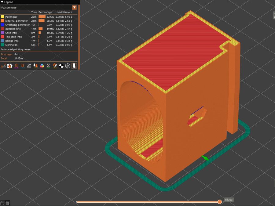
    The walls are now at least 4 mm thick and, printed in PETG, came out strong enough to survive assembly and some gentle testing. They’re arranged to print on their side to eliminate support under those slight curves and to align the layers for best strength vertically in the finished bracket:

    Glass Top Table - leg bracket - slicer preview
    Glass Top Table – leg bracket – slicer preview

    The leg cavity and screw hole built well enough without internal support.

    They’re relentlessly rectangular and I’m not going to apologize one little bit.

    Now to see how they survive out there on the screened porch.

    The OpenSCAD source code as a GitHub Gist:

    // Glass patio table leg brackets
    // Ed Nisley – KE4ZNU
    // 2024-08
    /* [Layout] */
    Layout = "Show"; // [Section,Projection,Show,Build]
    Part = "Leg"; // [Leg, RimPlate, Block, Bracket]
    /* [Hidden] */
    ThreadWidth = 0.40;
    ThreadThick = 0.25;
    HoleWindage = 0.2;
    Protrusion = 0.1;
    //—–
    // Dimensions
    /* [Hidden] */
    GlassOD = 1230.0; // inner edge of upper tab
    GlassThick = 5.0;
    WallThick = 4.0;
    TOP = 0;
    BOT = 1;
    TabWidth = [3.0,3.0]; // locking tabs, top & bottom
    TabHeight = [0.5,3.0]; // … height
    LegOA = [16.0,36.5,23.0]; // X insertion, Y around glass, Z upward
    LegAngle = 10;
    ScrewOffset = [8.0,10.0]; // from socket bottom
    ScrewOD = 6.0; // clearance hole
    Plate = [1.0 + 2*max(TabWidth[TOP],TabWidth[BOT]),
    LegOA.y + 2*WallThick,
    25.5
    ];
    echo(Plate=Plate);
    BlockOA = [LegOA.x*cos(LegAngle) + (LegOA.z/2)*sin(LegAngle) + WallThick,
    Plate.y,
    LegOA.z/cos(LegAngle) + 2*LegOA.x*sin(LegAngle) + 2*WallThick
    ];
    echo(BlockOA=BlockOA);
    //—–
    // Useful routines
    function IntegerMultiple(Size,Unit) = Unit * ceil(Size / Unit);
    module PolyCyl(Dia,Height,ForceSides=0) { // based on nophead's polyholes
    Sides = (ForceSides != 0) ? ForceSides : (ceil(Dia) + 2);
    FixDia = Dia / cos(180/Sides);
    cylinder(r=(FixDia + HoleWindage)/2,
    h=Height,
    $fn=Sides);
    }
    //—–
    // Table Leg
    // Including screw slot
    // Additional length to allow use as difference
    module Leg() {
    union() {
    difference() {
    rotate([0,90,0])
    translate([0,0,-LegOA.x])
    linear_extrude(height=4*LegOA.x,convexity=5)
    hull()
    for (j=[-1,1])
    translate([0,j*(LegOA.y – LegOA.z)/2])
    circle(d=LegOA.z);
    rotate([0,-LegAngle,0])
    translate([-2*LegOA.x,0,0])
    cube(4*LegOA,center=true);
    }
    hull()
    for (c = ScrewOffset)
    translate([each c + (LegOA.z/2)*sin(LegAngle),0,-LegOA.z])
    //rotate(180/6)
    PolyCyl(ScrewOD,LegOA.z,6);
    }
    }
    // Rim Plate
    module RimPlate() {
    n = 16*4*3;
    render(convexity=5)
    translate([-Plate.x,0,0])
    difference() {
    intersection() { // shape outer side to match table rim curve
    translate([0,-Plate.y/2,0])
    cube(Plate,center=false);
    translate([GlassOD/2 + TabWidth[TOP],0,0])
    cylinder(d=GlassOD + 2*TabWidth[TOP],h=Plate.z,center=false,$fn=n);
    }
    translate([GlassOD/2 + TabWidth[TOP],0,Plate.z – TabHeight[TOP]])
    cylinder(d=GlassOD,h=Plate.z,center=false,$fn=n);
    translate([GlassOD/2 + TabWidth[BOT],0,-(Plate.z – TabHeight[BOT])])
    difference() {
    cylinder(d=GlassOD,h=Plate.z,center=false,$fn=n);
    cylinder(d=GlassOD – 2*TabWidth[BOT],h=Plate.z,center=false,$fn=n);
    }
    }
    }
    // Block surrounding leg
    module Block() {
    intersection() {
    translate([BlockOA.x/2,0,0])
    cube(BlockOA,center=true);
    translate([0,0,BlockOA.x*sin(LegAngle) – BlockOA.z/2])
    rotate([0,LegAngle,0])
    translate([-2*BlockOA.x,-2*BlockOA.y,0])
    cube(4*BlockOA,center=false);
    }
    }
    // Complete bracket
    module Bracket() {
    difference() {
    union() {
    RimPlate();
    translate([0,0,Plate.z – BlockOA.z/2 – TabHeight[TOP] – 0*WallThick])
    Block();
    }
    translate([0,0,1*Plate.z/2 – 1*WallThick])
    rotate([0,LegAngle,0])
    translate([WallThick,0,0])
    Leg();
    }
    }
    //—–
    // Build things
    // Layouts for design & tweaking
    if (Layout == "Section")
    intersection() {
    Bracket();
    translate([0,BlockOA.y/2,0])
    cube([4*BlockOA.x,BlockOA.y,3*BlockOA.z],center=true);
    }
    if (Layout == "Projection")
    for (j = [1])
    translate([0,j*2*BlockOA.z])
    projection(cut=true)
    translate([0,0,j*5.0])
    rotate([90,0,0])
    Bracket();
    if (Layout == "Show")
    if (Part == "Leg")
    Leg();
    else if (Part == "RimPlate")
    RimPlate();
    else if (Part == "Bracket")
    Bracket();
    else if (Part == "Block")
    Block();
    // Build layouts for top-level parts
    if (Layout == "Build") {
    translate([0,0,Plate.y/2])
    rotate([90,0,0])
    Bracket();
    }

    Some dimension doodles, not all of which correspond to reality:

    Glass patio table - dimension doodle A
    Glass patio table – dimension doodle A
    Glass patio table - dimension doodle B
    Glass patio table – dimension doodle B

    See? It’s not all slotted animals all the time around here …

  • Slotted Bee and Mud Dauber Wasp

    Slotted Bee and Mud Dauber Wasp

    Continuing the Halloween theme with a Bee and a Mud Dauber Wasp:

    Bee and Wasp
    Bee and Wasp

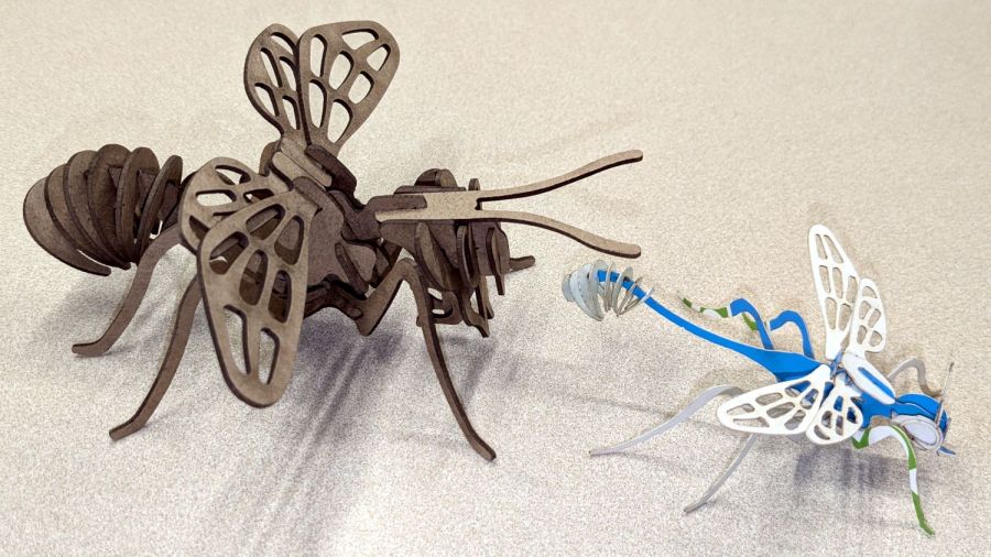
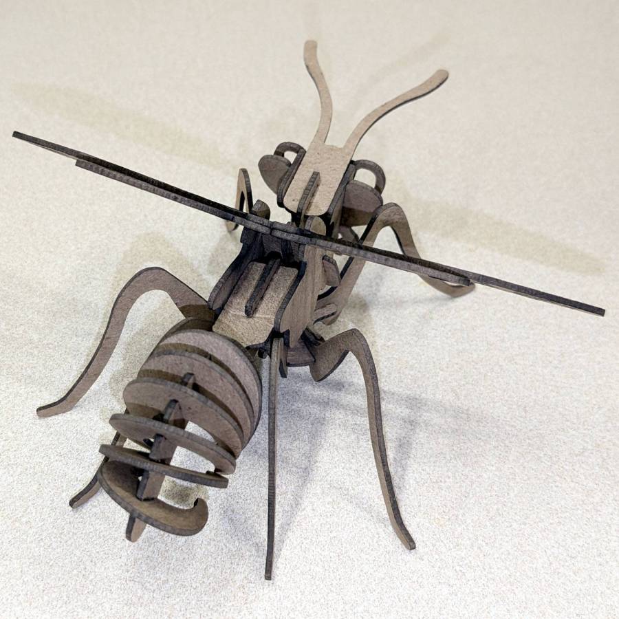
    The little wasp has 0.5 mm slots perfectly suited for very light cardboard. It’s missing a few small pieces because at that scale they just don’t matter.

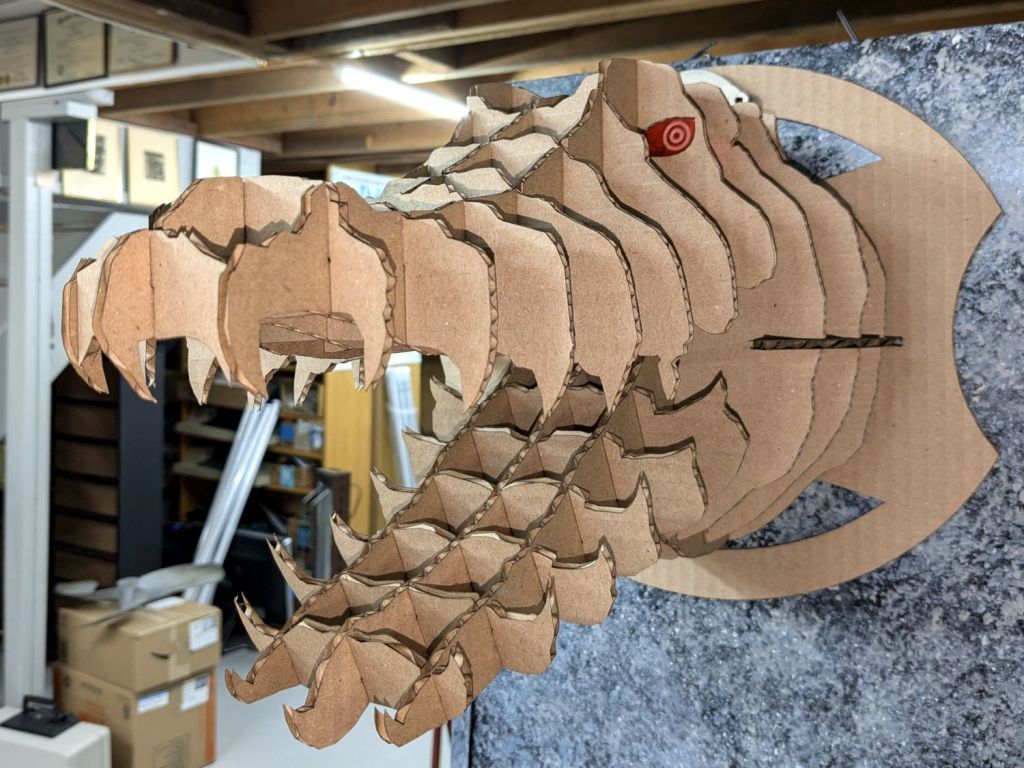
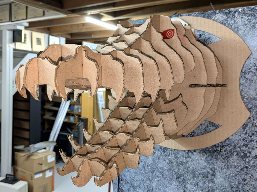
    The chunky bee uses the familiar 1.4 mm chipboard:

    Bee - right front
    Bee – right front

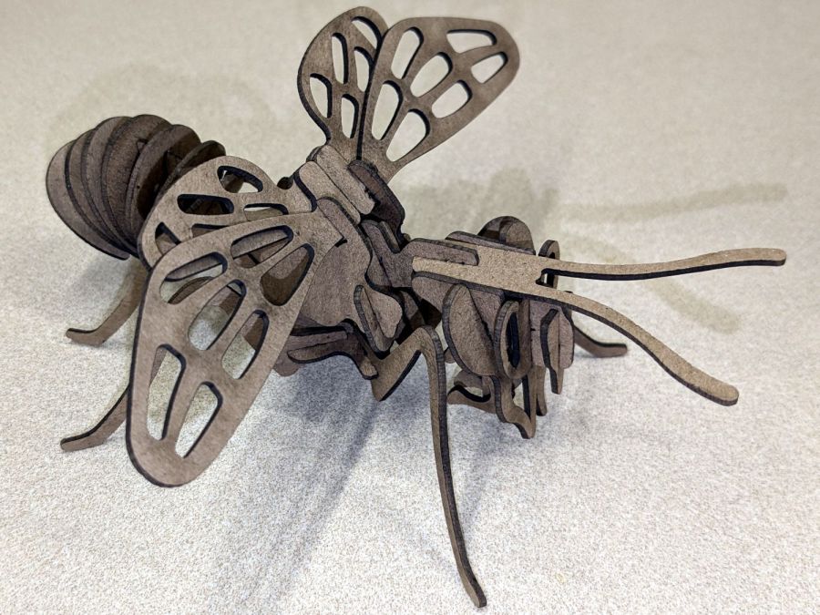
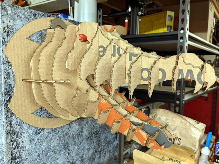
    A rear view to remind me where that long flat slab fits:

    Bee - right rear
    Bee – right rear

    They have far too many pieces for mass production!

  • Slotted Alligator

    Slotted Alligator

    An alligator head should look good at the front door in late October:

    Alligator - left side
    Alligator – left side

    The printing on the moving boxes makes it a bit less scary on the other side:

    Alligator - right side
    Alligator – right side

    Perhaps those are gang tats!

    The eyes are fluorescent acrylic and definitely improve the thing.