The Smell of Molten Projects in the Morning

Ed Nisley's Blog: Shop notes, electronics, firmware, machinery, 3D printing, laser cuttery, and curiosities. Contents: 100% human thinking, 0% AI slop.

Tag: Laser Cutter

  • Layered Paper: LightBurn Random Block Layout

    Layered Paper: LightBurn Random Block Layout

    The Inkscape file contains the overall 16×16 layout of random squares, with the color of each square indicating which of 16 (Inkscape) layers it belongs to:

    Random Blocks - 16x16 159mm - Inkscape layout
    Random Blocks – 16×16 159mm – Inkscape layout

    The next step involves creating a corresponding set of LightBurn layouts to burn those holes out of colored paper sheets to produce layered paper art:

    Random Blocks - framed
    Random Blocks – framed

    I know it’s art, because that’s what I was thinking when I made it.

    Setting up the LightBurn layouts requires enough manual effort to make the whole thing impractical except as a testcase to see how it all worked out. An overview of the LightBurn workspace:

    Random Blocks - 16x16 - LightBurn layout overview
    Random Blocks – 16×16 – LightBurn layout overview

    The little bitty grid in the upper left quadrant represents the 700×500 platform of my laser and each of the blue squares is 159 mm on a side. I tend to not delete the intermediate steps, because they serve as some sort of documentation the next time I wonder how I did that thing.

    So, we begin.

    Import the Inkscape SVG file:

    Random Blocks - 16x16 - LightBurn SVG import
    Random Blocks – 16×16 – LightBurn SVG import

    The blue outer square and the blue text identifying it are on LightBurn’s T2 tool layer, with the black squares on the C00 layer. All of that happens automagically, because I used colors from the LightBurn palette in Inkscape.

    The lonely square in the upper right is the template from which the other 256 squares were cloned, but it has no further purpose in life.

    The 16×16 grid consists of sixteen overlaid groups, which need sorting out for ease of access, so drag each one off into a more useful arrangement:

    Random Blocks - 16x16 - LightBurn sheet separation
    Random Blocks – 16×16 – LightBurn sheet separation

    Note that each of the 256 possible positions has a square in only one of those groups.

    Each of the 16 groups corresponds to a sheet of paper, with the squares indicating holes exposing the sheet below it. The color of each square, as seen from the top of the stack, comes from the first sheet in the stack without a hole. Perforce, every sheet above the one without a hole must have a hole, which means you must merge all those sheets.

    Line up (duplicates of) those 16 groups in the vertical line forming the left column in this arrangement:

    Random Blocks - 16x16 - LightBurn array duplication
    Random Blocks – 16×16 – LightBurn array duplication

    The top group is the layer I named H000 in Inkscape, with the others in order down to H337 on the bottom. You can see why labeling them is pretty much required.

    I should have equalized the vertical spaces between the groups in the left column, but it doesn’t really matter.

    The rest of the triangle comes from duplicating each group using LightBurn’s Grid Array tool with a convenient space between each copy. Make 15 copies of the top group for a total of 16 H000 and no copies of the bottom H337.

    Now the magic happens:

    • Select and duplicate the entire triangle
    • Drag the duplicate off to the side
    • Hit the LightBurn Align Horizontal Centers tool to stack each column into one tidy layout
    • Hit Delete Duplicates to get rid of all the overlaid outer squares
    • If you’re fussy, Duplicate the line of blocks and move it up
    • Group each block individually to keep all the little squares together with the outline

    Thusly:

    Random Blocks - 16x16 - LightBurn combined layers
    Random Blocks – 16×16 – LightBurn combined layers

    Combine each of those blocks with the sheet cutting template, tweak the binary sheet identification holes, and group the result:

    Random Blocks - 16x16 - LightBurn cutting layouts
    Random Blocks – 16×16 – LightBurn cutting layouts

    The leftmost block has All The Holes, the next one is missing a few, and so on across the line:

    Random Blocks - 16x16 - LightBurn cutting layouts - detail
    Random Blocks – 16×16 – LightBurn cutting layouts – detail

    So the leftmost block corresponds to the black mask atop all the layers. Because it doesn’t have alignment holes in the corners or a binary sheet number, you get to align it by eyeball after gluing up the rest of the stack.

    The rightmost block has no cutout squares at all and goes on the bottom of the stack. It also lacks a sheet number, but it’s easy to identify.

    Set the LightBurn speed / power values for the layers to cut your stock of colored art paper.

    Position the Letter Page Holder template to put the center of the sheet cutout at the center of the platform:

    Random Blocks - 16x16 - LightBurn fixture template
    Random Blocks – 16×16 – LightBurn fixture template

    Drop the fixture on the platform, use magnets to hold it down, then do a Print and Cut alignment on the corner targets so the template matches the fixture.

    Then:

    • Click to select one of the blocks
    • Hit Ctrl-D to duplicate it
    • Hit P to slam it to the middle of the template
    • Hit Alt-S to Fire The Laser
    • Hit Del to delete the block
    • Iterate until done

    I used a stack of paper in rainbow order roughly corresponding to the Inkscape layer colors, but you could stack them backwards or even use random colors and nobody would ever know:

    Random Blocks - framed detail
    Random Blocks – framed detail

    I kinda like it, but wow that took a lot of prep work …

  • Layered Paper: Inkscape Random Block Setup

    Layered Paper: Inkscape Random Block Setup

    The random block layered paper design starts as an Inkscape layout, although the amount of manual intervention required to make it happen suggests it’s not really worthwhile. With that in mind, this is how to make it happen …

    Draw a 9×9 mm square with these properties:

    • Undefined fill: each block will become different
    • Flat color stroke set to black with 100% alpha
    • 0.2 mm stroke width: so LightBurn will see it

    Because the squares will be on 10 mm centers, draw a 159 mm square:

    • No fill (this is different from Undefined fill)
    • Flat color stroke set to LightBurn T2 color
    • 0.2 mm stroke width

    Align the big square on the grid, which should have 10 mm spacing because that’s convenient. This will become the way you align the array of squares in the LightBurn layout, so you really want the array to fit neatly and symmetrically inside the 159 mm square.

    Iterate 16 times, all in T2 layer color:

    • Create a layer with a name like H000 through H337
    • Create a corresponding text string
    • Align fussily
    • Duplicate the 159 mm square
    • Put the block and the text string on the new layer
    • Lock the square and text so they can’t move

    Which will look like this:

    Random Blocks - 16x16 159mm - Inkscape layer labels
    Random Blocks – 16×16 159mm – Inkscape layer labels

    Unlike LightBurn, the color is not linked directly to the layer, so each of those text strings is on the corresponding named layer and there are 16 duplicates of the large box at exactly the same coordinates. Plus the original 159 mm square, which remains unlabeled and unlocked.

    Select the black 9 mm block and create a 16×16 clone army array:

    Random Blocks - 16x16 159mm - Inkscape clone setup
    Random Blocks – 16×16 159mm – Inkscape clone setup

    The Initial Color is critical:

    Random Blocks - 16x16 159mm - Inkscape clone color
    Random Blocks – 16×16 159mm – Inkscape clone color

    The layer names come from the 6.25% hue steps, starting with H=0, which will look like this:

    Random Blocks - 16x16 159mm - Inkscape hue steps
    Random Blocks – 16×16 159mm – Inkscape hue steps

    Note that LightBurn absolutely does not care about the colors. All it will get is the outlines corresponding to the strokes, with the colors collecting them into separate groups for the paper layers.

    Go to the Layers window, select the original block (which is likely on Layer 1 or some such), cut it, and paste it somewhere outside the 159 mm square where it won’t cause any trouble.

    Iterate 16 times in the Layers window:

    • Select one of the 256 clone squares, which will have an automagic name like use1272
    • Right-click, hit Select Same → Fill Color
    • Right-click, hit Move to Layer …
    • Pick the layer name matching the hue

    Select all the squares and Distribute randomly:

    Random Blocks - 16x16 159mm - Inkscape rearrange
    Random Blocks – 16×16 159mm – Inkscape rearrange

    Then Align them in a grid:

    Random Blocks - 16x16 159mm - Inkscape grid distribute
    Random Blocks – 16×16 159mm – Inkscape grid distribute

    The 0.8 mm Spacing is the distance between 9 mm blocks with 0.2 mm strokes.

    Shift-click on the 159 mm square to add it to the selection, then hit the two center-align buttons to center the 16×16 array in the square:

    Random Blocks - 16x16 159mm - Inkscape center align
    Random Blocks – 16×16 159mm – Inkscape center align

    Save that sucker as an Inkscape SVG and it’s ready to import into lightBurn.

    With all that done, you can generate different random layouts by:

    • Select the existing 16×16 array (but not the outer 159 mm square; Undo is your friend)
    • Randomize the array
    • Align it
    • Center it

    The colored blocks remain in their corresponding layers, so you need not go through all that overhead ever again.

    Whether that’s worthwhile is up for grabs, but now I have a faint chance of getting it right the next time.

  • Layered Paper: Random Blocks

    Layered Paper: Random Blocks

    I wanted to see / feel what 18 paper layers would look & feel like:

    Random Blocks - framed
    Random Blocks – framed

    That’s a black mask layer atop 16 cut layers of cheerful colored paper in rainbow order and a solid purple sheet at the bottom:

    Random Blocks - framed detail
    Random Blocks – framed detail

    The layer runs at 100 mm/s with 20% of a 60 W laser. The relatively low speed, combined with right-angle corners, produces very crisp results unlike the rounded-corner Subpixel holes.

    The holes form a 16×16 grid and cutting the first few layers with 250-ish holes takes a bit under three minutes apiece:

    Random Blocks - cutting red layer
    Random Blocks – cutting red layer

    The sheets sit in the Letter sheet fixture and get four round holes in the corners for the assembly fixture, plus a binary sheet ID helping me with the stacking order:

    Random Blocks - assembly process
    Random Blocks – assembly process

    The hole patterns come from Inkscape through LightBurn, in a grindingly intricate manual process crying out for automation. This is a feasibility study to see if the result is worthwhile and, yeah, it looks promising. More about all that later.

    If someone had asked Young Me what I’d be doing in half a century, dabbing colored paper with a glue stick would not have been one of my choices and not just because glue sticks hadn’t been invented back then.

    Another couple of years and I’ll be ready for the Activity Room at the Olde Folkes Home.

  • Snowflake Coaster: One Year Later

    Snowflake Coaster: One Year Later

    After more-or-less constant use under a cup in the bathroom, a Snowflake Coaster has reached the end of its life:

    Snowflake coaster - 1 yr use
    Snowflake coaster – 1 yr use

    The acrylic flake is fine, but the wood has mildewed:

    Snowflake coaster - 1 yr use - detail
    Snowflake coaster – 1 yr use – detail

    It’s second from the left in the bottom row:

    Snowflake Coaster - assortment
    Snowflake Coaster – assortment

    All except the pair in the left column had a coat or two of rattlecan clear, which suggests wood-ish coasters need something much more durable, along the lines of clearcoat epoxy. No surprise there!

  • Plastic Spring Clamp Jaw Rod Replacement

    Plastic Spring Clamp Jaw Rod Replacement

    A recent quilt photo shoot degenerated into me chasing several bright orange clamp jaws across the deck as they popped off their clamps hanging from the photo backdrop scaffold. Most clamps have jaws snapping onto actual rods, but these clamps have molded-in-place “rods” much smaller than the 2 mm expected by the jaws and much more irregular than seems reasonable.

    Trace and scan the nose of a clamp:

    Large spring clamp nose outline
    Large spring clamp nose outline

    Curiously, the molded rod is not centered in the nose:

    Large spring clamp nose - pin locatIon
    Large spring clamp nose – pin locatIon

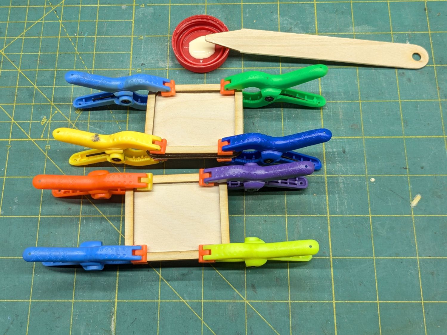
    Use LightBurn to coerce a scan of the first sketch into a suitable path, laser-cut some MDF, and glue up a drill fixture:

    Spring clamp jaw pins - fixture gluing
    Spring clamp jaw pins – fixture gluing

    Align the drill to the center of the off-center hole marked on the bottom layer:

    Spring clamp jaw pins - drill alignment
    Spring clamp jaw pins – drill alignment

    The drilling setup looks casual, but hand-holding the clamps against the rear wall and into the form-fitting nose recess sufficed:

    Spring clamp jaw pins - fixture overview
    Spring clamp jaw pins – fixture overview

    I snipped the plastic “rods” out before drilling the holes, then rammed 2 mm steel rods in place:

    Spring clamp jaw pins - steel
    Spring clamp jaw pins – steel

    They’re really 5/64 inch = 1.98 mm rods from the oil-hardening drill rod stash, but entirely sufficient for the purpose.

    With one clamp in hand, though, there was obviously no reason for the rods to be off-center. So I centered the drill in the nose, punctured the rest of the clamps, and pressed 2 mm carbon fiber rods in place:

    Spring clamp jaw pins - steel vs carbon fiber
    Spring clamp jaw pins – steel vs carbon fiber

    The rods were cut to 20 mm by rolling them across a pad with firm pressure from a utility knife. That was mostly to get some experience cutting carbon fiber, which is obviously overqualified for the job.

    Snap the orange jaws in place and I shall never suffer the embarrassment of chasing them again …

  • Rolling Bed Stop

    Rolling Bed Stop

    The upstairs Sewing Room came with a couch-like bed incorporating a roll-out trundle bed. It doesn’t get a lot of use, but it lacks wheel locks and tends to scoot away unless you get into it rather more carefully than seems reasonable.

    So I made a pair of stops to capture the wheels:

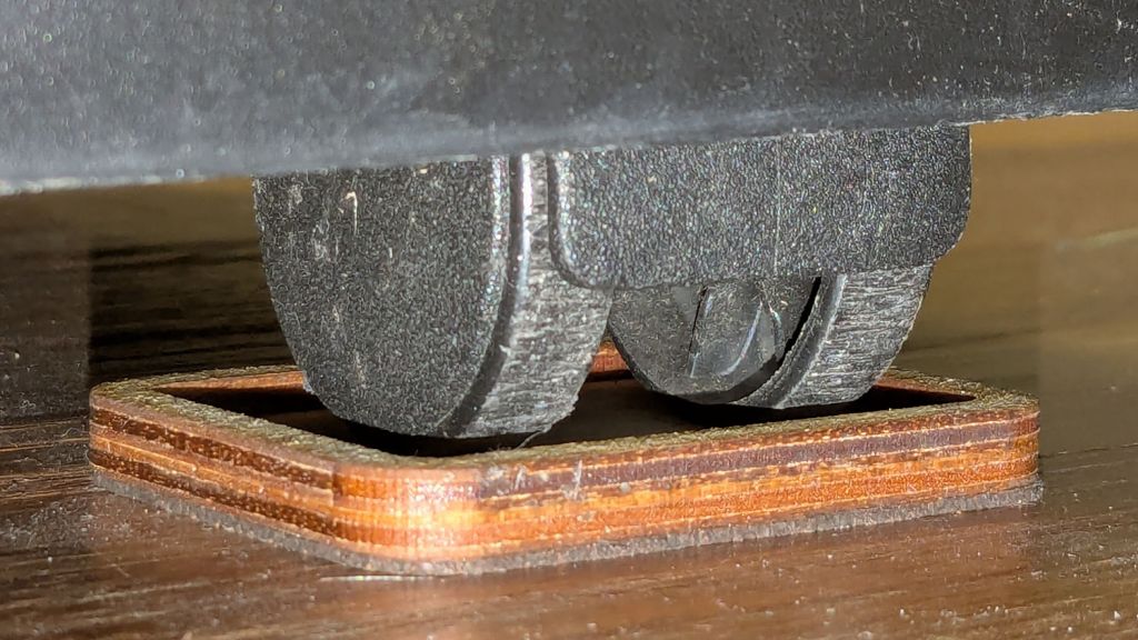
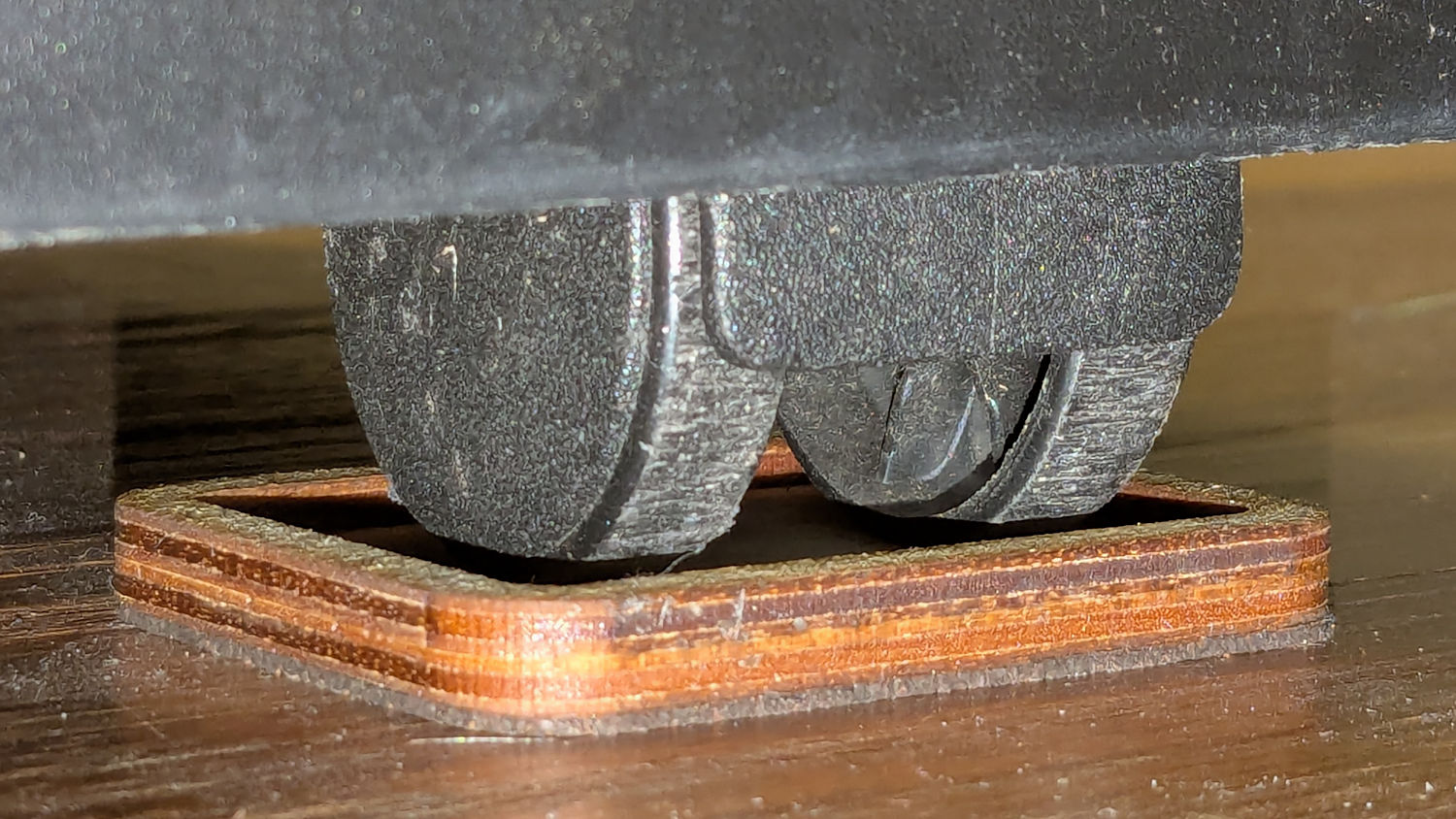
    Rolling Bed Stops - installed
    Rolling Bed Stops – installed

    The solid model shows they’re just plastic blocks minus a model of the roller wheel:

    Rolling Bed Stops - solid model - show view
    Rolling Bed Stops – solid model – show view

    I like the wood-grain effect of the doubly curved recess on printed plastic layers, even if nobody will ever see it:

    Rolling Bed Stops - PrusaSlicer
    Rolling Bed Stops – PrusaSlicer

    The OpenSCAD code also exports a projection of the block as an SVG file to laser-cut the cork pad.

    Roll the trundle bed into position, push the stops against the wheels, lift and pull forward an inch, let it down, and the wheels snap into those recesses.

    These are considerably fancier than some of the other wheel stops / feet around the house, if only because I got to use the Chord Equation to solve for the radius of the circle parallel to the axle for a snug socket.

    The OpenSCAD source code as a GitHub Gist:

    // Rolling Bed roller stops
    // Ed Nisley – KE4ZNU
    // 2025-06-16
    include <BOSL2/std.scad>
    Layout = "Show"; // [Show,Build,Roller,Plan]
    /* [Hidden] */
    HoleWindage = 0.2;
    Protrusion = 0.1;
    ID = 0;
    OD = 1;
    LENGTH = 2;
    WallThick = 10.0; // default width for things
    BaseThick = 3.0; // bottom thickness
    RollerOA = [47.2,49.8,40.0]; // min & max dia, length
    FrameClearance = 11.0; // max height under bed frame at roller
    PadOA = [RollerOA[LENGTH] + 2*WallThick,RollerOA[OD],FrameClearance – 1.0];
    //———-
    // Define Shapes
    module Roller() {
    m = (RollerOA[OD] – RollerOA[ID])/2;
    RollerR = (m^2 + (RollerOA[LENGTH]^2)/4) / (2*m);
    up(RollerOA[OD]/2)
    yrot(90)
    rotate_extrude($fa=1)
    intersection() {
    left(RollerR – RollerOA[OD]/2)
    circle(r=RollerR,$fa=1);
    rect([RollerOA[OD]/2,RollerOA[LENGTH] + 2.0],anchor=LEFT);
    }
    }
    module RollerStop() {
    difference() {
    cuboid(PadOA,anchor=BOTTOM,rounding=WallThick/2,except=BOTTOM);
    up(BaseThick)
    Roller();
    }
    }
    //———-
    // Build things
    if (Layout == "Plan") {
    projection(cut=true)
    RollerStop();
    }
    if (Layout == "Roller") {
    Roller();
    }
    if (Layout == "Show") {
    RollerStop();
    color("Green",0.5)
    up(BaseThick)
    Roller();
    }
    if (Layout == "Build") {
    RollerStop();
    }
  • Screen Door Handle Repositioning

    Screen Door Handle Repositioning

    For unknown reasons, the handle on the porch screen door was installed less than one finger width from the frame, so I conjured a pair of plastic plates shifting it far enough to prevent finger pinches and avoid the screws for the outside handle:

    Porch door handle repositioning
    Porch door handle repositioning

    The original holes now have M4 threaded wood inserts and the holes in the ¼ inch acrylic have M4 heat-staked brass inserts, mostly because I had everything on hand.

    This was part of a project to trim the bottom of the door to clear the porch floor boards, which evidently continued warping after they trimmed the door to fit:

    Porch door trimming
    Porch door trimming

    That thin blue line suggests the highest part of the floor was once near the bottom of the picture, but it’s now the lowest part. The highest part is now near the hinge side near the top of the picture, firmly jamming the door in place.

    Works great now!