Ed Nisley's Blog: Shop notes, electronics, firmware, machinery, 3D printing, laser cuttery, and curiosities. Contents: 100% human thinking, 0% AI slop.
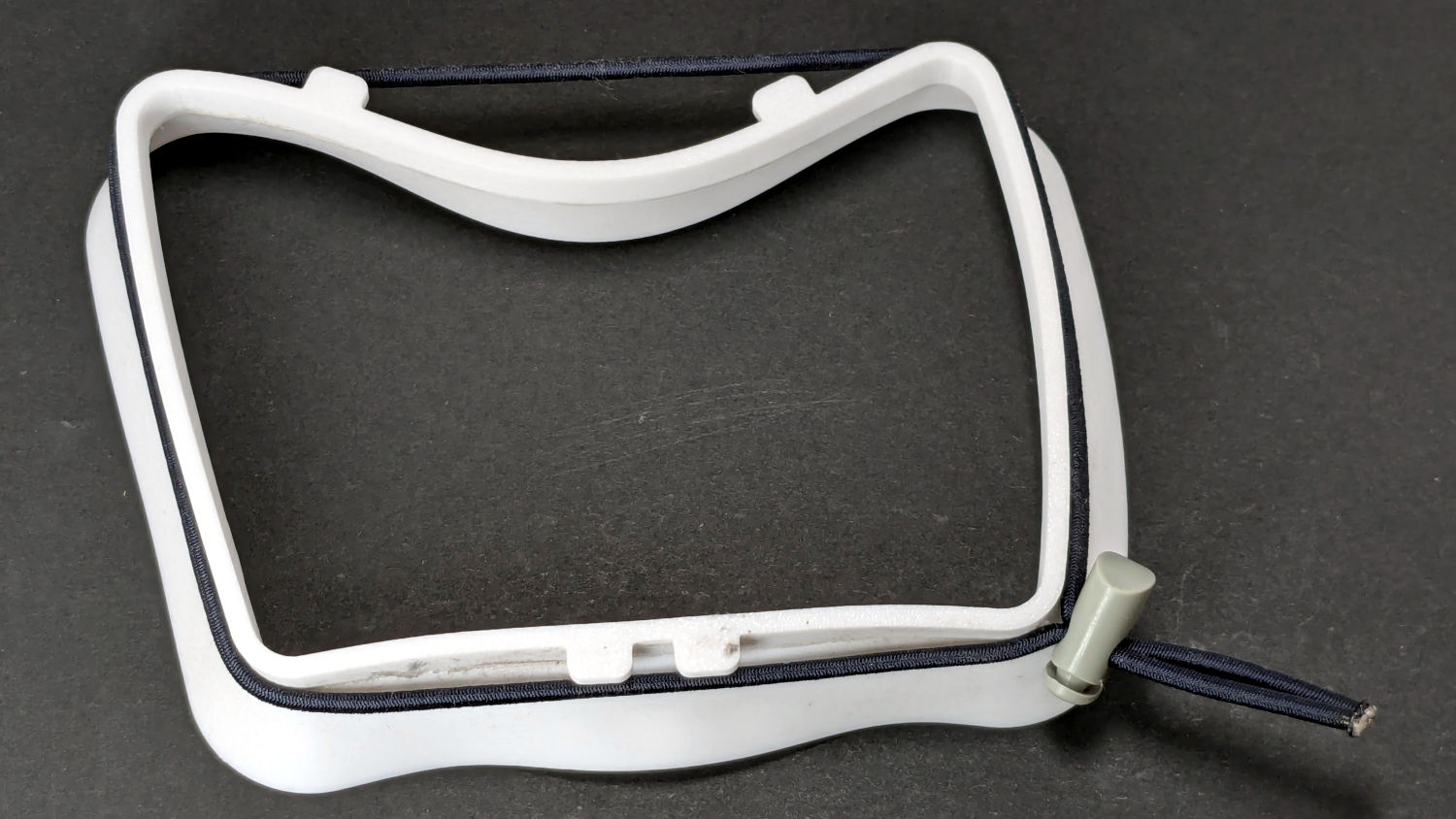
Seen with the shock cord in place, it’s obvious that combining moderately high temperature with steady compression sufficed to bend the PETG enough to pop those tabs loose from the vent.
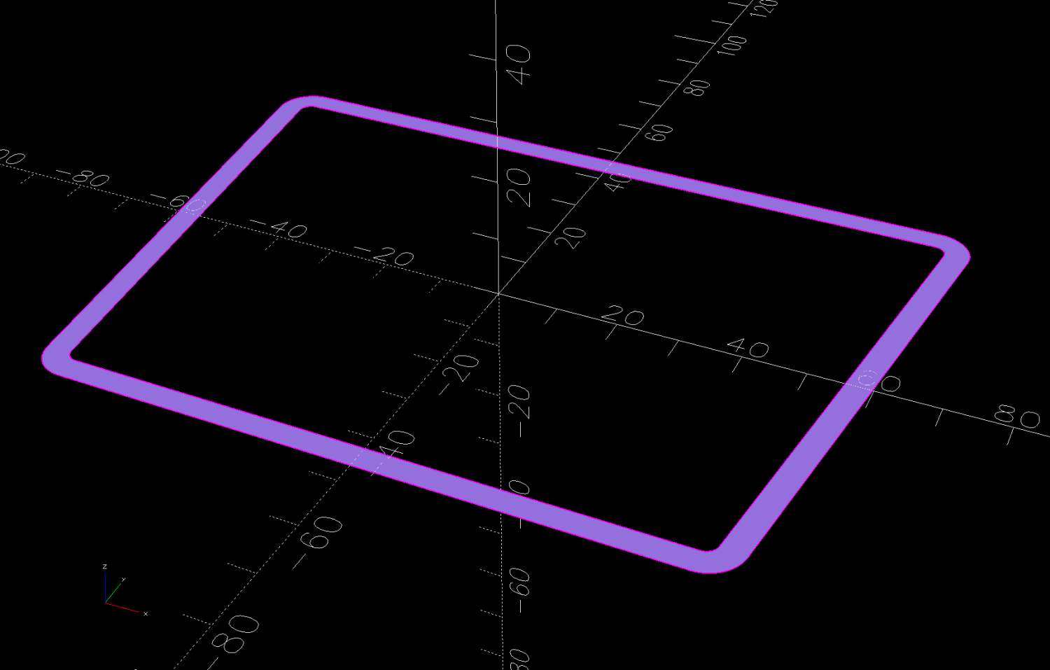
So the OpenSCAD model now produces a stiffening ring to be laser-cut from acrylic:
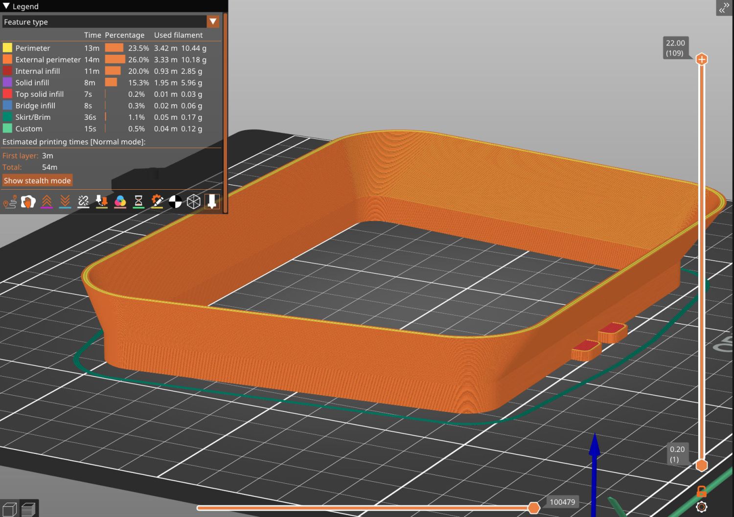
The whole snout builds as a single unit in the obvious orientation:
Clothes Dryer Vent Filter Snout – V2 – slicer
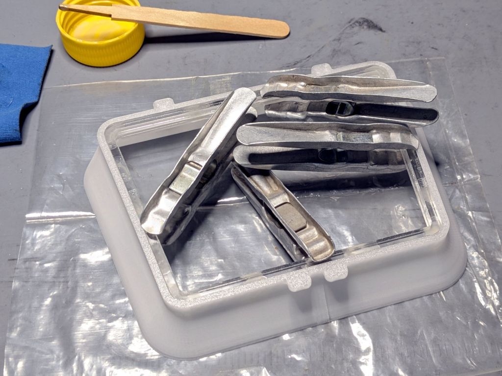
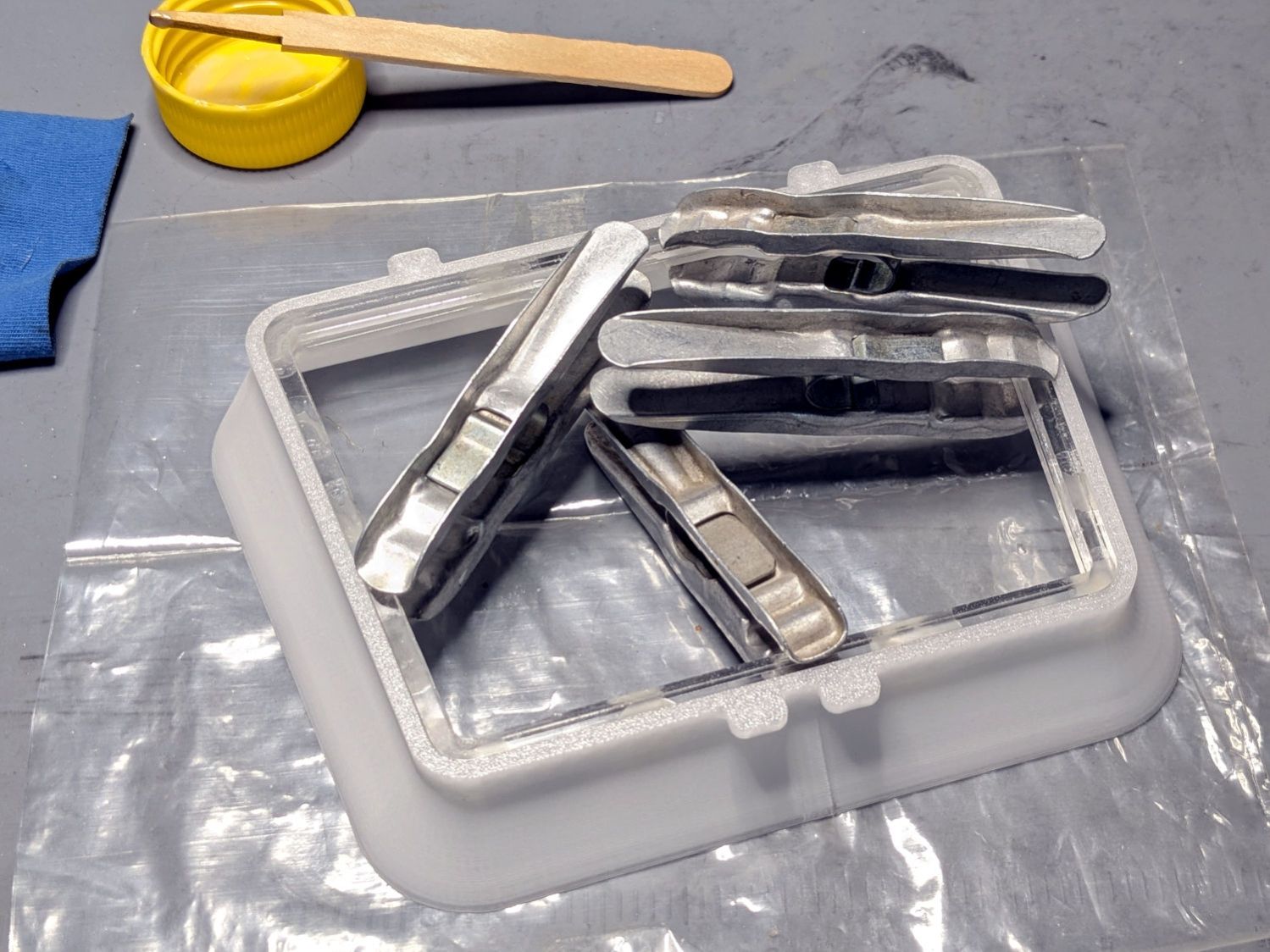
Because the part of the snout with the tabs is 7 mm tall, I glued a 4 mm acrylic ring to a 3 mm ring, with both of them glued to the snout:
Clothes Dryer Vent Filter Snout – acrylic gluing
That’s “natural” PETG, which I expected to be somewhat more transparent, but it’s definitely not a dealbreaker.
Mary will sew up another cheesecloth filter and we’ll see what happens to this setup.
As the saying goes, “Experience is what you get when you don’t get what you want.”
Fortunately, living in the future makes it easy to iterate on the design & implementation until experience produces what should have been obvious at the start.
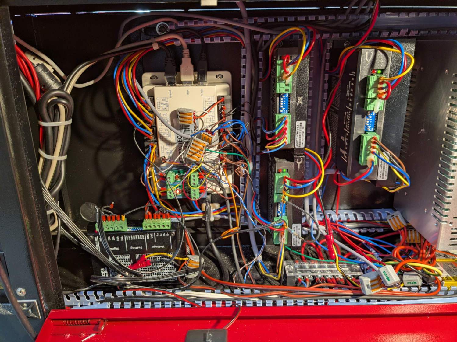
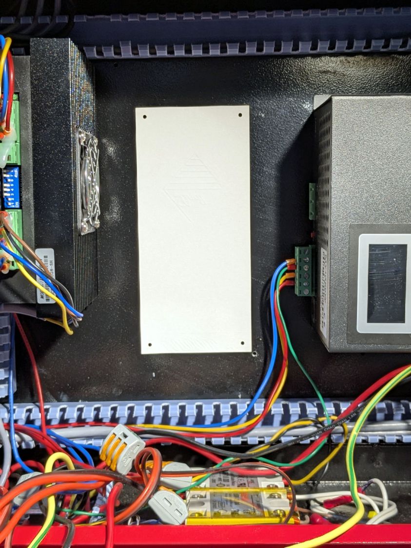
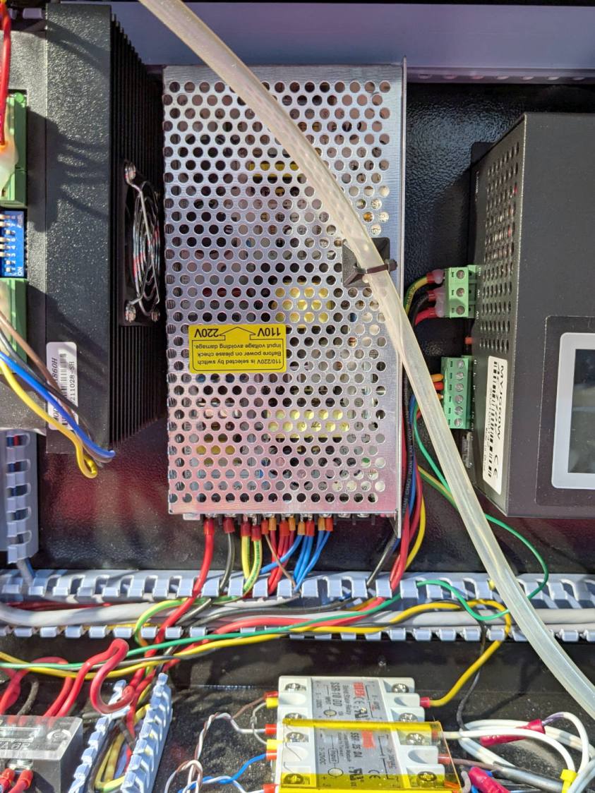
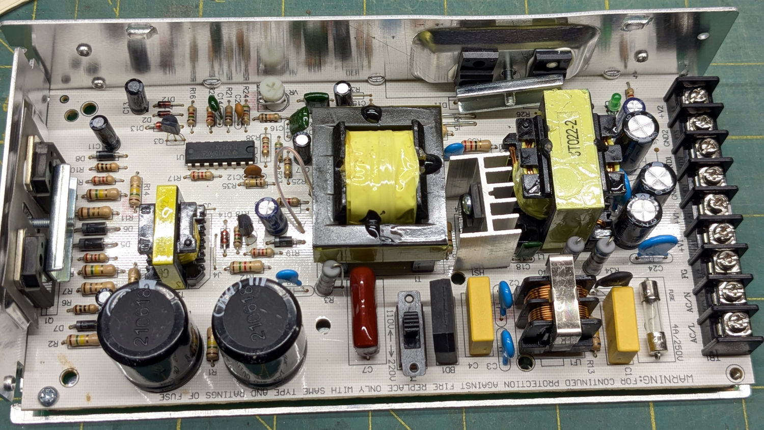
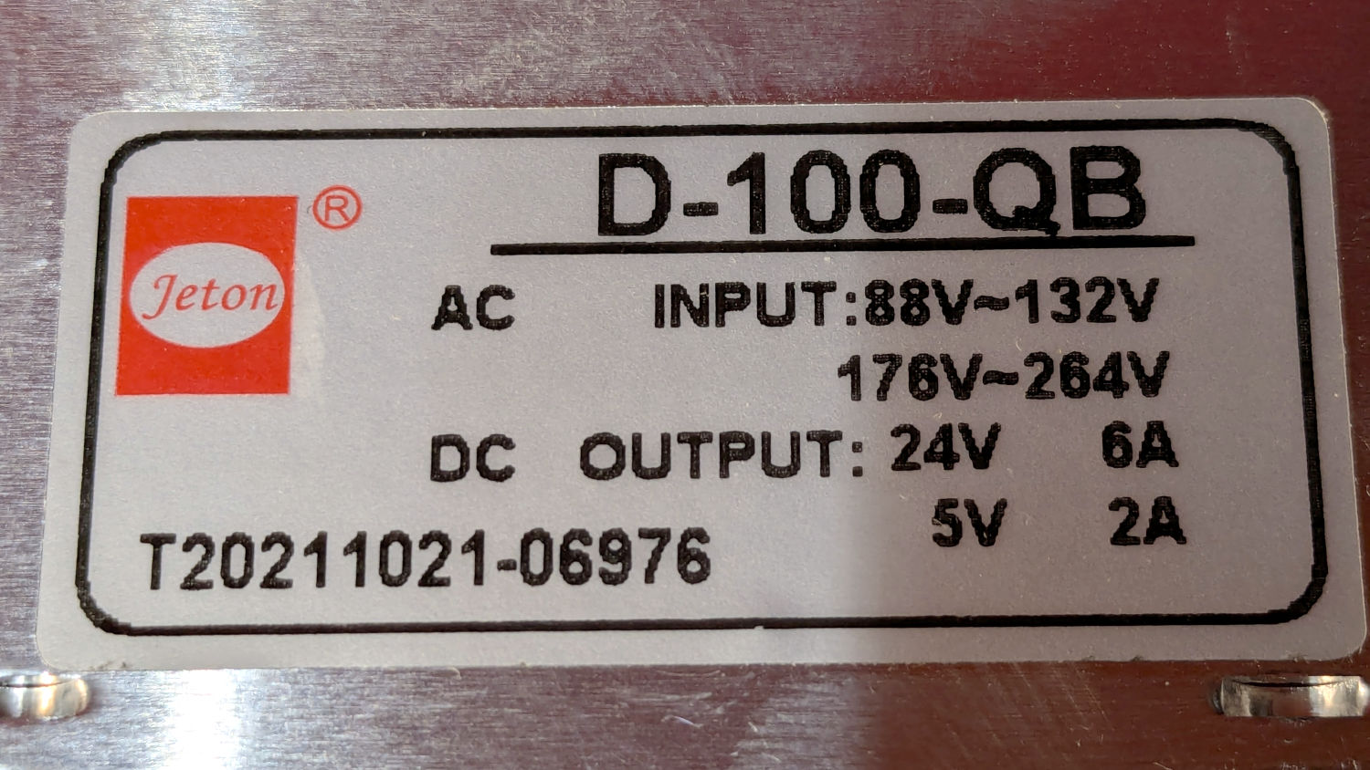
The OMTech 60 W laser has a 24 V + 5 V power supply for the stepper motors and, I had always assumed, the feeble LED strip light on the gantry:
OMTech 60W laser – OEM lighting
The stepper motor driver settings, plus a few amps for the controller and suchlike, added up to something over 12 A, far more than the 24 V supply’s 6 A spec should produce. When I added the COB strip lights around the platform, I dropped a 24 V wall wart into the electronics bay to avoid abusing that poor supply:
OMTech 60W laser – COB LED strips
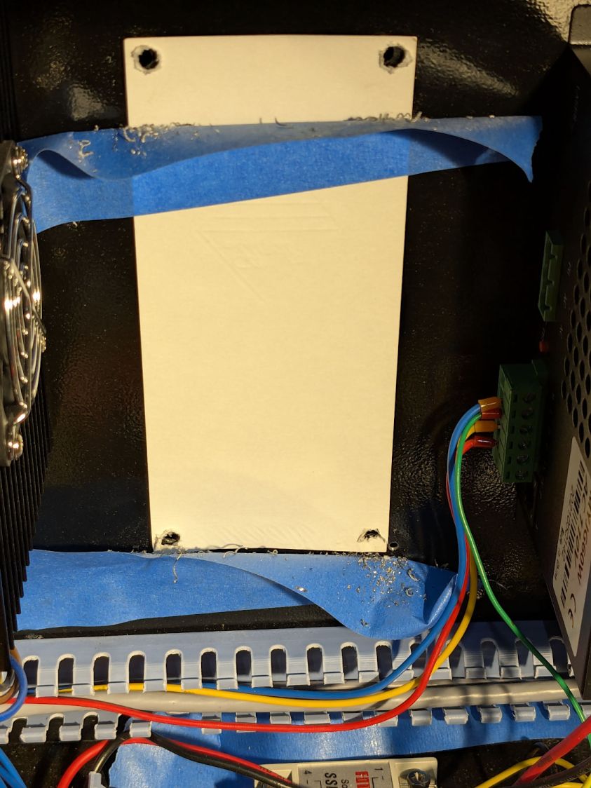
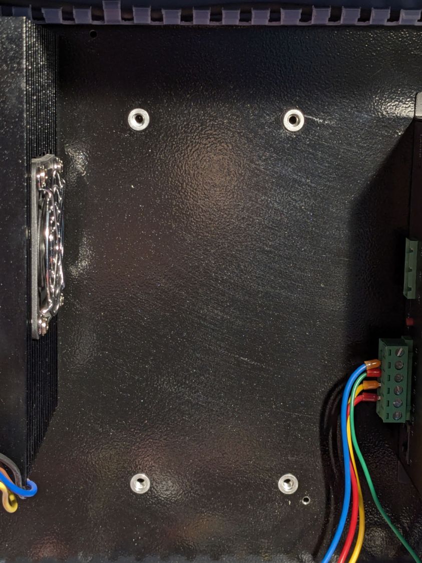
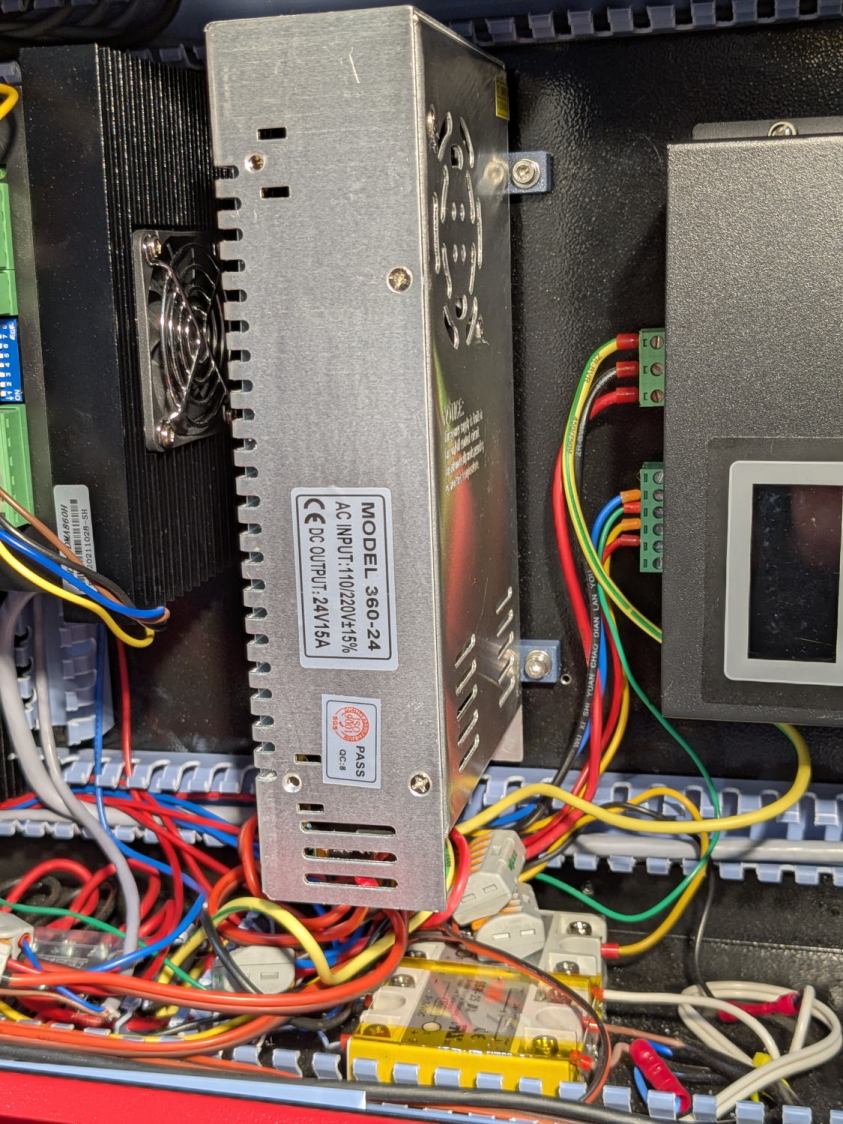
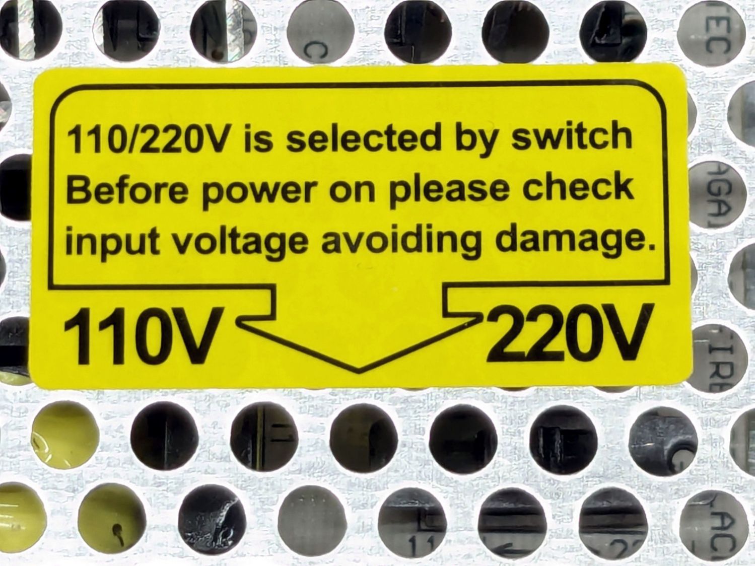
For reasons to be described later, it’s now time to upgrade that 24 V power supply to a 15 A supply that’s been on the shelf for far too long. However, it does not have a 5 V output, so it’s also time to figure out how much 5 V power the laser really needs.
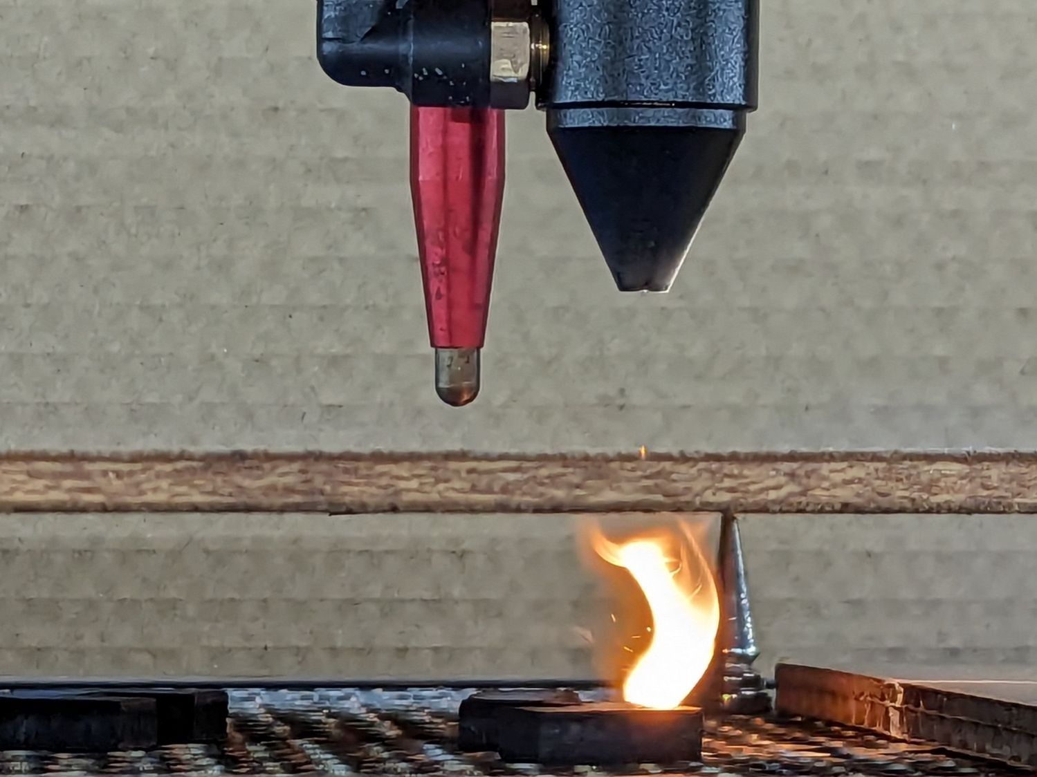
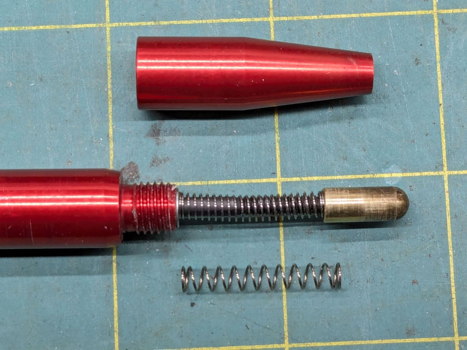
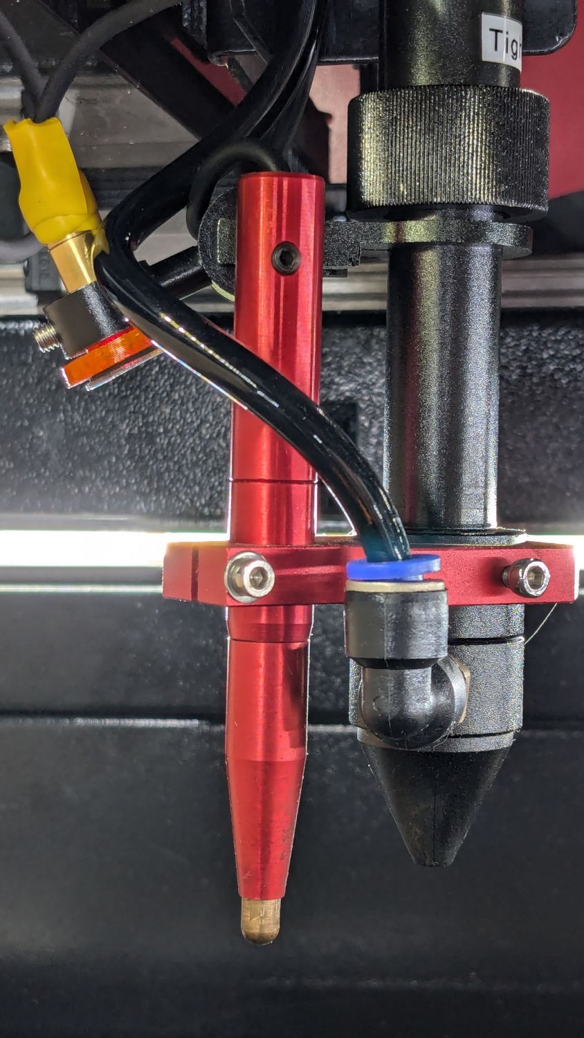
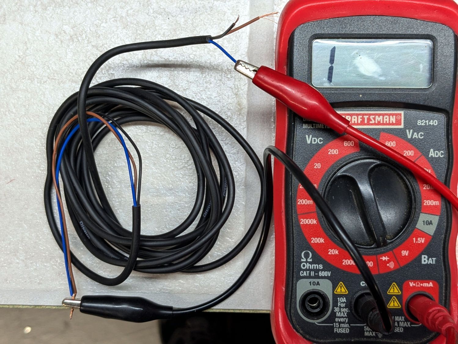
A quick measurement suggested the 5 V output delivered 20 mA to something. After convincing myself the multimeter was working and that the gantry LED strip was still lit, I finally tracked the wire pair to the red-dot pointer:
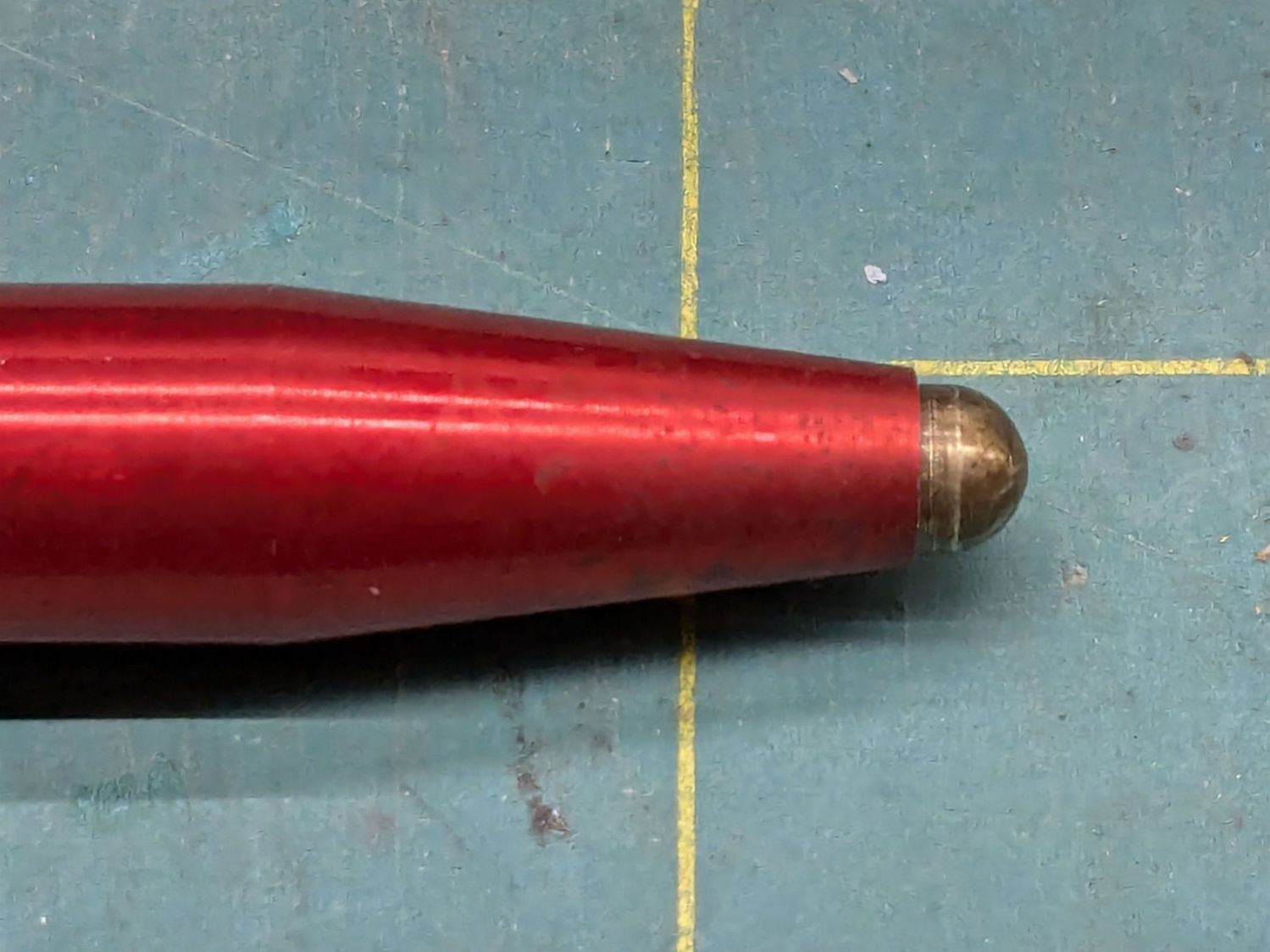
OMTech red dot pointer – polarizing filter installed
Yeah, a whole dual-output power supply for one red-dot laser module.
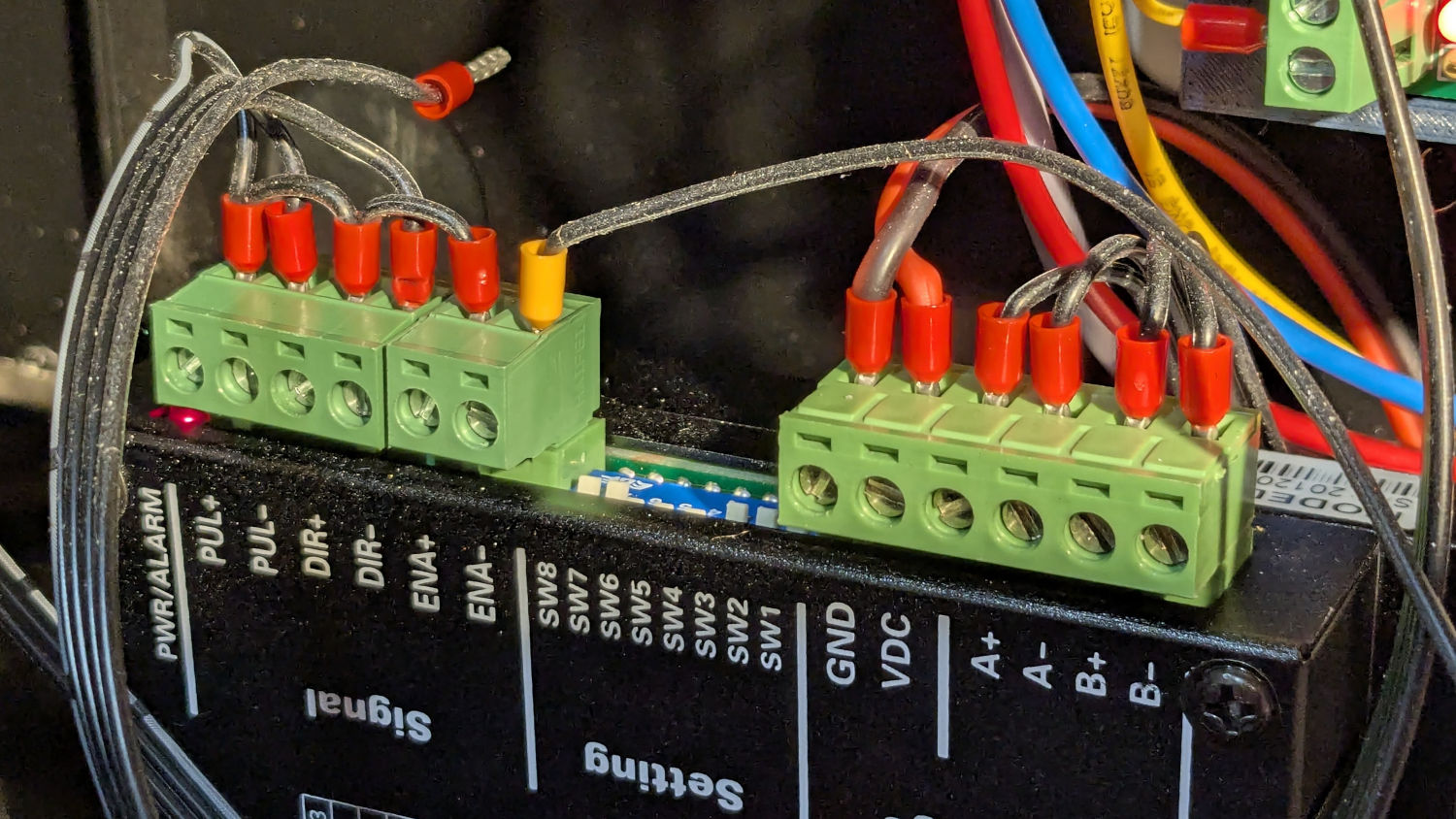
Conveniently, the KT332N controller has several 5 V outputs and the LIMIT terminal block even has a GND terminal on the other end:
KT332N Limit Terminals – OEM
Prying off the hot melt glue, extracting the red-dot pointer wiring from the raceway, crimping ferrules on a couple of jumpers, and deploying a pair of Wago connectors:
KT332N Limit Terminals – red dot wiring
I am still not accustomed to the color code:
Black = signal
Brown = power
Blue = GND
But it’s like that and that’s the way it is.
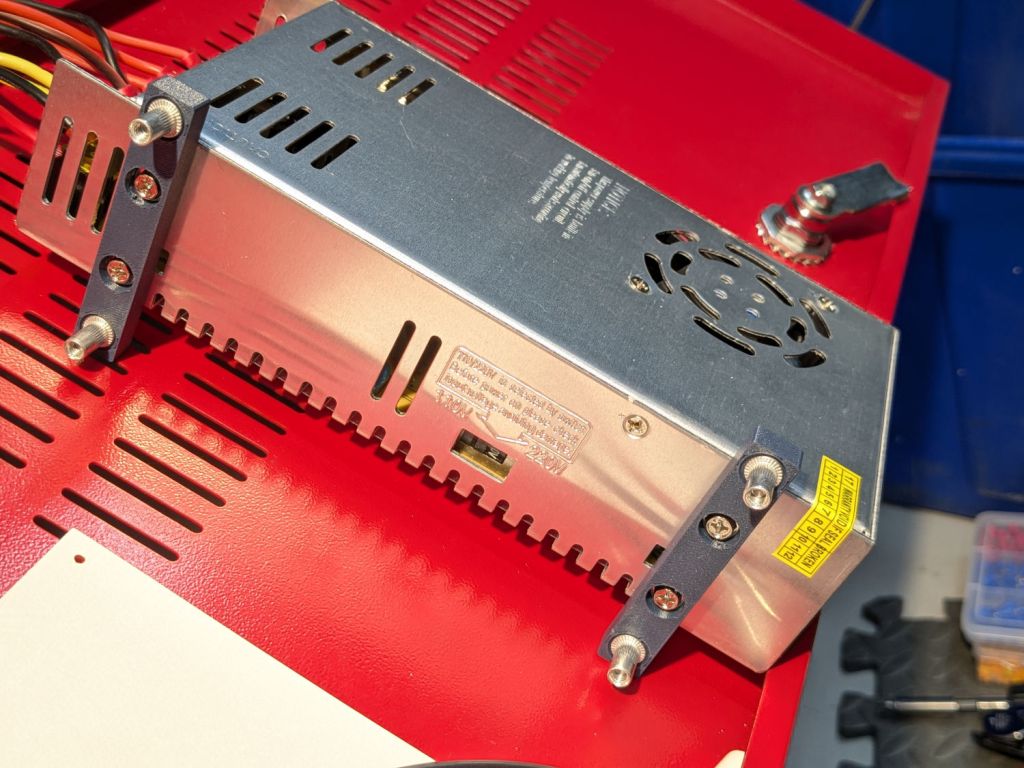
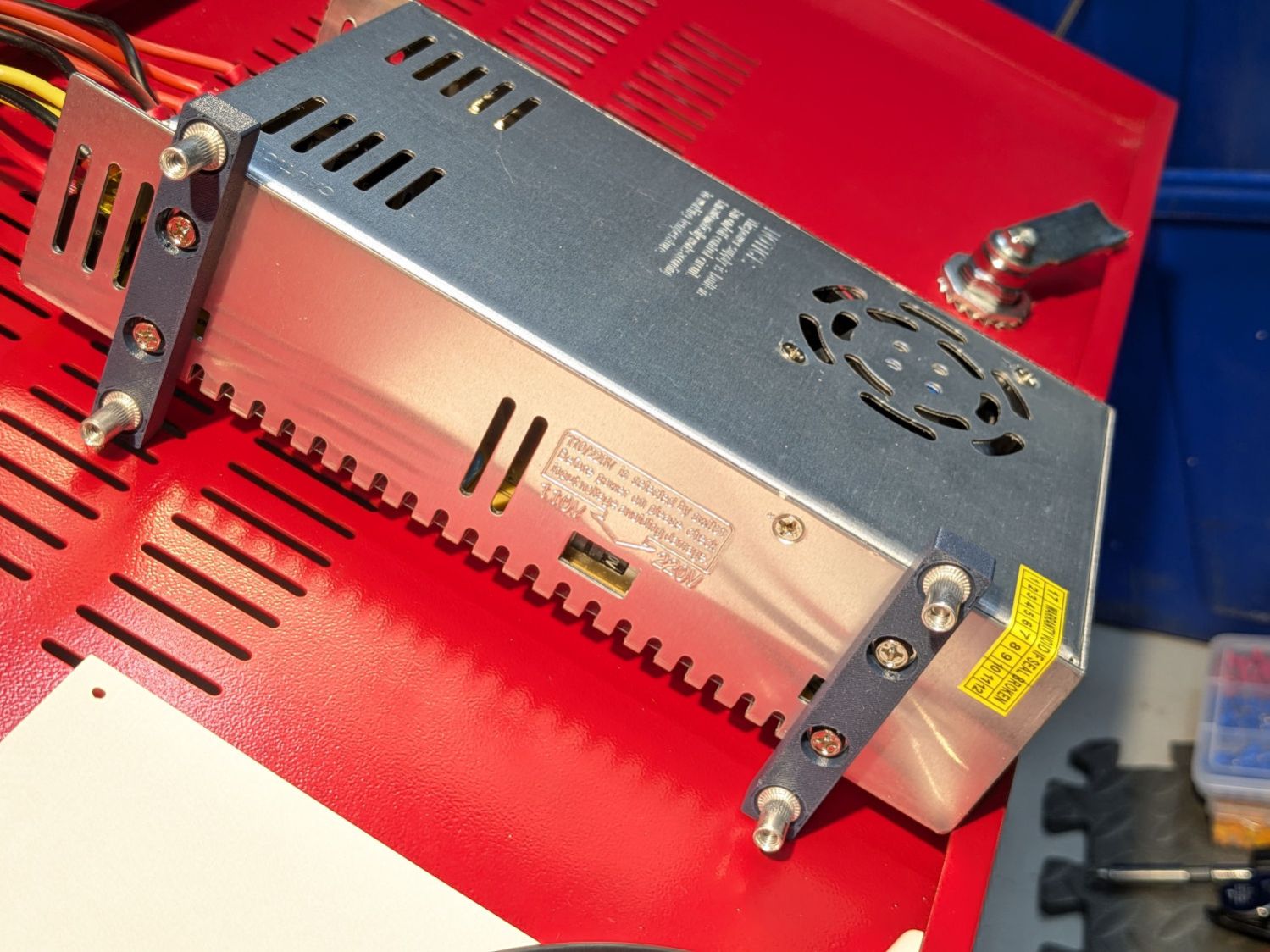
The red dot lit right up, the gantry LED strip obviously uses 24 V power, and I must shoehorn a slightly larger 24 V supply into the space currently occupied by the old supply.
The cart in Mary’s Vassar Farm plot returned in need of repair:
Garden Seat – fractured body
Those fractures near the end of the axle let the axle erode the side wall:
Garden Seat – eroded body
This will obviously require some sort of reinforcement on the body holding the axle, but the first challenge involved getting the wheels off the axle:
Garden Seat – axle cover
Some brute force revealed the hub covers snapped over an install-only locking fastener:
Garden Seat – axle retaining clip
More brute force cut those fasteners (a.k.a. star-lock washers) to get the wheels off the axles.
While contemplating the situation, a box of 606 bearings (as used in the PolyDryer auto-rewind spindles) failed to scamper out of the way and produced a victim fitting perfectly on the 8 mm axle:
Garden Seat – bearing idea
I regard such happenstance as a message from the Universe showing I’m on the right track. The alert reader will note the axle should not rotate, but does sport scars showing it’s done some turning in the recent past, so the bearing may not be a completely Bad Idea™.
Finding a Lexan snippet exactly as thick as the bearing suggested bolting a plate across the side of the body to support the bearing, like this:
Garden Seat – reinforcing plate installed
Some layout work in LightBurn produced a template to mark the body for hand-drilling the holes:
Garden Seat – drill marking template
In retrospect, that was a mistake. I should have:
Laser-cut an MDF sheet to make a drill jig
Drilled one hole and inserted a screw
Drilled the rest of the holes in exactly the right places
Instead, three of the holes in that nice Lexan sheet ended up slightly egg-shaped to adjust for mis-drilled holes in the body.
I squeezed 5 mm rivnuts into whatever fiber-reinforced plastic they used for the body, which worked better than I expected. They’re intended for sheet metal, so I set the tool for 5 mm compression and they seem secure. I hope using plenty of screws across a large plate will diffuse the stress on each screw.
In this situation, I regard JB KwikWeld epoxy as “removable with some effort”, as opposed to the destruction required with those star-lock washers. High-strength Locktite might also be suitable, but I do not anticipate ever having to remove these again for any reason and do not want the nuts to fall off in the garden.
Mary’s Hens and Chicks gardening group is having a White Elephant gift swap, where one can get rid of anything vaguely garden-related without repercussions, so I ran off a set of eponymous coasters for practice:
Hens and Chicks Coasters – overview
They’re 3 mm laser plywood with English Chestnut stain and satin polyurethane sealant, with PSA cork on the underside. Even if (IMO) the stain came out too dark on some of them, they’re perfectly suited for the occasion.
It’s ordinary laser-grade 3 mm plywood with another wood inlay, sanded flat and covered with polyurethane sealer.
The key attraction: not fiddling with tiny veneer bits.
Cut the recesses in one pass with enough energy to make them at least as deep as the veneer thickness:
Marquetry test – plywood cutting
Press the veneer onto aluminum tape, taking care to avoid wrinkles and folds, and cut away everything that doesn’t go into those recesses:
Marquetry test – veneer cutting
Which looks gnarly when you’re done:
Marquetry test – veneer on tape
I cut the aluminum tape to fit within the corner targets around the plywood layout, thus simplifyingmaking possible aligning the positive veneer shapes with the negative plywood shapes while being unable to see either of them.
Slather wood glue over the plywood, make sure even the tiniest recesses are filled, align the aluminum, clamp the two firmly together, wait for a few days while the glue cures in that airless space, then peel off the aluminum:
Marquetry test – peeled
Which looked so awful I thought that was a disaster, not least because the veneer stood proud of the plywood, so it remained on the back of the bench for far too long.
Eventually, having deployed the sander for another project, I sanded the veneer flush with the plywood to reveal the nearly perfect results in the lead picture. There’s a bit of smoke stain left in the grain, but the tiniest recesses have at least some veneer fill and the surface is entirely smooth.
The overlaid circles worked out:
Marquetry test – detail 1
The darkest block and the smaller lines are badly smoke-stained veneer, as they have wood grain visible under magnification. I think those may not have fully entered their recesses and we’re seeing a very thin veneer layer soaked with soot-filled wood glue.
Another view:
Marquetry test – detail 2
The checkerboard squares worked well;
Marquetry test – squares 1
To my astonishment, even the 0.5 mm squares have some veneer inside, as do the 0.5×1.0 mm rectangles on the left:
Marquetry test – squares 2
Not knowing any better, there’s no kerf offset on any of the figures and they’re separated by about the 0.2 mm width of the focused spot.
Aligning the veneer to the recesses was tricky and I was not at all sure it had happened. I think larger shapes would be much easier and might give off a confirming squish as they meet their sockets.
Gotta try that again without the benefit of beginner’s luck.
Having used desiccant in tea bags inside the PolyDryer boxes with some success, I wanted to see what happens with more exposed surface area:
Polydryer Box desiccant tray – installed
The tray (jawbreaker boxes.py URL) is 2 mm chipboard with a quartet of additional notches fitting the protrusions in the bottom of the Polydryer box:
Polydryer Box desiccant tray – assembly
Although you’ll find plenty of printed trays, many with ingenious perforated lids, this was quick & easy:
Polydryer Box desiccant tray – cutting
They’re painfully prone to dumping their contents, despite the dividers which are intended to dissuade the beads from taking collective action and surging over the slightly higher outer walls. Fortunately, the dump occurs inside a sealed box and is entirely survivable.
Distributing 25 g of silica gel neatly fills the sections:
The ancient and much–repaired Sears humidifier works better in its new location across the living room with its front raised a few millimeters, which may have something to do with its plastic housing supporting a pair of heavy water containers for a few decades.
After fiddling around with shims to find the proper height, these feet descended from the Husky workbench feet:
Humidifier Caster Feet – installed
They’re glued up from 3 mm plywood sitting on a 1 mm layer of cork:
Humidifier Caster Feet – clamping
The humidifier seems much happier with its casters 4 mm above the floor. Seems awfully fussy to me, but there’s no arguing with success.