Ed Nisley's Blog: Shop notes, electronics, firmware, machinery, 3D printing, laser cuttery, and curiosities. Contents: 100% human thinking, 0% AI slop.
The laser-engraved guide lines confused GIMP’s edge detection to no end.
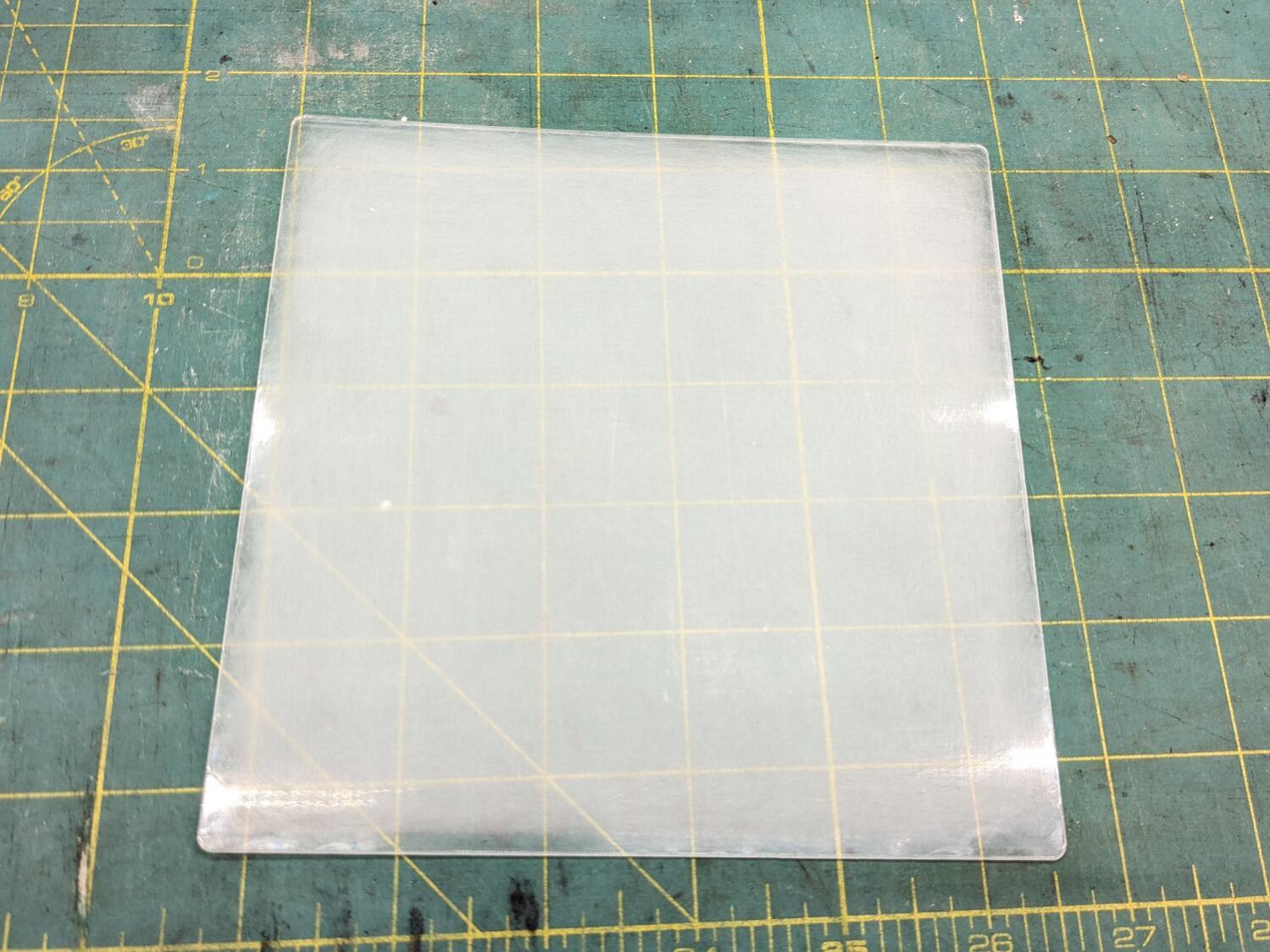
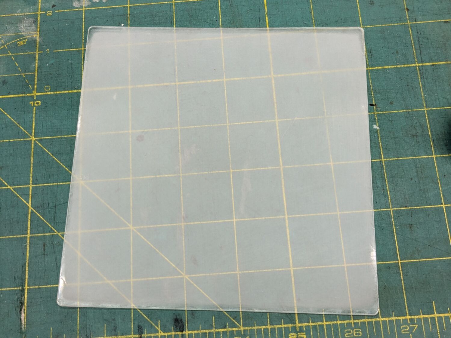
It came from a large sheet of 1 mm acrylic, formerly a poster cover, bearing scars of its long history in the “might be useful someday” stash. I wondered if I could remove enough scratches and scuffs to ease GIMP’s workload.
Stipulated: I am a cheapskate.
Laser-cut a suitable sheet and sand both sides with 220 grit paper to what looked like a uniform surface:
Acrylic polishing – 220
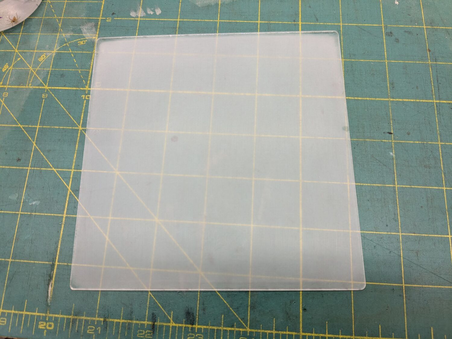
Continue scrubbing with 400, 800, 1000, 1500, and 3000 grit papers:
Acrylic polishing – 3000
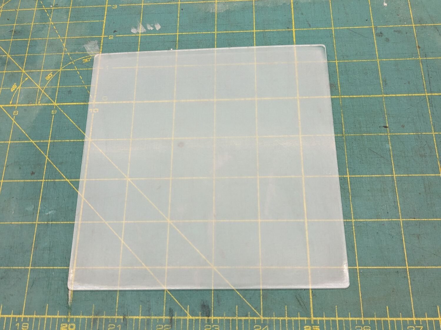
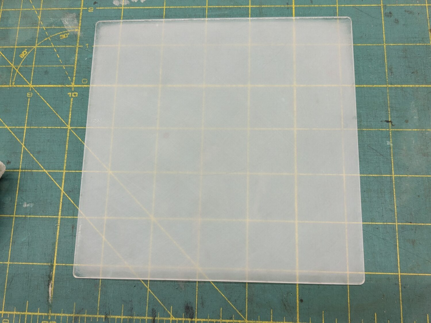
Massage it with Novus Polish 3, 2, and 1:
Acrylic polishing – Novus 1
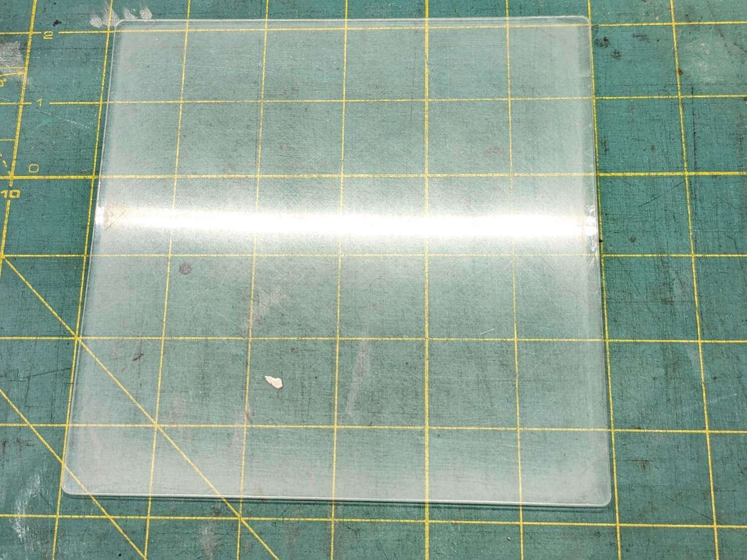
At best, it’s more translucent than transparent and definitely not an optical-quality polishing job:
Acrylic polishing – translucency
Fortunately, I need not care about the edges, because it goes in a square frame with a circular cutout.
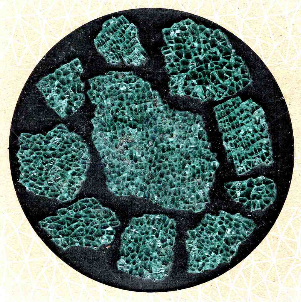
Tape it into that cardboard frame, scan it against a black background, and blow out the contrast to show I should have started with 100 grit paper and paid more attention to that “uniform surface” thing:
Acrylic polishing – scratches
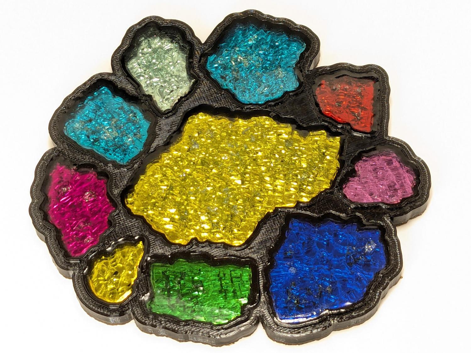
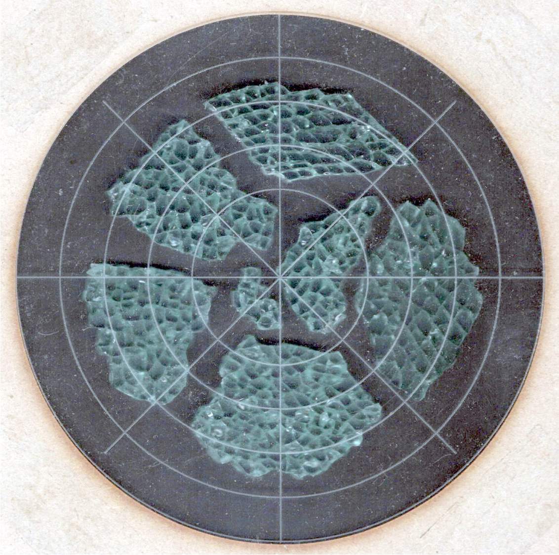
In use, though, it doesn’t look all that bad:
Fragment layout – 5in Set B – scan tweaked
Come to find out those glittery cracks between all the cuboids still confuse GIMP’s edge detection, but at least hand-tracing the outline is easier without all the lines.
The entire “polishing” series as a slideshow for your amusement:
For reasons not relevant here, after Having Been Advised to not walk barefoot on our wood floors, I picked up a pair of beach / pool sandals with comfy soles. Although they have a white logo, they’re black and essentially invisible in the dark when I need them most.
Start by taking a photo of the logo on the clamped-flat upper strap:
UnderArmour logo – flattened
Use GIMP to select the white area, clean it up a little, convert the selection into a path, export it as an SVG file, import into LightBurn, scale to match reality, and Fire The Laser:
UnderArmour logo – GITD tape cutting
That’s a roll of glow-in-the-dark tape which is almost certainly a lethal combination of PVC and phosphorescent stuff, so hold your breath while it cuts.
It’s “actually a “kiss cut” through the tape, but not through the backing paper, letting the whole thing hang together after the operation.
Peel-n-stick on the (still flattened) sandals, expose them to light, and It Just Works:
UnderArmour logo – glowing
The fit isn’t perfect, perhaps due to insufficient flattening, but it’s close enough for my simple needs.
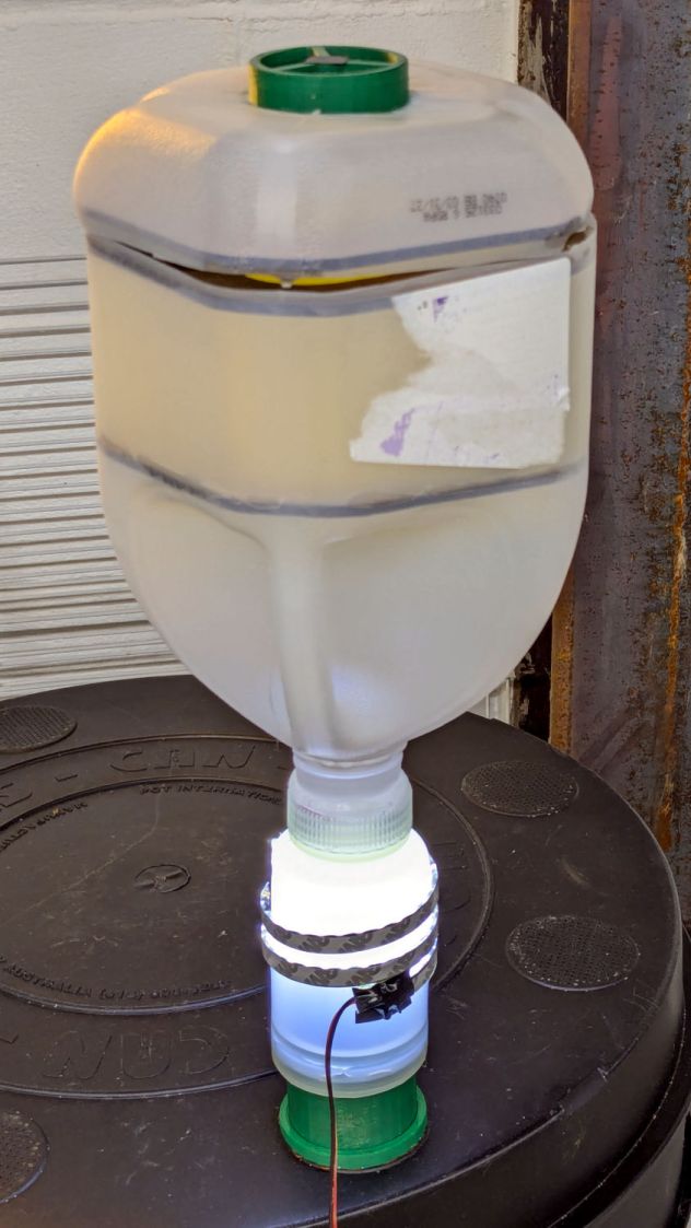
Despite freezing the kitchen scraps going into the worm bin since the previous fruit fly infestation, a zillion flies are now in residence. Lacking the peppermint-stick tube of yesteryear, I conjured another fly trap from common household items:
Worm Bin Fly Trap – overview
The gap around the top got a strip of tape after I took the picture.
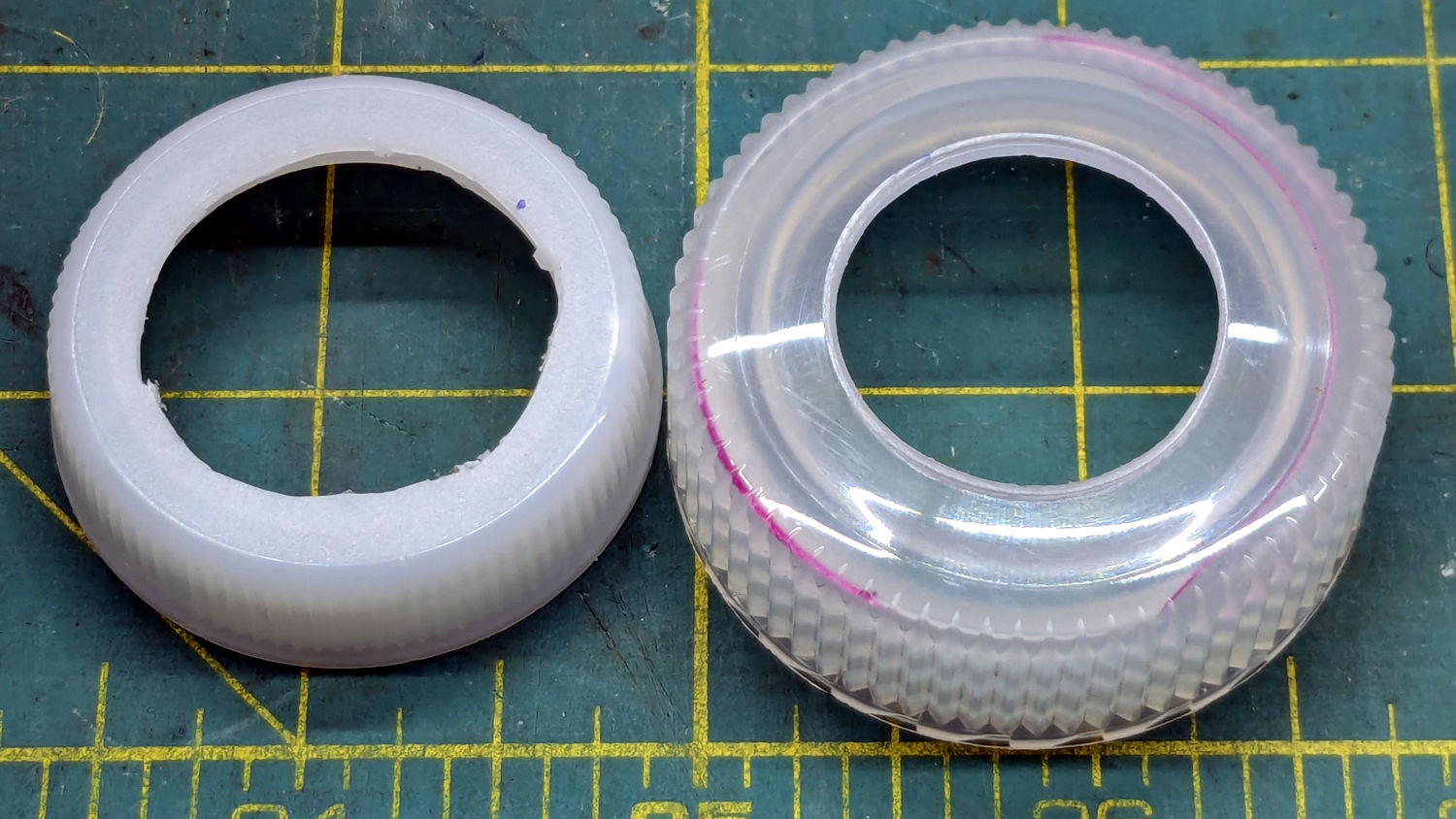
I was all set to 3D print a threaded adapter to join the two bottles when I realized they already had lids. A few minutes of lathe work added a passageway:
Worm Bin Fly Trap – Bottle caps
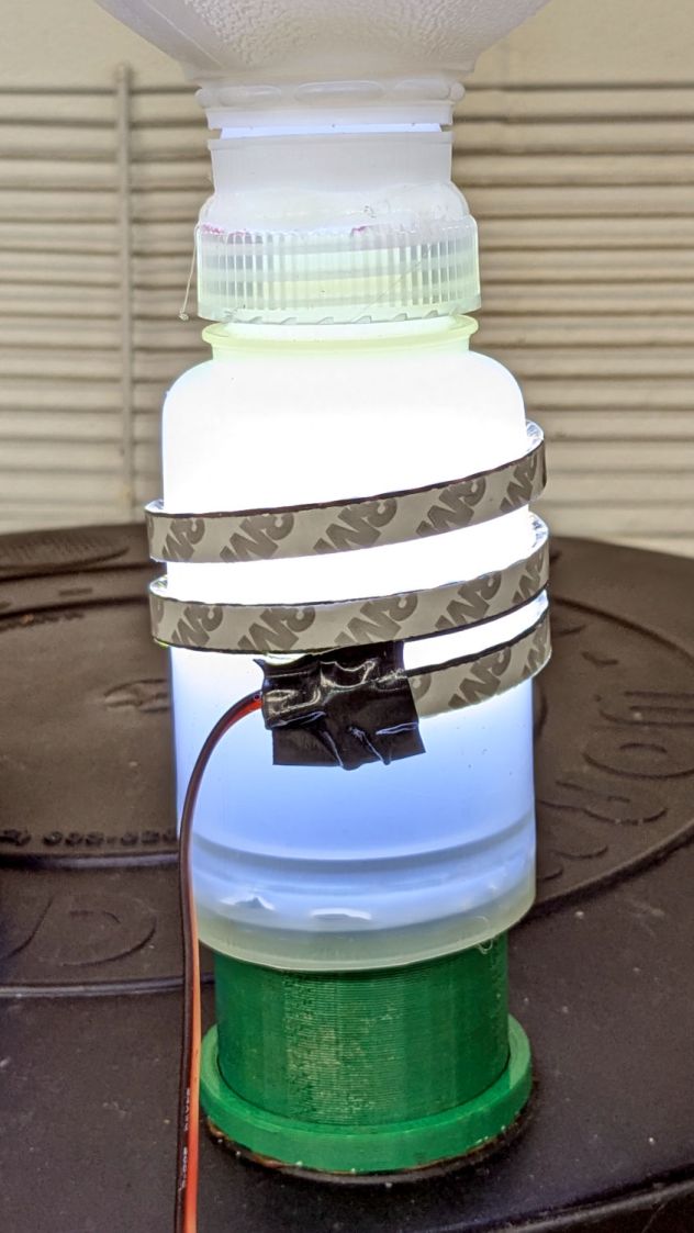
They’re held together by a generous ring of hot melt glue:
Worm Bin Fly Trap – lighting detail
The LED strip provides enough light to simultaneously attract the flies and repel the worms.
The laser cuttery looks like this:
Worm Bin Fly Trap – LightBurn parts
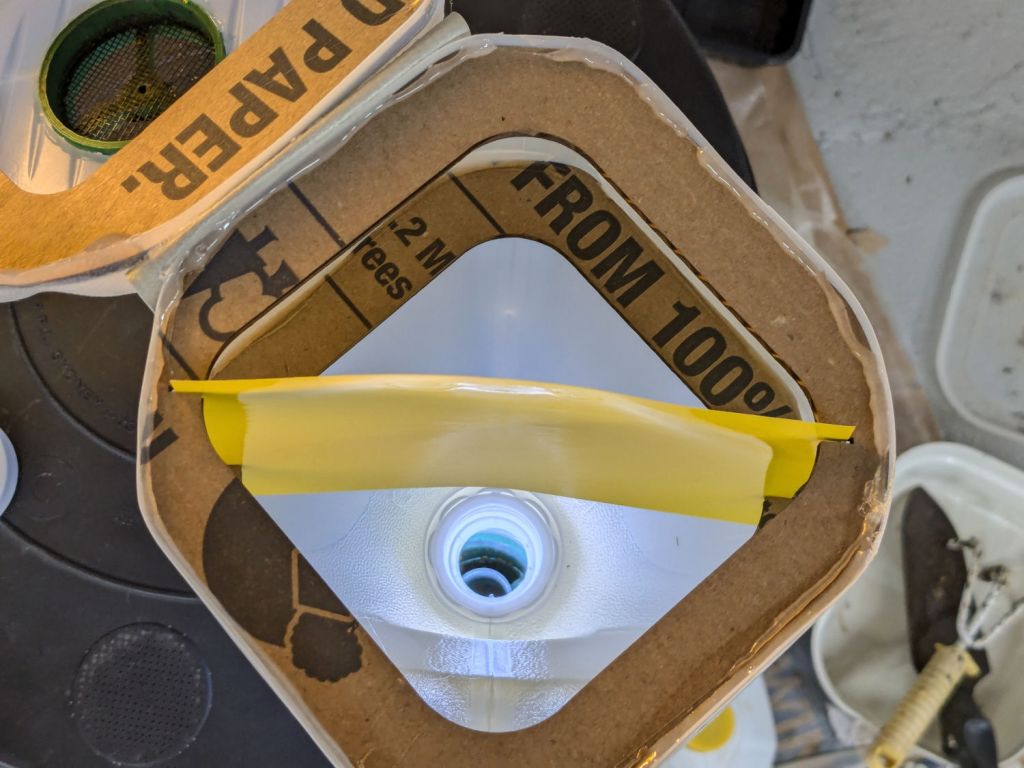
The white shape in the black block is a scan of the cut-open jug, with the other shapes in that row being rectangularized versions. The two tiny notches in the Top and Bottom shapes hold the sticky paper.
The two rings at the top adapt the LED-wrapped bottle to the existing fitting on the worm bin from the previous episode. They’re visible as shadows near the bottom of the bottle.
The circle is a laser-cut hole in the gallon jug bottom for the screened plug made for the pepermint-stick tube; the less said about that operation the better.
So far, so good, although previous experience suggests the flies will be breeding ahead of their (considerable) losses for the next few weeks.
My Fitbit Charge 5 has become fussy about its exact position while snapped to its magnetic charger, so I thought elevating it above the usual clutter might improve its disposition:
FitBit Charge 5 stand – installed
The Charge 5 now snaps firmly onto its charger, the two power pins make solid contact, and it charges just like it used to.
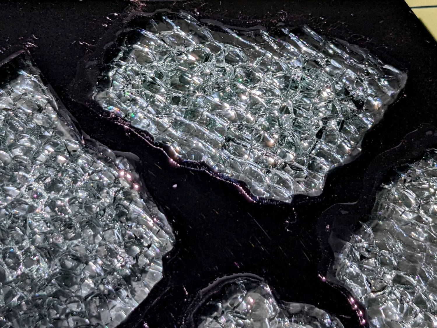
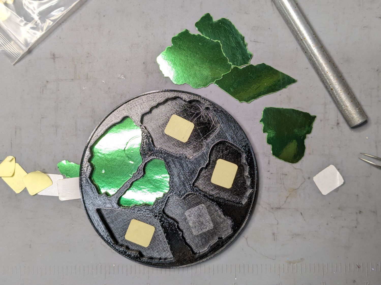
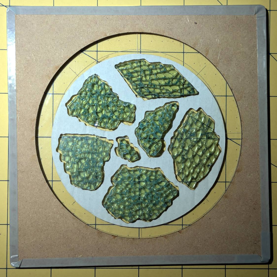
I sprayed the white-ish fragments (on the left) with satin-finish clear rattlecan “paint” in the hopes it would keep epoxy out of the cracks between the glass cuboids and leave the highly reflective air gaps. While it did a reasonable job of sealing, it bonded poorly with the epoxy and produced a dull surface finish.
The unsprayed fragments (on the right) turned out better, although the one in the upper right has a thin air bubble / layer on top. The unsealed cracks between the cuboids show well against the reflective layers, so I think spraying the fragments isn’t worth the effort.
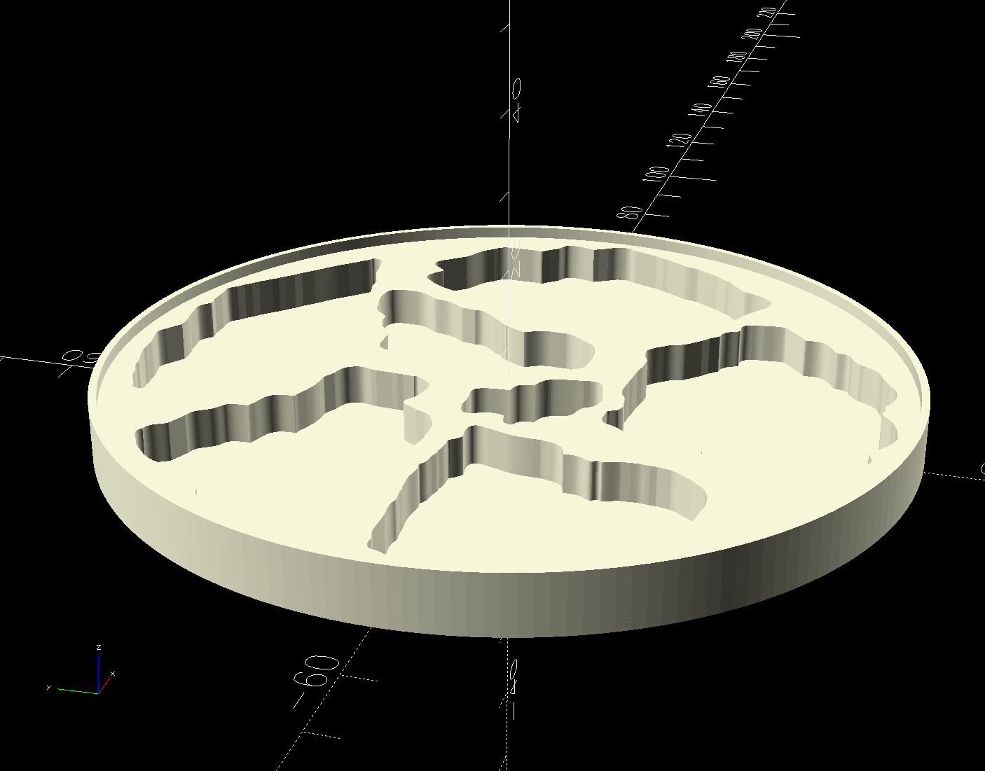
The printed base has a 1 mm tall rim to retain the epoxy:
Printed Coaster Layout – solid model
I mixed enough epoxy to fill half the volume of a disk with the same overall OD and depth (V = h × π × d²/4), which turned out to be barely enough produce a level surface at the rim. There didn’t seem that much epoxy left on the various measuring / mixing cups, but next time I’ll round upward.
Many of the bubbles emerged from below the metalized paper, as well as between the glass and paper, so next time:
Set up a level platform with a sacrificial cover
Omit the adhesive sheet under the metallized paper
Pour a little epoxy into the recesses
Squish the metallized paper into place
Pour more epoxy to cover the paper
Gently squish the glass fragments into place
Ease more epoxy around the fragments
Chivvy the bubbles away
Fill to the rim
The top isn’t exactly flat and has some dull areas, so at some point I want to make it flat with 220 grit sandpaper, work up to some 3000 grit paper I’ve been saving for a special occasion, then finish it off with Novus polish. Which seems like enough hassle to keep the coaster under my sippy cup for a while.
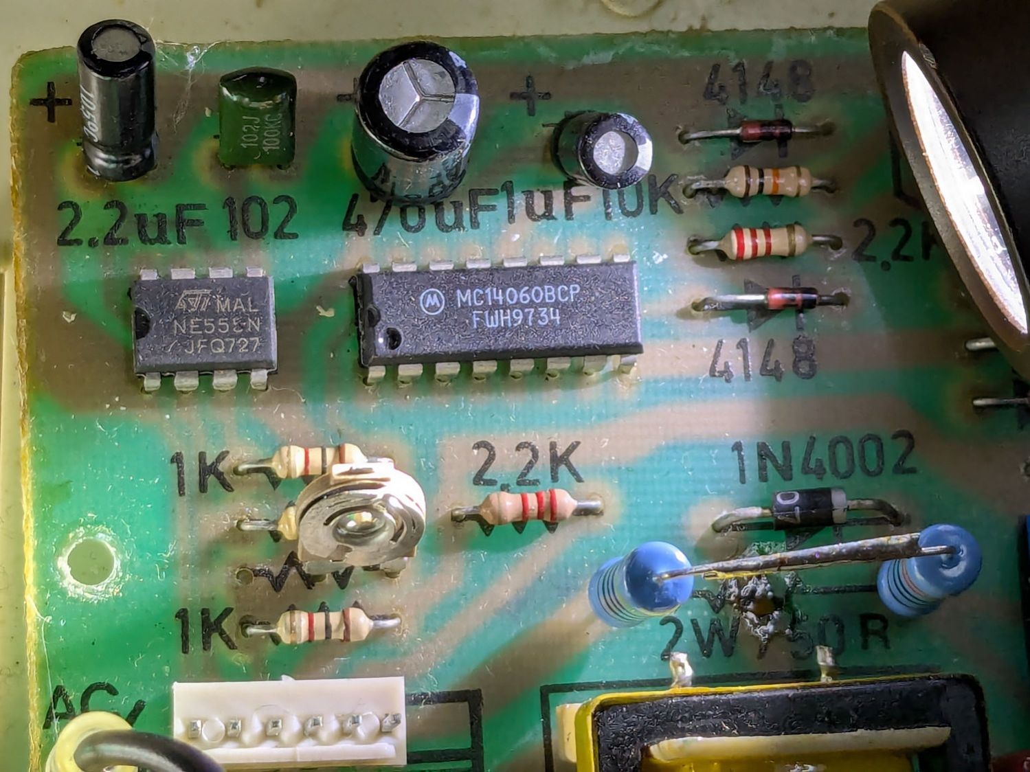
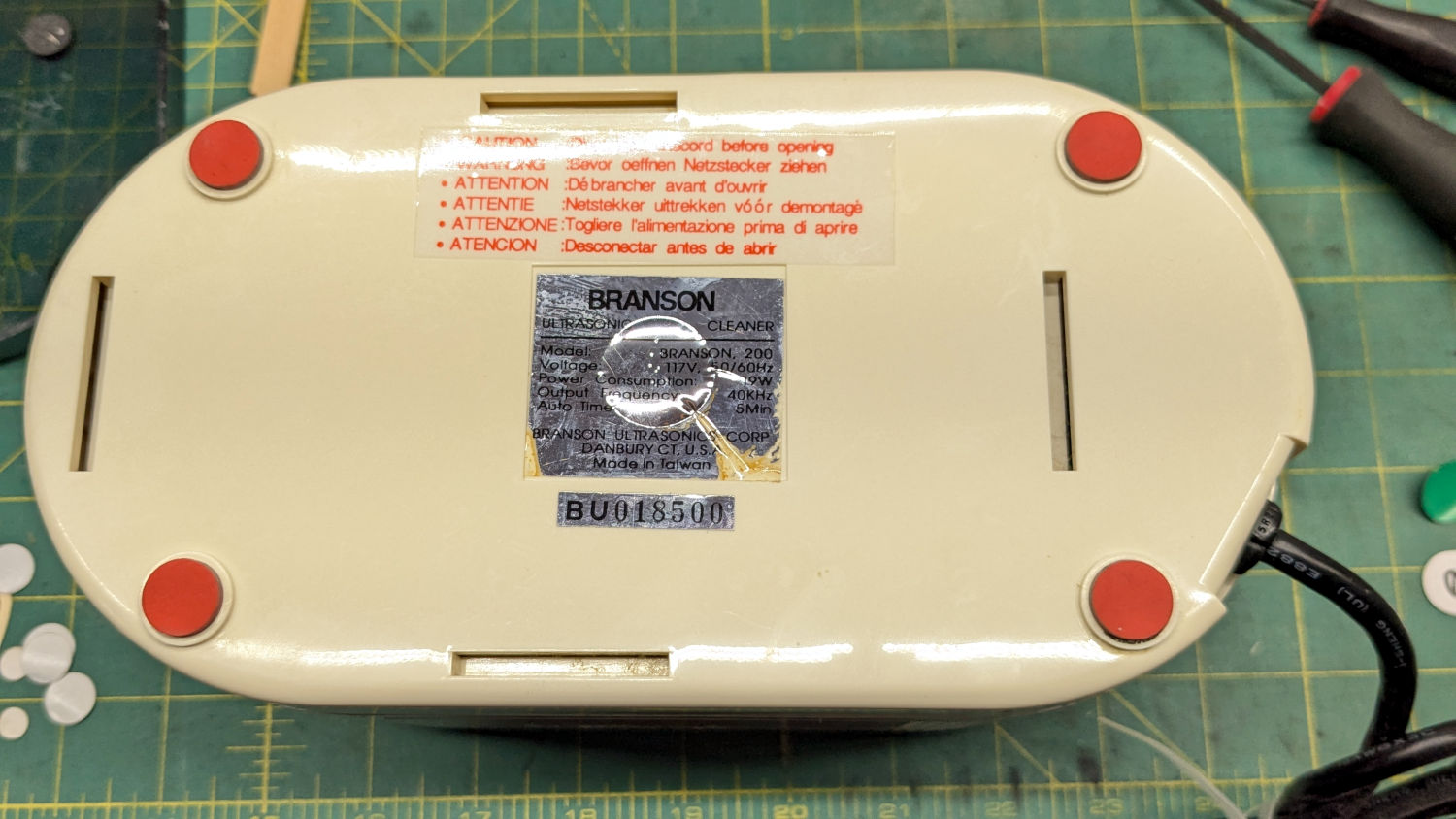
The Branson 200 ultrasonic cleaner in the bathroom has been with me for a long time. If I’m reading the IC date codes correctly, it’s one of the first things I bought after real paychecks began arriving back in 1974:
Branson 200 ultrasonic cleaner – IC date codes
The circuit board has that spacious old-time layout:
Branson 200 ultrasonic cleaner – PCB overview
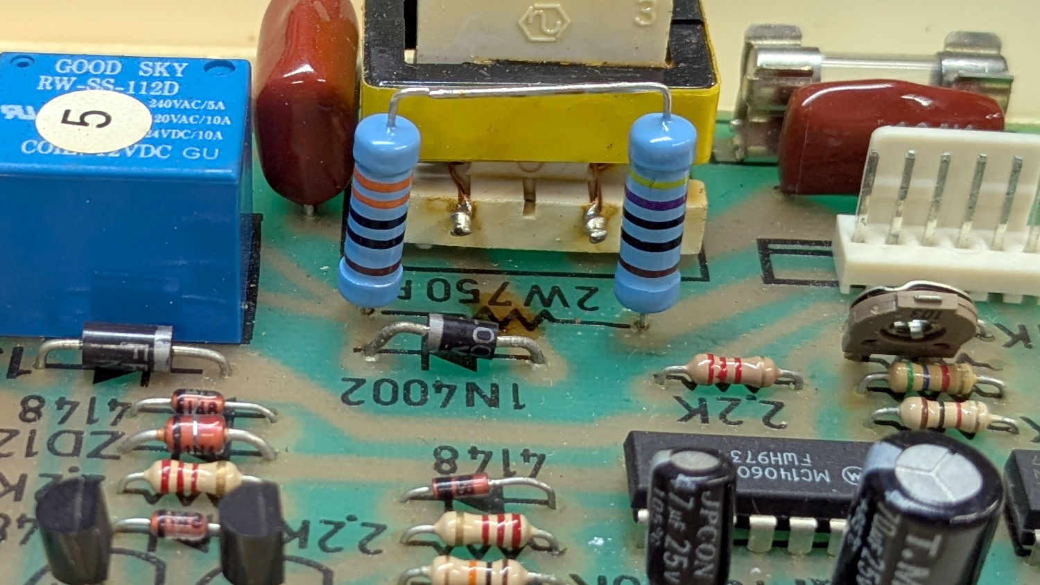
Believe it or not, this isn’t why I took the thing apart:
Branson 200 ultrasonic cleaner – charred resistor
I’ve never seen a PCB with the component values printed on it, but they definitely came in handy!
That resistor measured 743 Ω: still good, even with an extra-crispy coating.
Assuming it was dissipating a bit more than its 2 W rating could handle, I replaced it with a 470 Ω + 330 Ω series combination of 2 W 1% metal film resistors:
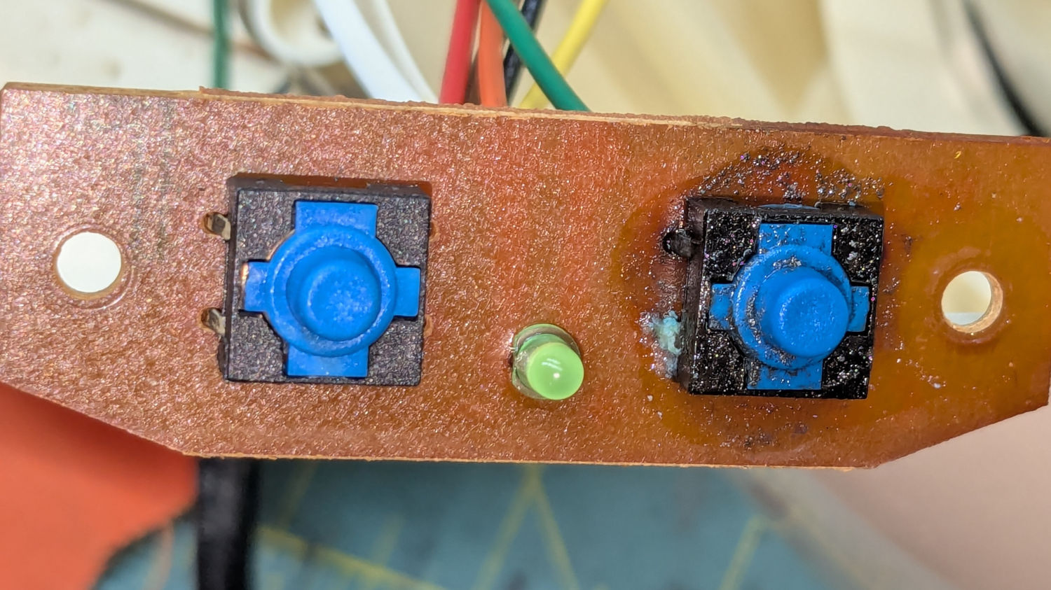
Branson 200 ultrasonic cleaner – retrofit resistors – top
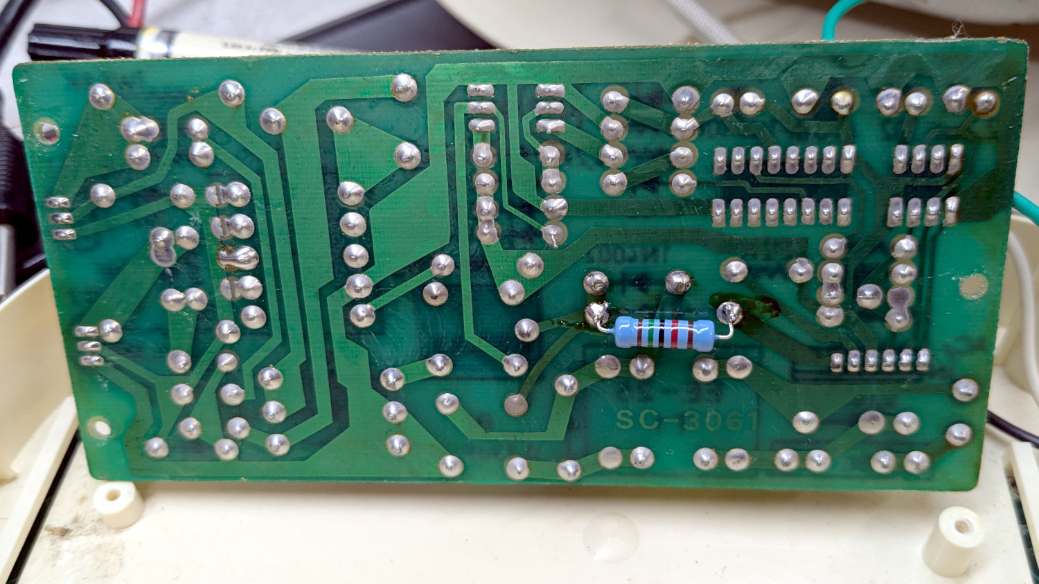
In parallel with a 15 kΩ resistor on the back of the PCB to bring them down to 759 Ω:
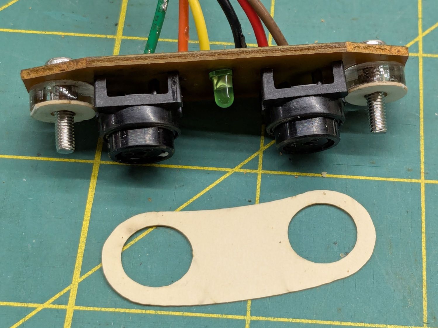
Well, almost perfectly. The original case holes were a snug fit around a 25/64 inch = 9.8 mm drill , so I hand-twisted X and Y drills (10.1 and 10.3 mm, respectively) to embiggen the holes for a loose fit around the new switches.
The two small plastic disks + paper shims hold the PCB just far enough away from the case to put the switch actuators flush with the case surface, with 12 mm M3 SHCS replacing the original 6 mm screws.
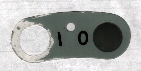
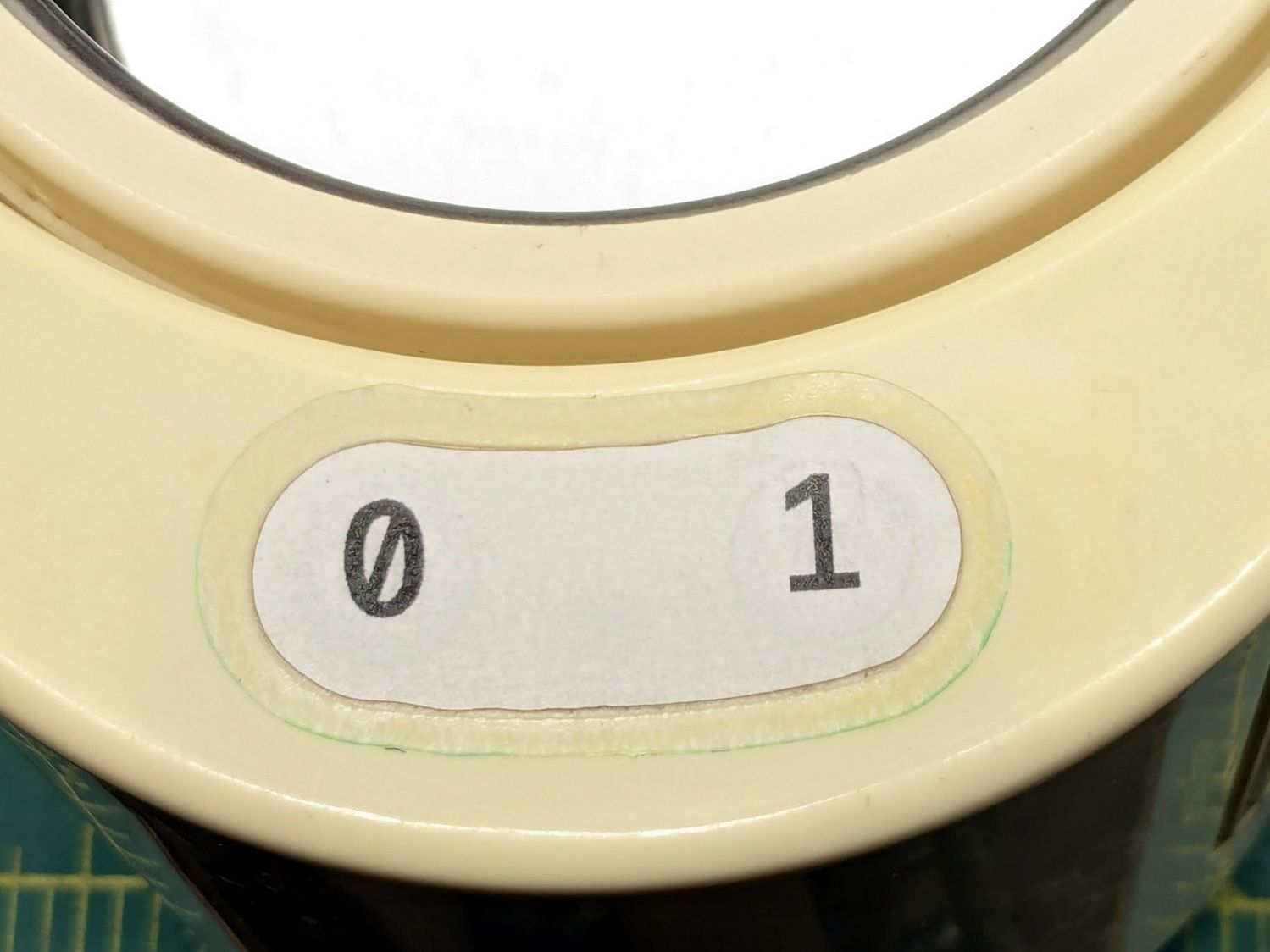
The cardboard test piece came from the usual scan of the original switch cover and, after a few iterations, we now have a stylin’ paper replacement:
The transparent cover with greenish edges is transfer tape intended for vinyl sheets, which will likely not survive very long at all. It’s outset 3 mm from the paper label, just barely enough to get any traction at all on the case.
While I was at it, I replaced the worn black rubber feet with fancy red stamp-pad rubber feet:
For the record, only two screws secure the top & bottom parts of the case. They’re on the power-cord end of the bottom, so those are the only two feet you must peel off to get inside.
All of which put the cleaner back in operation while I figure out what kind of tape will seal the power switches more permanently.
The motivation for making Yet Another Coaster was to see if combining a few techniques I’ve recently learned would produce a nicer result.
Spoiler: Yup, with more to be learned and practiced.
This is a somewhat nonlinear narrative reminding me of things to do and not do in the future, so don’t treat it as a direct how-to set of instructions.
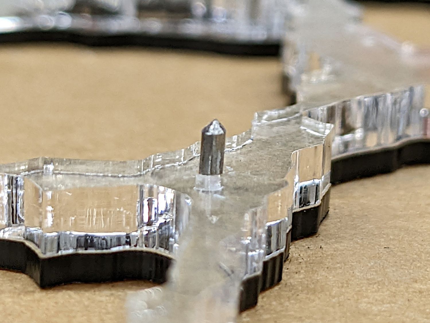
The glass fragments sit inside holes in the next two (or three or whatever) acrylic layers, which must have a total thicknesses slightly more than the glass thickness andremain properly aligned while assembling the whole stack:
Smashed Glass Coaster 5 – alignment pin
Bonus: all that cutting generates an absurd amount of acrylic scrap. I eventually put much of it to good use, but not producing it in the first place would be a Good Thing …
So 3D print the entire base, which requires generating a solid model with recesses for the fragments:
Printed Coaster Layout – solid model
Because there’s no real justification for an optical-quality mirror under smashed glass, use reflective metallized paper in the recesses as reflectors:
Smashed glass printed coaster – metallized paper assembly
The glass is more-or-less greenish-blueish, so I used a strip of green metallized paper that made the glass fragments green. Obviously there’s some room for choice down there.
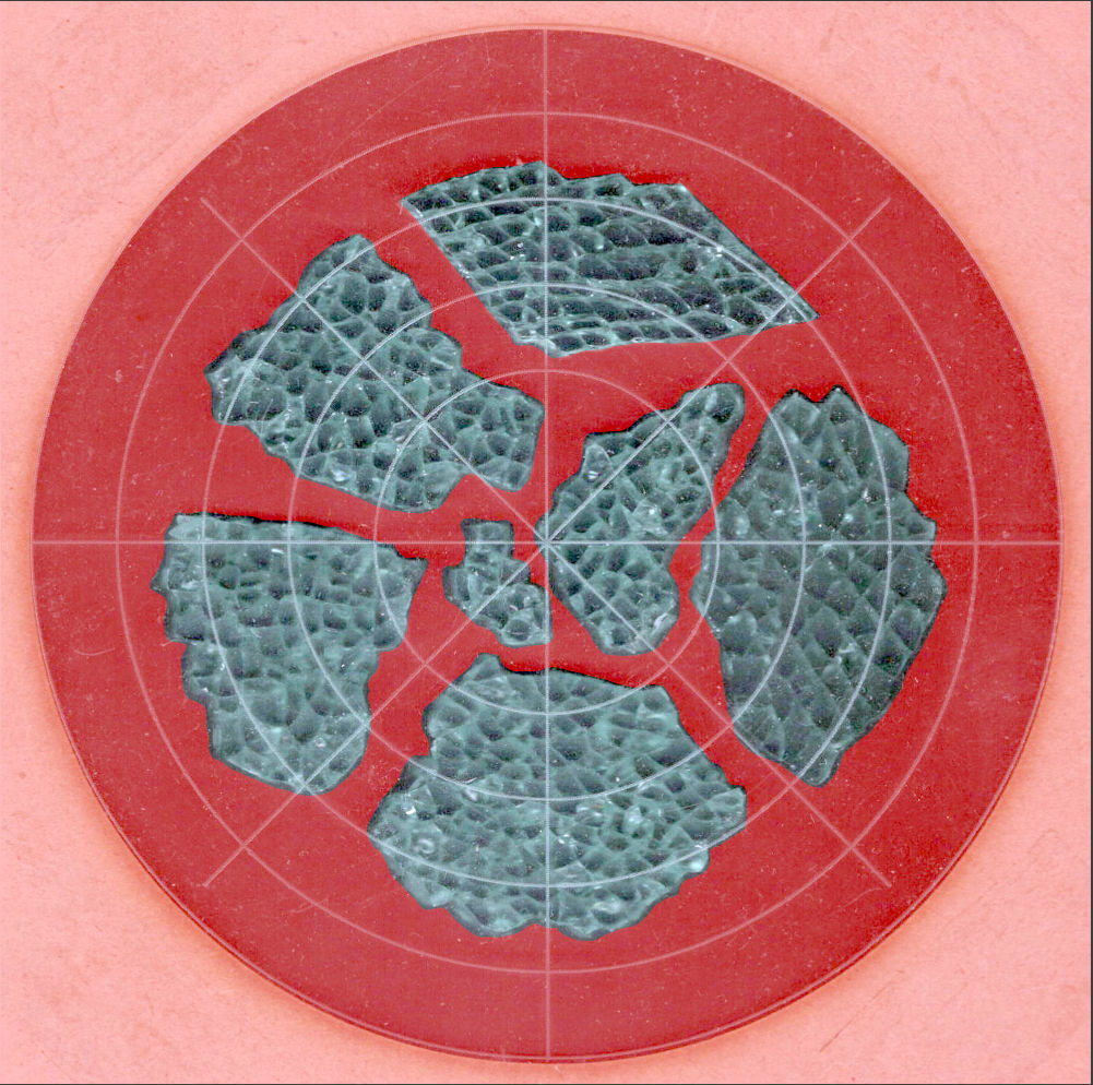
Both the base and the reflectors use outlines of the fragments, so I started with a scan of the approximate layout in GIMP:
Smashed Glass – 4in – group A – tweaked
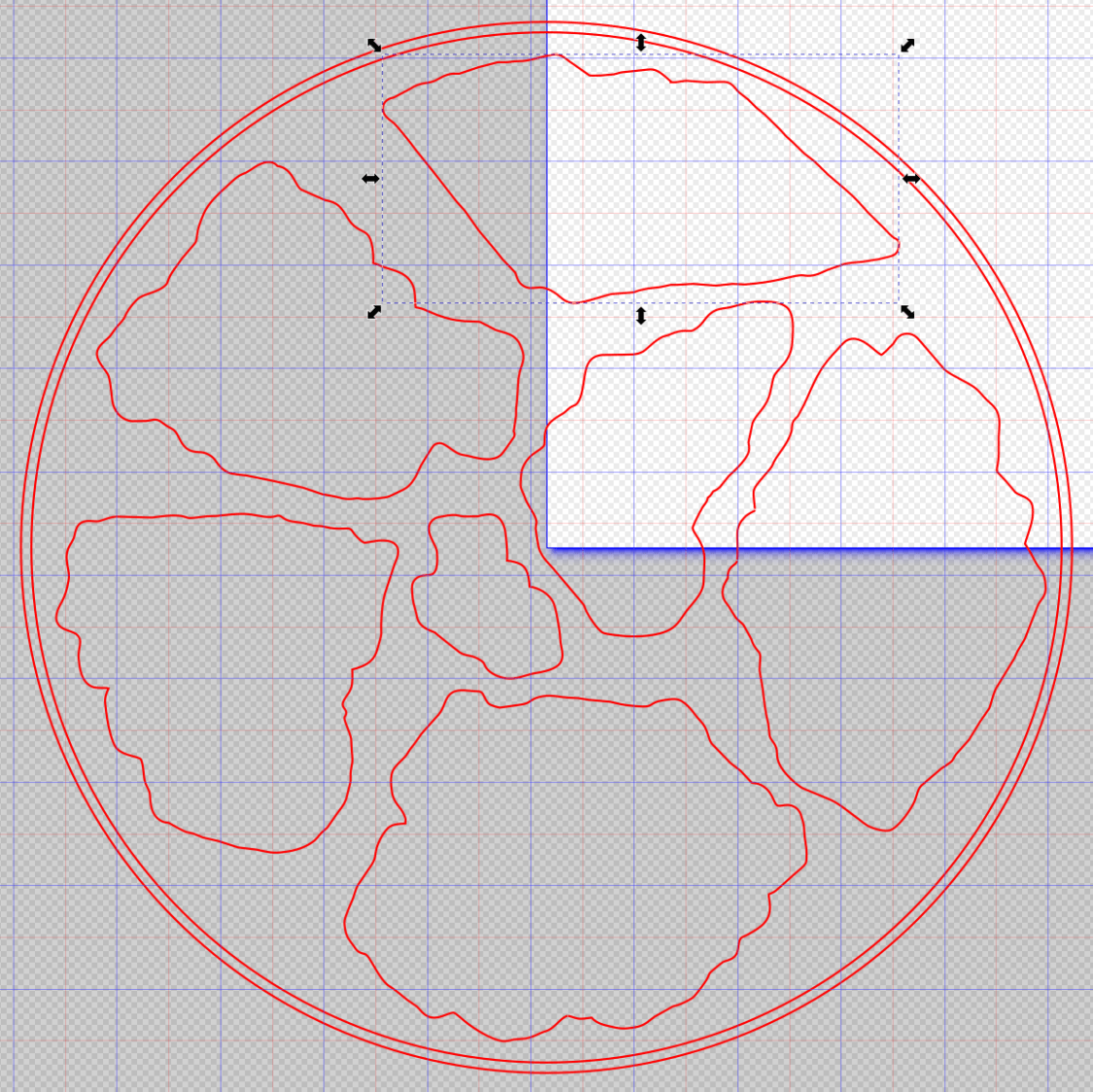
I traced the outline of each fragment using the Scissors Select Tool, which lays line segments along the sharpest gradient between clicked points, then switched into Quick Mask mode to adjust & smooth the results:
Smashed Glass paths – quick mask
That’s the result after sketching & saving all the paths as separate SVG files to allow importing them individually into InkScape, OpenSCAD, and LightBurn.
Which turned out to be suboptimal, as it let me write an off-by-one blooper omitting the last file from the OpenSCAD model:
A better choice puts all the paths into a single named group, saved as a single SVG file, then importing that group from the file using its name, along these lines:
It’s not clear if I can do that directly from GIMP by saving all the paths in a single file, then importing that lump into Inkscape as a group, but it’ll go something like that.
After getting the fragment paths into Inkscape, add a 0.5 mm offset to each path to clear any non-vertical edges. This will be checked with the template cut using LightBurn as described below.
Add a 1 mm rim around the outside, with the 4 inch OD matching the usual PSA cork base:
Fragment layout – 4in
Now’s the time to nudge / rotate the outlines so they have at least a millimeter of clearance on all sides / ends, because that’s about as thin a section of printed plastic as you want.
Locating the center of the OD (and, thus, everything inside) at the lower-left corner of the Inkscape page will put them at the OpenSCAD origin. I have set Inkscape to have its origin at the lower left, rather than the default upper left, so your origin may vary.
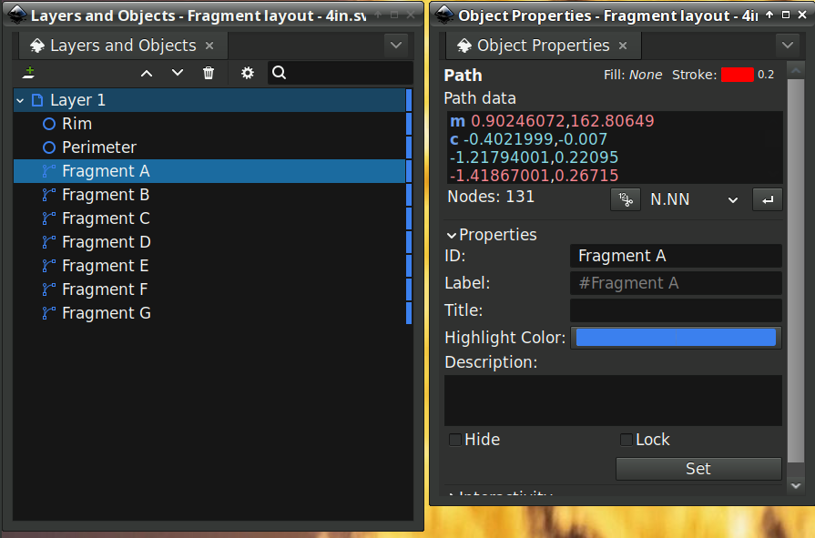
Select one of the paths:
Fragment layout – Inkscape A
Then set the ID in its Object Properties:
Fragment layout – Inkscape A – properties
There is an interaction between the name over in the Layers and Objects window, which apparently comes from the GIMP path name for the imported fragments, and the resulting ID and Label in the Object Properties window. However, renaming an object on the left, as for the Rim and Perimeter circles, does not set their ID or Label on the right. Obviously, I have more learning to do before this goes smoothly.
With everything laid out and named and saved in an SVG file, the OpenSCAD program is straightforward (and now imports all the fragments):
Which squirts out the solid model appearing above.
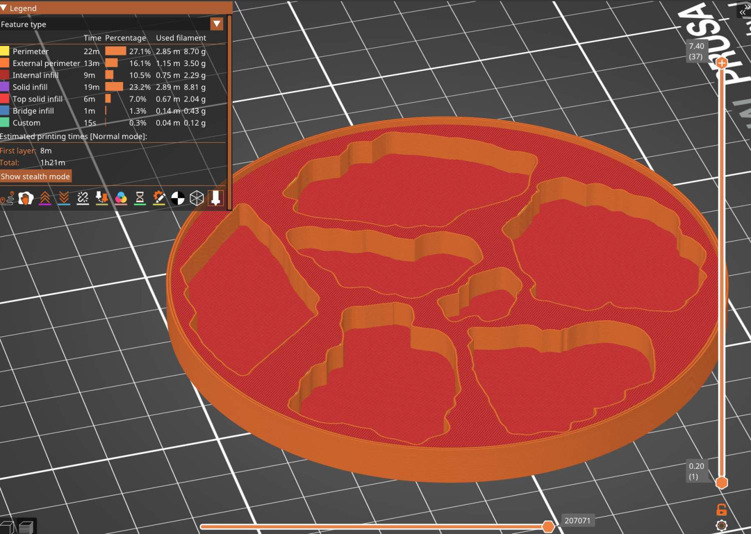
Feeding it into PrusaSlicer turns the model into something printable:
Printed Coaster Layout – slicer
And after supper I had one in my hands.
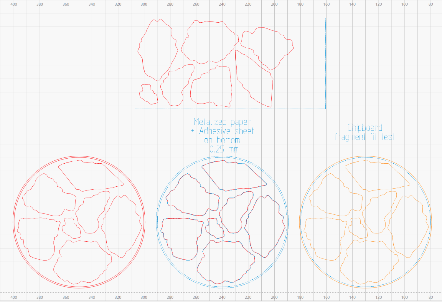
Before doing that, however, import the same SVG file into LightBurn, as on the left:
Printed Coaster Layout – LightBurn
On the right, duplicate it, put the inner Rim on a tool layer, put the rest on a layer set to cut chipboard, and make a template to verify those holes fit around the fragments:
Smashed glass printed coaster – fragment test fit
Which a few didn’t, explaining why I go to all that trouble. Iterate through GIMP → paths → SVG → Inkscape → LightBurn until it’s all good. Obviously, you do this before you get too far into OpenSCAD, but they all derive from the Inkscape layout, so there’s not a lot of wasted motion.
The middle LightBurn layout insets the fragment outlines by 0.25 mm to ensure the paper fits easily and puts them on a layer set to cut metallized paper. Those fragments then get duplicated and rearranged within the rectangle on the top to fit a strip of metallized paper from the scrap box. Fire The Laser to cut them out and stick them to the bottom of their corresponding 3D printed recesses with leftover snippets of craft adhesive sheet as shown above.
I had originally intended to cover the bottom of the entire sheet of metallized paper with an adhesive sheet, but realized the whole affair was going to be submerged in epoxy, so just making sure the paper didn’t float away would suffice.