Ed Nisley's Blog: Shop notes, electronics, firmware, machinery, 3D printing, laser cuttery, and curiosities. Contents: 100% human thinking, 0% AI slop.
Tag: Improvements
Making the world a better place, one piece at a time
It turns out that the outer diameter of CD platters isn’t quite as perfectly controlled as you (well, I) might imagine, although the differences between CDs from different sources amounts to perhaps ±0.1 mm. Of course, instantly after putting the tape-down fixture into use, the next few discs atop my stack of scrap CDs were just large enough to not quite fit.
The Sherline’s workspace can’t maneuver the holder’s perimeter around the spindle, so embiggening the OD calls for the rotary table. The general idea is to clamp the center of the fixture to the rotary table, run a small end mill about 0.1 mm into the fixture’s OD, spin the table one revolution, and be done with it.
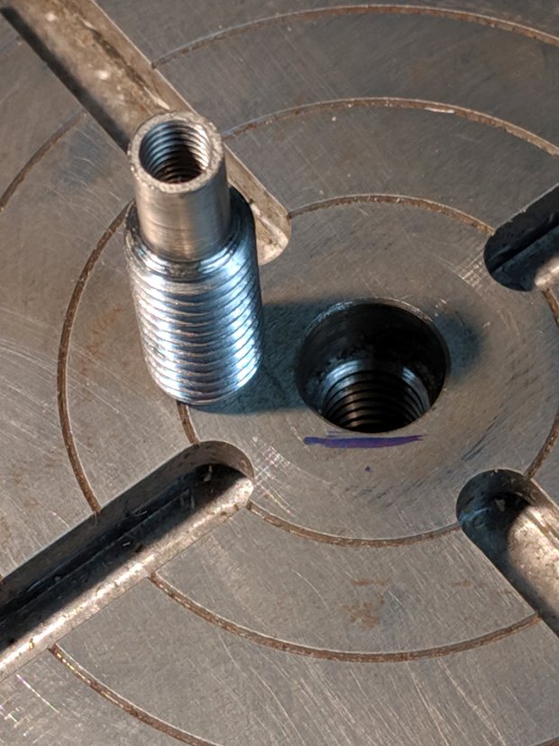
Of course, the rotary table’s 3/8-16 threaded center hole doesn’t match the fixture’s 6 mm center hole: we need an adapter. Start with a 1 inch long 3/8-16 stainless steel hex bolt, center drill the end, peel off the hex head, then turn to 6 mm OD, going down far enough so the threads don’t stick up out of the table too much:
CNC 3018-Pro – CD fixture milling – bolt turning
The Sherline uses 10-32 screws, so poke a #16 drill 15 mm into the bolt to get maybe 25% thread depth (because it’s a blind hole into stainless steel for an application requiring minimal strength and I hate breaking taps), tap 10-32, clean out the hole, and call it All Good:
CNC 3018-Pro – CD fixture milling – rotary table adapter
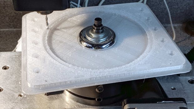
Find the trim plate from an old faucet to reach around the central boss, stack up enough flat washers to meet the nut, snug a Sherline spherical nut + washer set (because it’s within reach), chuck up a 1/8 inch mill, and have at it:
CNC 3018-Pro – CD fixture milling
The fixture sits atop an aluminum plate cut to fit a smaller version of the table riser, but this requires zero fancy alignment. The 6 mm adapter centers the fixture on the rotary table and the cutter sits at a fixed radius from the center wherever it contacts the fixture rim; just spin the table and it cuts a neatly centered circle.
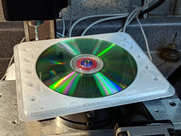
A test fit showed the oversize discs fit perfectly:
Which looks exactly as you think it would in real life:
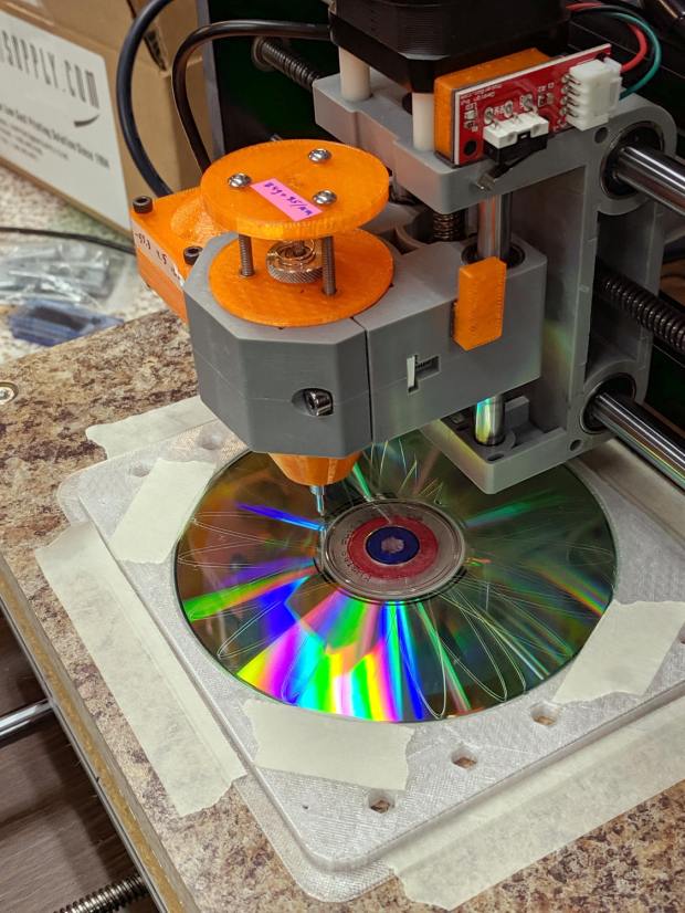
CNC 3018-Pro – CD fixture – taped
Admittedly, masking tape doesn’t look professional, but it’s low-profile, cheap and works perfectly. Blue painter’s tape for the “permanent” hold-down strips on the platform would be a colorful upgrade.
It’s centered on the platform at the XY=0 origin in the middle of the XY travel limits, with edges aligned parallel to the axes. Homing the 3018 and moving to XY=0 puts the tool point directly over the center of the CD without any fussy alignment.
The blue-and-red rings around the center hole assist probe camera alignment, whenever that’s necessary.
This file contains hidden or bidirectional Unicode text that may be interpreted or compiled differently than what appears below. To review, open the file in an editor that reveals hidden Unicode characters.
Learn more about bidirectional Unicode characters
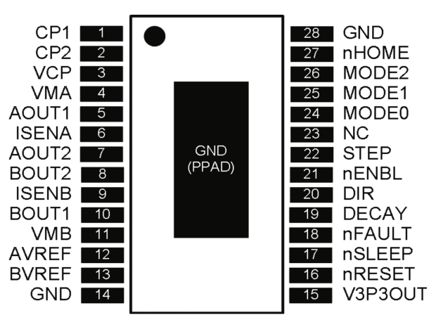
The DRV8825 stepper driver chip has a -Home output going active during the (micro)step corresponding to 45°, where both winding currents equal 71% of the peak value:
DRV8825 pinout
Unfortunately, pin 27 is another unconnected pin on the DRV8825 PCB, without even a hint of a pad for E-Z soldering.
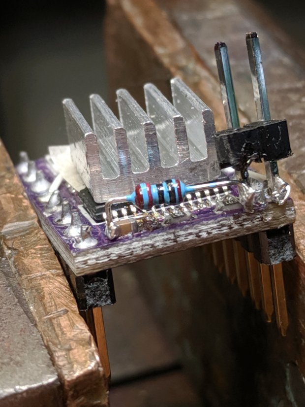
It’s also an open-drain output in need of a pullup, so I globbed on a 1/8 W 10 kΩ resistor in addition to the tiny wire from the IC pad to the left header pin:
DRV8825 PCB – Home signal output
Read it from the right: brown black black red gold. Even in person, the colors don’t look like that, not even a little bit: always measure before installation!
The right header pin is firmly soldered to the PCB ground pin I also used for the 1:8 microstep hack. The whole affair received a generous layer of hot melt glue in the hope of some mechanical stabilization, although hanging a scope probe off those pins can’t possibly end well.
The general idea is to provide a scope sync output independent of the motor speed, so I can look at the current waveforms:
3018 X – Fast – 12V – 140mm-min 1A-div
The alert reader will note the pulse occurs on the down-going side of the waveforms, which means I have the current probes clipped on backwards or, equivalently, on the wrong wire. The point is to get a stable sync, so it’s all good no matter which way the current goes.
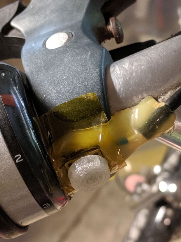
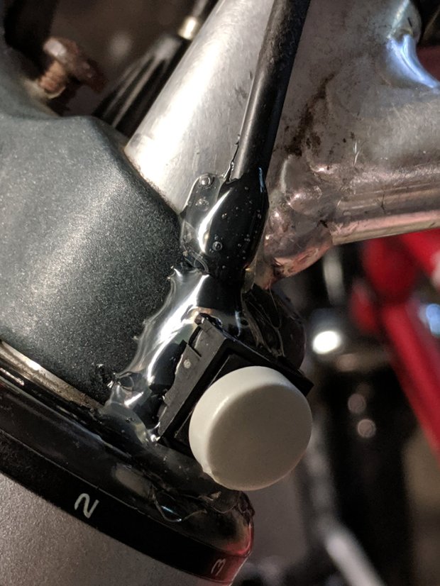
It’s been sitting there for least five years, as witnessed by the sun-yellowed hot melt glue blob, which is pretty good service from a switch intended for indoor use. The 3D printed button never fell off and, in fact, was difficult to remove, so that worked well.
I took it apart and cleaned the contacts, but to no avail, so her bike now sports a new switch with a similar rounded dome:
Tour Easy – new PTT switch
I clipped the wires a bit beyond the terminals and soldered the new switch in place, so it’s the same cable as before.
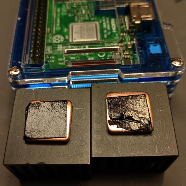
Unfortunately, the thermal tape on one of the CPU heatsinks was sufficiently wrinkled to prevent good contact with the CPU:
RPi taped heatsinks – as received
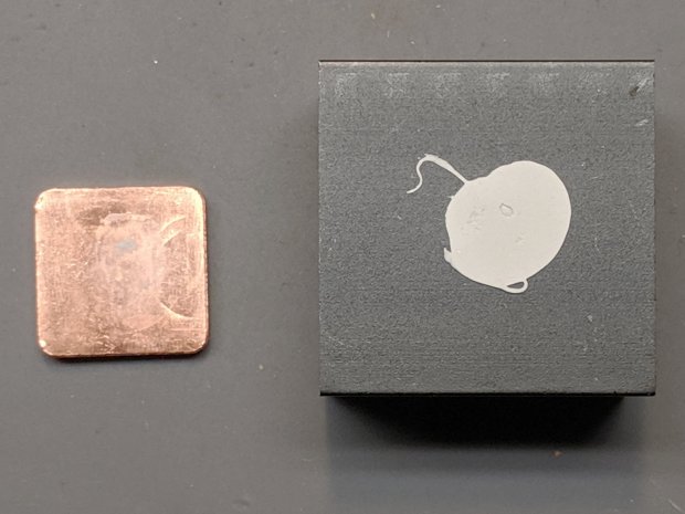
The seller sent a replacement copper slug with tape on one side. Presumably, they glue it to the heatsink with thermal silicone:
Moster RPi Heatsink – silicone adhesive
Of which, I have none on hand.
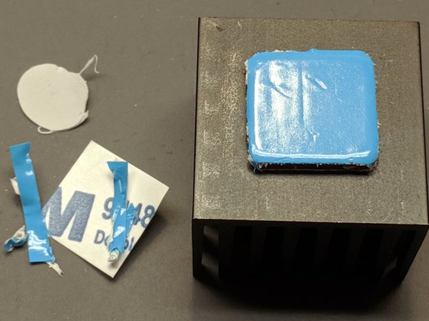
So I did what I should have done originally, which was to drop a few bucks on a lifetime supply of thermally conductive heatsink tape, apply it to the bare side of the slug and stick the slug to the heatsink with their tape:
Moster RPi Heatsink – replacement adhesive tape
The blue stuff is the separation film, with the tape being white. It doesn’t match the black tape on the other side, but seems gooey enough to work.
Done!
Despite the heatsink hype, ball grid array chips dissipate most of their heat through their pads (and perhaps a central thermal pad) into the PCB, so sticking a heatsink atop the package is largely decorative, along the lines of hotrod ornamentation.
The epoxy packages used in previous Raspberry Pi iterations had better thermal conductivity to their top surface:
RPi 3 B – epoxy CPU
Than the more recent metal-top packages, which surely have inert-gas fill under the lid:
Yes, the heatsink does conduct some heat into the air, even if not nearly as much as you might want.
(*) I’m pretty sure “Moster” was a typo in the original eBay listing which took on a life of its own to become something of an unofficial trademark. All of the search results ship from Duluth, Georgia (USA), regardless of the nominal seller; feel free to draw your own conclusions.
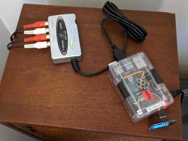
Fiddle with the amp to select the phonograph, poke the TAPE 2 button to send audio to/from the UCA202, fire up an SSH session, kill the streaming audio program, and figure out what audio hardware is out there:
$ arecord -l
**** List of CAPTURE Hardware Devices ****
card 1: CODEC [USB Audio CODEC], device 0: USB Audio [USB Audio]
  Subdevices: 1/1
  Subdevice #0: subdevice #0
Not much else to choose from on a Raspberry Pi, so see what the UCA202 can do:
Given those limited choices, 16 bit little-endian at 48 kHz seems like a no-brainer.
Find out all the ALSA device names:
$ arecord -L
null
    Discard all samples (playback) or generate zero samples (capture)
sysdefault:CARD=CODEC
    USB Audio CODEC, USB Audio
    Default Audio Device
front:CARD=CODEC,DEV=0
    USB Audio CODEC, USB Audio
    Front speakers
surround21:CARD=CODEC,DEV=0
    USB Audio CODEC, USB Audio
    2.1 Surround output to Front and Subwoofer speakers
surround40:CARD=CODEC,DEV=0
    USB Audio CODEC, USB Audio
    4.0 Surround output to Front and Rear speakers
surround41:CARD=CODEC,DEV=0
    USB Audio CODEC, USB Audio
    4.1 Surround output to Front, Rear and Subwoofer speakers
surround50:CARD=CODEC,DEV=0
    USB Audio CODEC, USB Audio
    5.0 Surround output to Front, Center and Rear speakers
surround51:CARD=CODEC,DEV=0
    USB Audio CODEC, USB Audio
    5.1 Surround output to Front, Center, Rear and Subwoofer speakers
surround71:CARD=CODEC,DEV=0
    USB Audio CODEC, USB Audio
    7.1 Surround output to Front, Center, Side, Rear and Woofer speakers
iec958:CARD=CODEC,DEV=0
    USB Audio CODEC, USB Audio
    IEC958 (S/PDIF) Digital Audio Output
dmix:CARD=CODEC,DEV=0
    USB Audio CODEC, USB Audio
    Direct sample mixing device
dsnoop:CARD=CODEC,DEV=0
    USB Audio CODEC, USB Audio
    Direct sample snooping device
hw:CARD=CODEC,DEV=0
    USB Audio CODEC, USB Audio
    Direct hardware device without any conversions
plughw:CARD=CODEC,DEV=0
    USB Audio CODEC, USB Audio
    Hardware device with all software conversions
They all point to the same hardware, so AFAICT the default device will work fine.
Try recording something directly to the RPi’s /tmp directory, using the --format=dat shortcut for “stereo 16 bit 48 kHz” and --mmap to (maybe) avoid useless I/O:
$ arecord --format=dat --mmap --vumeter=stereo --duration=$(( 30 * 60 ))  /tmp/Side\ 1.wav
Recording WAVE '/tmp/Side 1.wav' : Signed 16 bit Little Endian, Rate 48000 Hz, Stereo
                                  +02%|01%+                                   overrun!!! (at least 1.840 ms long)
                                  +02%|02%+                                   overrun!!! (at least 247.720 ms long)
                                +# 07%|06%##+                                 overrun!!! (at least 449.849 ms long)
                                 + 03%|02%+                                   overrun!!! (at least 116.850 ms long)
Huh. Looks like “writing to disk” sometimes takes far too long, which seems to be the default for MicroSD cards.
The same thing happened over NFS to the file server in the basement:
$ arecord --format=dat --mmap --vumeter=stereo --duration=$(( 30 * 60 ))  /mnt/part/Transfers/Side\ 1.wav

Recording WAVE '/mnt/part/Transfers/Side 1.wav' : Signed 16 bit Little Endian, Rate 48000 Hz, Stereo

                               +   09%|07%  +                                 overrun!!! (at least 660.372 ms long)

                                +# 08%|06%# +                                 overrun!!! (at least 687.906 ms long)
So maybe it’s an I/O thing on the RPi’s multiplexed / overloaded USB + Ethernet hardware?
Trying a USB memory jammed into the RPi, under the assumption it might be better at recording than the MicroSD Card:
$ arecord --format=dat --mmap --vumeter=stereo --duration=$(( 30 * 60 ))  /mnt/part/Side\ 1.wav
Recording WAVE '/mnt/part/Side 1.wav' : Signed 16 bit Little Endian, Rate 48000 Hz, Stereo
                                  +01%|01%+                                   overrun!!! (at least 236.983 ms long)
Well, if it’s overrunning the default buffer, obviously it needs Moah Buffah:
$ arecord --format=dat --mmap --vumeter=stereo --buffer-time=1000000 --duration=$(( 30 * 60 ))  /mnt/part/Side\ 1.wav
Recording WAVE '/mnt/part/Side 1.wav' : Signed 16 bit Little Endian, Rate 48000 Hz, Stereo
                               +## 10%|06%# +                                 overrun!!! (at least 359.288 ms long)
When brute force doesn’t work, you’re just not using enough of it:
$ arecord --format=dat --mmap --vumeter=stereo --buffer-time=2000000 --duration=$(( 30 * 60 ))  /mnt/part/Side\ 1.wav
Recording WAVE '/mnt/part/Side 1.wav' : Signed 16 bit Little Endian, Rate 48000 Hz, Stereo
                                  +00%|00%+
Sampling four bytes at 48 kHz fills 192 kB/s, so a 2 s buffer blots up 384 kB, which seems survivable even on a Raspberry Pi.
The audio arrives at 11.5 MB/min, so an LP side with 20 min of audio will require about 250 MB of disk space. The USB memory was an ancient 2 GB card, so all four sides filled it halfway:
$ ll /mnt/part
total 1.1G
drwxr-xr-x  2 ed   root 4.0K Dec 31  1969  ./
drwxr-xr-x 17 root root 4.0K Jun  7 19:15  ../
-rwxr-xr-x  1 ed   root 281M Sep  1 14:38 'Side 1.wav'*
-rwxr-xr-x  1 ed   root 242M Sep  1 15:01 'Side 2.wav'*
-rwxr-xr-x  1 ed   root 265M Sep  1 15:27 'Side 3.wav'*
-rwxr-xr-x  1 ed   root 330M Sep  1 15:58 'Side 4.wav'*
Side 4 is a bit longer than the rest, because I was folding laundry and the recording stopped at the 30 minute timeout after 10 minutes of silence.
Now, to load ’em into Audacity, chop ’em into tracks, and save the lot as MP3 files …
With the 3018-Pro used for drag engraving on CDs and hard drive platters, there’s no need for all the clearance below the Z-axis carriage required for the OEM motor and ER11 collet chuck. A chunk of laminate countertop and a hunk of Celotex foam insulation produce a nicely flat surface 47 mm above the platform:
CNC 3018 Table Riser
It’s surprisingly flat:
Table Flatness Measurement – 2019-08-30
Those are millimeters of clearance between the gray plastic clamp around the diamond drag tool holder (about which, more later) and my trusty bench block, measured at 50 mm intervals across the platform. The lower figures appeared after tightening the upper-left screw by a little over 1/6 turn = 0.2 mm, making the entire platform flat & aligned within ±0.1 mm.
Yeah, not bad for a scrap countertop!
The four M6 socket head cap screws pass through the stack into T-nuts in the platform:
CNC 3018 Table Riser – screw clearance
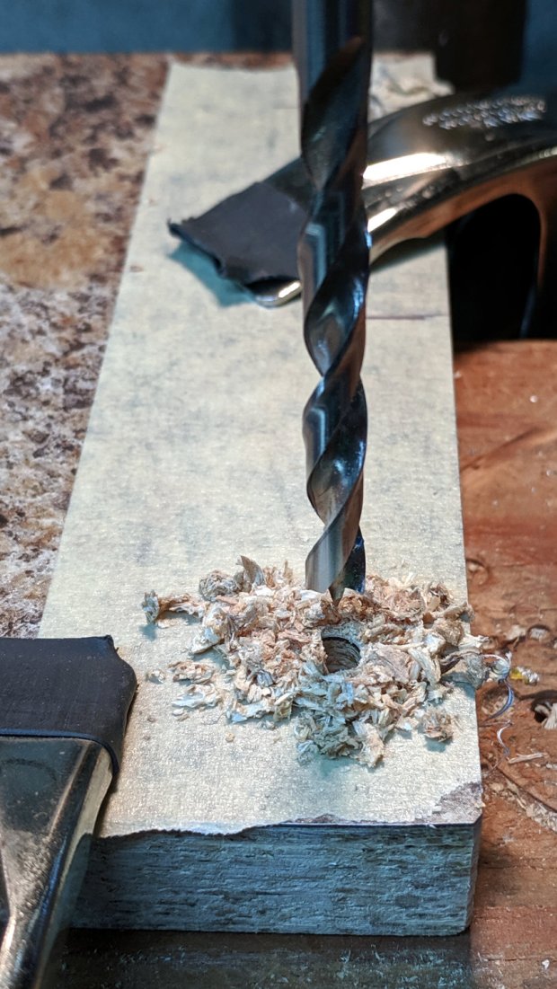
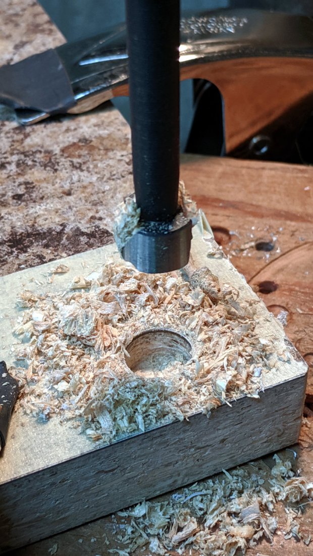
The countertop was thick enough to allow countersinking the screws slightly below the surface:
CNC 3018 Table Riser – screw countersink
I transfer-punched the screw clearance hole locations into the Celotex and drilled it with an ordinary twist drill. It wasn’t pretty, but nobody will ever notice.
Two sheets, maybe 1 mm thick, of closed-cell foam below the Celotext provide enough squish to align the top surface without straining anything. The screws are firmly tight, so they shouldn’t work their way loose under minimal engraving loads.
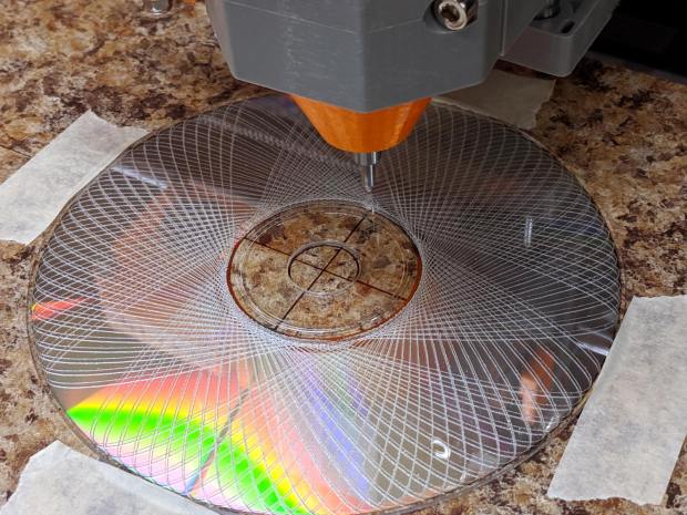
Taping the CDs to the surface works well for now, although a simpler version of the fixture may be in order.