The Smell of Molten Projects in the Morning

Ed Nisley's Blog: Shop notes, electronics, firmware, machinery, 3D printing, laser cuttery, and curiosities. Contents: 100% human thinking, 0% AI slop.

Tag: Improvements

Making the world a better place, one piece at a time

  • Tour Easy Rear Running Light: LED Lens Assembly

    Tour Easy Rear Running Light: LED Lens Assembly

    Having discovered the need for careful alignment of the LED PCB with the lens, I paid more attention to detail this time around.

    The LEDs arrive soldered to PCBs atop aluminum star heat spreaders, but the one I picked out of the bag looked slightly misaligned. Unsoldering it showed a smear of solder paste had melted across the central pad:

    1 W LED PCB - errant solder
    1 W LED PCB – errant solder

    The LED has a die contact slug on the bottom which, I suppose, could be directly soldered to the spreader. For my simple needs, removing the errant solder, plunking the LED atop a layer of heatsink compound, and resoldering the leads should suffice:

    1 W LED PCB - wire layout
    1 W LED PCB – wire layout

    The LED holder has a pair of slots aligning it with the LED leads on the PCB. The base of the holder sits flush against the PCB, so the wires must attach directly to the LED pads.

    I ran the wires for the amber light through holes close to the pads:

    1 W LED Running Light - heatsink fit
    1 W LED Running Light – heatsink fit

    Which required chewing two passages in the base of the holder:

    1 W LED Running Light - wiring
    1 W LED Running Light – wiring

    It turns out the 5° and 10° lenses are strongly conical and leave plenty of room around the LED to run a wire around the inside of the holder, so I drilled a pair of holes to put both wires on the same side of the circuit plate:

    Tour Easy Rear Running Light - circuit plate attachment
    Tour Easy Rear Running Light – circuit plate attachment

    The holder required minor surgery to let the wire double back on itself over the LED pad:

    1 W LED Holder - wire passage
    1 W LED Holder – wire passage

    The wires thread through two holes drilled in the plastic holder:

    Tour Easy Rear Running Light - clamped LED assembly
    Tour Easy Rear Running Light – clamped LED assembly

    More urethane adhesive glues the PCB to the LED holder, with the clamp applying pressure to the lens to ensure the lens seats properly around the LED. It turned out that worked well and the light has a nicely rounded beam.

    With the optics bonded together, metal-filled JB Weld epoxy attaches the heat spreader to the heatsink with good thermal conductivity:

    Tour Easy Rear Running Light - clamped LED heatsink
    Tour Easy Rear Running Light – clamped LED heatsink

    The LED holder is a slide fit in the heatsink, so the clamps can keep the PCB flat on the bottom of the recess while the epoxy gets a good grip on all parts.

    Now it’s just a matter of wiring everything up!

  • Rear Running Light: Tour Easy Seat Clamp

    Rear Running Light: Tour Easy Seat Clamp

    With the amber front running light blinking away, it’s time to replace the decade-old Planet Bike Superflash behind the seat:

    Superflash on Tour Easy
    Superflash on Tour Easy

    The new mount descends directly from the clamps holding the fairing strut on the handlebars and various hose clamps:

    Rear Running Light Seat Clamp - solid model
    Rear Running Light Seat Clamp – solid model

    The central block has two quartets of brass inserts epoxied inside:

    Rear Running Light Seat Clamp - sectioned - solid model
    Rear Running Light Seat Clamp – sectioned – solid model

    That means I can install the light, then mount the whole affair on the bike, without holding everything together while fiddling with overly long screws.

    A trial fit with the not-yet-cut-to-length 25.3 (-ish) PVC pipe body tube:

    Rear Running Light - Tour Easy seat clamp trial fit
    Rear Running Light – Tour Easy seat clamp trial fit

    The aluminum plates have the standard used-car finish: nice polish over deep scratches.

    Although I’ve been thinking of mounting the light below the seat rail, as shown, it can also sit above the rail.

    Mary hauls seedlings and suchlike to the garden in a plastic drawer bungied to the rack, with the SuperFlash serving as an anchor point; this light may need fine tuning for that purpose.

    The OpenSCAD source code as a GitHub Gist:

    // Rear running light clamp for Tour Easy seat strut
    // Ed Nisley – KE4ZNU – 2021-09
    Layout = "Show"; // [Show,Build,Block]
    Section = true;
    /* [Hidden] */
    ThreadThick = 0.25;
    ThreadWidth = 0.40;
    HoleWindage = 0.2;
    Protrusion = 0.1; // make holes end cleanly
    function IntegerMultiple(Size,Unit) = Unit * ceil(Size / Unit);
    ID = 0;
    OD = 1;
    LENGTH = 2;
    inch = 25.4;
    //———————-
    // Dimensions
    // Light case along X axis, seat strut along Y, Z=0 at strut centerline
    LightOD = 25.4 + HoleWindage;
    StrutOD = 5/8 * inch + HoleWindage;
    PlateThick = 1/16 * inch;
    WallThick = 2.0;
    Kerf = ThreadThick;
    Screw = [3.0,6.8,4.0]; // M3 OD=washer, length=nut + washers
    Insert = [3.0,5.4,8.0 + 1.0]; // splined brass insert
    RoundRadius = IntegerMultiple(Screw[OD]/2,0.5); // corner rounding
    ScrewOC = [IntegerMultiple(StrutOD + 2*WallThick + Screw[ID],1.0),
    IntegerMultiple(LightOD + 2*WallThick + Screw[ID],1.0)];
    echo(str("Screw OC: ",ScrewOC));
    BlockSize = [ScrewOC.x + Insert[OD] + 2*WallThick,
    ScrewOC.y + Insert[OD] + 2*WallThick,
    LightOD + StrutOD + 3*WallThick];
    echo(str("Block: ",BlockSize));
    BaseOffset = -(WallThick + LightOD/2); // block bottom to centerline
    StrutOffset = LightOD/2 + WallThick + StrutOD/2; // light centerline to strut centerline
    echo(str("Strut screw min: ",IntegerMultiple(PlateThick + WallThick + StrutOD/2 + Insert[LENGTH]/2,1.0)));
    echo(str("Light screw min: ",IntegerMultiple(PlateThick + WallThick + LightOD/2 + Insert[LENGTH]/2,1.0)));
    NumSides = 2*3*4;
    //———————-
    // Useful routines
    module PolyCyl(Dia,Height,ForceSides=0) { // based on nophead's polyholes
    Sides = (ForceSides != 0) ? ForceSides : (ceil(Dia) + 2);
    FixDia = Dia / cos(180/Sides);
    cylinder(r=(FixDia + HoleWindage)/2,
    h=Height,
    $fn=Sides);
    }
    // Block with light along X axis
    module Block() {
    difference() {
    hull()
    for (i=[-1,1], j=[-1,1])
    translate([i*(BlockSize.x/2 – RoundRadius),j*(BlockSize.y/2 – RoundRadius),BaseOffset])
    cylinder(r=RoundRadius,h=BlockSize.z,$fn=NumSides);
    for (i=[-1,1], j=[-1,1])
    translate([i*ScrewOC.x/2,j*ScrewOC.y/2,BaseOffset – Protrusion])
    rotate(180/8)
    PolyCyl(Screw[ID],BlockSize.z + 2*Protrusion,8);
    for (i=[-1,1], j=[-1,1])
    translate([i*ScrewOC.x/2,j*ScrewOC.y/2,0]) {
    translate([0,0,-Protrusion])
    rotate(180/8)
    PolyCyl(Insert[OD],Insert[LENGTH] + 1*Protrusion,8);
    translate([0,0,(StrutOffset – Insert[LENGTH] – Kerf/2 + Protrusion)])
    rotate(180/8)
    PolyCyl(Insert[OD],Insert[LENGTH] + 1*Protrusion,8);
    }
    translate([-BlockSize.x,0,0])
    rotate([0,90,0])
    cylinder(d=LightOD,h=2*BlockSize.x,$fn=NumSides);
    translate([0,BlockSize.y,StrutOffset])
    rotate([90,0,0])
    cylinder(d=StrutOD,h=2*BlockSize.y,$fn=NumSides);
    translate([0,0,StrutOffset])
    cube([2*BlockSize.x,2*BlockSize.y,Kerf],center=true);
    cube([2*BlockSize.x,2*BlockSize.y,Kerf],center=true);
    }
    }
    //- Build it
    if (Layout == "Block")
    if (Section)
    difference() {
    Block();
    rotate(atan(ScrewOC.y/ScrewOC.x))
    translate([0,BlockSize.y,0])
    cube(2*BlockSize,center=true);
    }
    else
    Block();
    if (Layout == "Show") {
    Block();
    color("Green",0.25)
    translate([-BlockSize.x,0,0])
    rotate([0,90,0])
    cylinder(d=LightOD,h=2*BlockSize.x,$fn=NumSides);
    color("Green",0.25)
    translate([0,BlockSize.y,StrutOffset])
    rotate([90,0,0])
    cylinder(d=StrutOD,h=2*BlockSize.y,$fn=NumSides);
    }
    if (Layout == "Build") {
    translate([-1.2*BlockSize.x,0,-BaseOffset])
    difference() {
    Block();
    translate([0,0,BlockSize.z])
    cube(2*BlockSize,center=true);
    }
    translate([1.2*BlockSize.x,0,StrutOD/2 + WallThick])
    difference() {
    rotate([180,0,0])
    translate([0,0,-StrutOffset])
    Block();
    translate([0,0,BlockSize.z])
    cube(2*BlockSize,center=true);
    }
    translate([0,0,StrutOffset – Kerf/2])
    rotate([180,0,0])
    intersection() {
    Block();
    translate([0,0,StrutOffset/2])
    cube([2*BlockSize.x,2*BlockSize.y,StrutOffset],center=true);
    }
    }

  • Micro-Mark Bandsaw: Acetal Blade Guide

    Micro-Mark Bandsaw: Acetal Blade Guide

    The Micro-Mark bandsaw has a metal blade guide below the table that contributes to the awful noise it makes while running, even when it’s not cutting anything. Having recently touched the Delrin = acetal rod stash, a simple project came to mind.

    A doodle with the original metal guide dimensions:

    Micro-Mark Bandsaw - metal blade guide dimensions
    Micro-Mark Bandsaw – metal blade guide dimensions

    The 10 mm dimension is non-critical, so I started with a 1/2 inch acetal rod and turned the stub end to match.

    A doodle suggested how to carve the slot with a 20.5 mil = 0.52 mm slitting saw, with the offset from a Z touchoff at the top:

    Micro-Mark Bandsaw - acetal blade guide - slitting doodles
    Micro-Mark Bandsaw – acetal blade guide – slitting doodles

    The V block setup required swapping out the overly long OEM screw for a shorter 5 mm SHCS to clear the Sherline’s motor:

    Micro-Mark Bandsaw - acetal guide slitting
    Micro-Mark Bandsaw – acetal guide slitting

    The end result looked pretty good:

    Micro-Mark Bandsaw - acetal vs steel blade guides
    Micro-Mark Bandsaw – acetal vs steel blade guides

    And it looks like it pretty much belongs in the saw:

    Micro-Mark Bandsaw - acetal blade guide installed
    Micro-Mark Bandsaw – acetal blade guide installed

    The 6 mm stud goes into a hole in the frame, where a setscrew holds it in place. You must remove the blade to extract / replace the guide, with the correct position having the end of the slot just touching the back of the blade.

    The foam ring apparently keeps crud away from the stud on the backside; I doubt it’s mission-critical.

    The saw became somewhat quieter; the ball bearing guides above the table now generate most of the racket. At some point I’ll try replacing them with a block, probably made from UHMW, with a simple slit to guide the blade.

    Plastic guides may not last as long as the steel ones, but occasional replacements will be worth it if the saw runs quieter.

  • Tenergy 18650 Lithium Cells: Four Years of Running Lights

    Tenergy 18650 Lithium Cells: Four Years of Running Lights

    With the amber daytime running light connected to the Bafang’s headlight output and the Anker flashlight on the other side of the fairing getting fewer power-on hours, it’s a good time to see how those four Tenergy lithium 18650 cells are doing:

    Tenergy 18650 Protected - 2021-09-09
    Tenergy 18650 Protected – 2021-09-09

    The overall capacity is down by 10%, with the voltage depressed by 120 mV over most of the curve.

    Although I don’t keep daily records, the back of the envelope reveals 150 to 200 hour-long rides per year during the last four years, so call it 700 charging cycles:

    Anker LC40 Flashlight - Anodizing fade
    Anker LC40 Flashlight – Anodizing fade

    High brightness draws 1.5 A and low is 50% duty cycle, so a typical ride requires 750 mA·h = 2.5 W·h. Each cell lives for three or four rides with the LED set to low brightness and the numbers work out close enough.

  • Depth Gauge Mounting Rods

    Depth Gauge Mounting Rods

    A depth gauge arrived with a 3/8 inch = 9.5 mm mounting rod that fit one of my magnetic bases, but another base in my collection has a 5/16 inch = 7.9 mm clamp. Having recently rummaged through the aluminum rod stash, this happened:

    Depth Gauge mounting rods
    Depth Gauge mounting rods

    The original rod at the top has an M6 thread, the drawer of random M6 screws provided suitable volunteers, and a bit of lathe work removed / shaped their heads accordingly.

    The shorter rod has a blind hole, with a dab of epoxy holding the headless screw in place. Not that it matters, but the lathe held them in alignment for curing:

    Depth Gauge mounting rod - epoxy alignment
    Depth Gauge mounting rod – epoxy alignment

    The longer rod got drilled all the way through, with more epoxy holding the screw, and, even with a relatively loose fit, no worries about alignment.

    The longer rod gets the clamp away from the depth gauge’s base plate for better positioning:

    Depth Gauge mounting rod - in use
    Depth Gauge mounting rod – in use

    They’ll surely come in handy along the way …

  • Tour Easy: Bafang BBS02 Lower Power

    Tour Easy: Bafang BBS02 Lower Power

    It turns out Mary rarely used assist level 6 and had no use for levels 7 and 8 of my derated BBS02 configuration:

    LC=15
    ALC0=0
    ALC1=5
    ALC2=7
    ALC3=16
    ALC4=25
    ALC5=37
    ALC6=51
    ALC7=67
    ALC8=85
    ALC9=100
    

    Level 9 must be 100% of the maximum motor current so the throttle can apply full power to get out of the way in a hurry.

    The new and even more derated configuration allows small-step assist level selection for our usual riding, at the cost of an unused huge step to level 9 for the throttle:

    [Basic]
    LBP=42
    LC=18
    ALC0=0
    ALC1=4
    ALC2=6
    ALC3=9
    ALC4=15
    ALC5=20
    ALC6=25
    ALC7=30
    ALC8=40
    ALC9=100
    ALBP0=0
    ALBP1=100
    ALBP2=100
    ALBP3=100
    ALBP4=100
    ALBP5=100
    ALBP6=100
    ALBP7=100
    ALBP8=100
    ALBP9=100
    WD=12
    SMM=0
    SMS=1
    [Pedal Assist]
    PT=3
    DA=0
    SL=0
    SSM=4
    WM=0
    SC=20
    SDN=4
    TS=15
    CD=8
    SD=5
    KC=100
    [Throttle Handle]
    SV=11
    EV=42
    MODE=1
    DA=10
    SL=0
    SC=5
    

    The LC=18 line limits the maximum motor current to 18 A, rather than the rated 24 A, which may improve controller MOSFET longevity; reliable evidence is hard to come by. Controller failures seem to happen more often to riders who value jackrabbit acceleration on harsh terrain, so it may make little difference for road cyclists.

    So level 5 now selects 75% × 20% = 15% of the motor’s nominal 750 W:

    Tour Easy Bafang - display 26 mi
    Tour Easy Bafang – display 26 mi

    Call it 115 W: we’re both getting plenty of exercise!

  • Tour Easy 1 W Amber Running Light: Holder and First Light

    Tour Easy 1 W Amber Running Light: Holder and First Light

    Wrapping a left-side ball mount around the PVC case produced a holder:

    Fairing 1 W LED Mount - Left side - show view
    Fairing 1 W LED Mount – Left side – show view

    Which looks like this in real life:

    1 W Amber Running Light - installed front
    1 W Amber Running Light – installed front

    The support structure under the arch required a bit more cleanup than it got, so the clamp didn’t quite close around the ball on the first full test:

    1 W Amber Running Light - installed side
    1 W Amber Running Light – installed side

    Both the phone camera and the eyeballometer report the 1 W amber LED isn’t quite as bright as the 400 lumen Anker flashlight on its low setting:

    1 W Amber Running Light - First Light
    1 W Amber Running Light – First Light

    Stir the unusual (for a bike) amber color together with some blinkiness, though, and it’s definitely attention-getting.

    The OpenSCAD source code as a GitHub Gist:

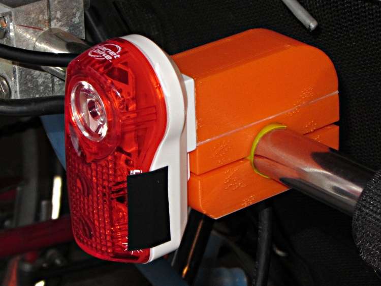
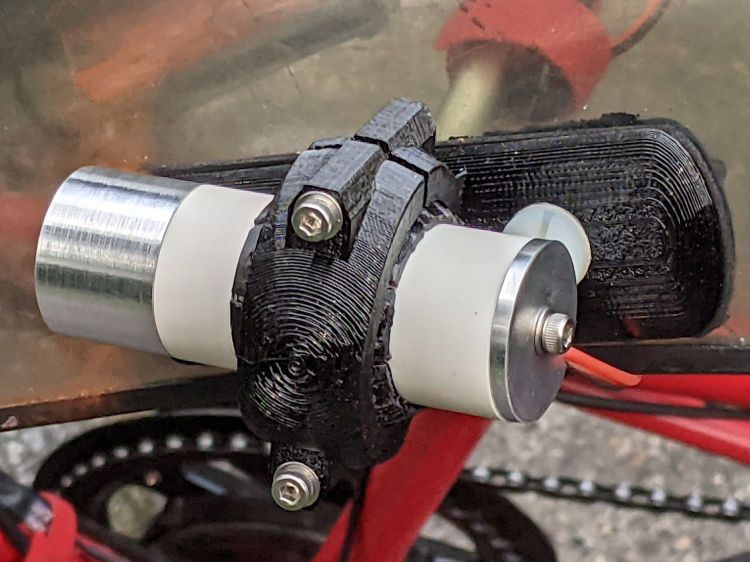
    // Tour Easy Fairing Flashlight Mount
    // Ed Nisley KE4ZNU – July 2017
    // August 2017 –
    // August 2020 – add reinforcing columns under mount cradle
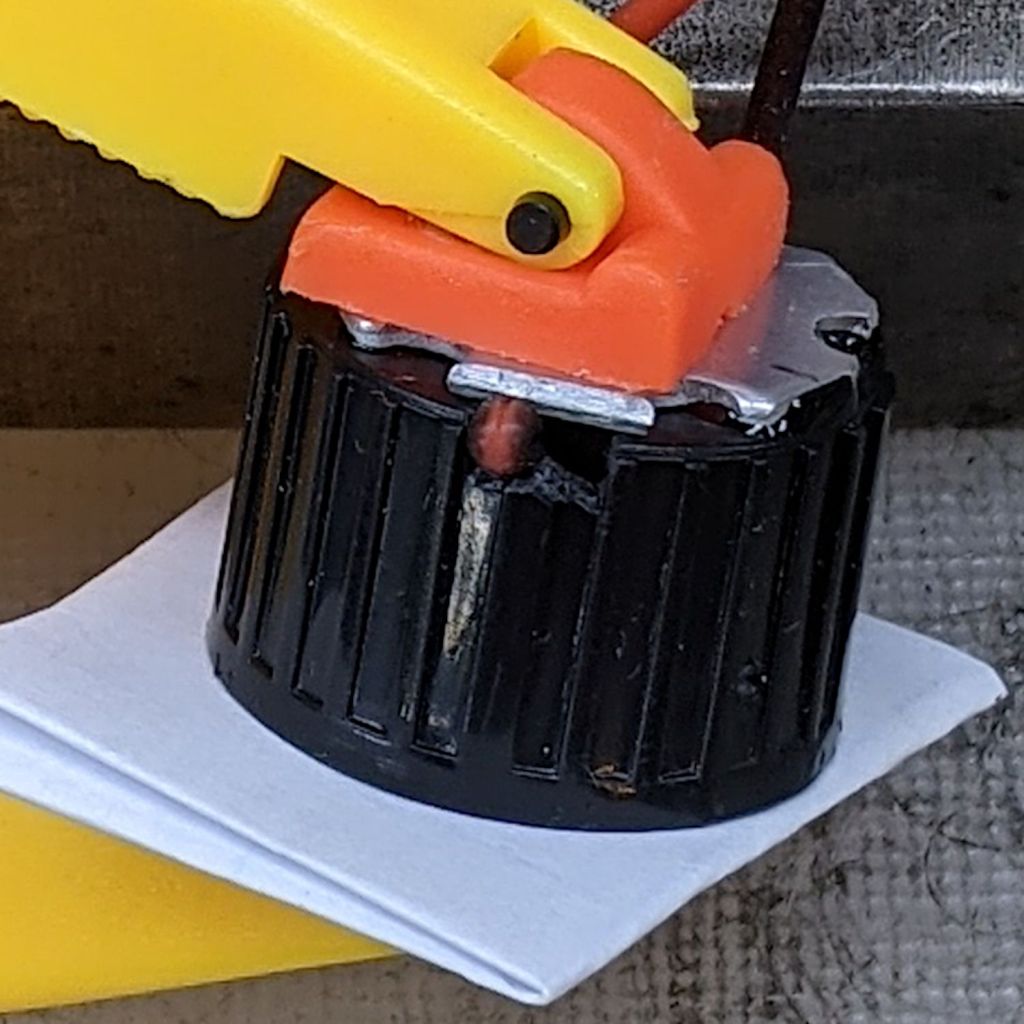
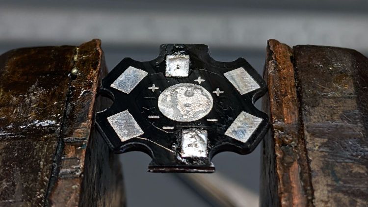
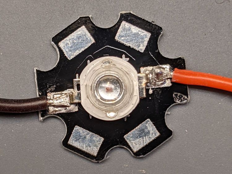
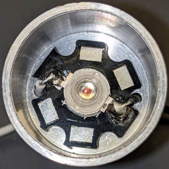
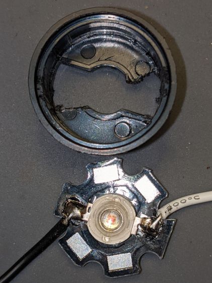
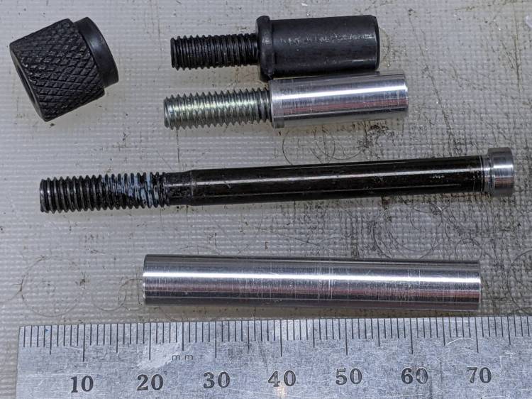
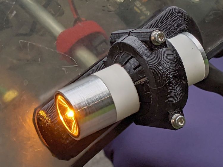
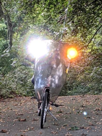
    // August 2021 – 1 W Amber LED
    /* [Build Options] */
    FlashName = "1WLED"; // [AnkerLC40,AnkerLC90,J5TactV2,InnovaX5,Sidemarker,Clearance,Laser,1WLED]
    Component = "BallClamp"; // [Ball, BallClamp, Mount, Plates, Bracket, Complete]
    Layout = "Build"; // [Build, Show]
    Support = true;
    MountSupport = true;
    /* [Hidden] */
    ThreadThick = 0.25; // [0.20, 0.25]
    ThreadWidth = 0.40; // [0.40]
    function IntegerMultiple(Size,Unit) = Unit * ceil(Size / Unit);
    Protrusion = 0.01; // [0.01, 0.1]
    HoleWindage = 0.2;
    /* [Fairing Mount] */
    Side = "Right"; // [Right,Left]
    ToeIn = -10; // inward from ahead
    Tilt = 20; // upward from forward (M=20 E=10)
    Roll = 0; // outward from top
    //- Screws and inserts
    /* [Hidden] */
    ID = 0;
    OD = 1;
    LENGTH = 2;
    /* [Hidden] */
    ClampInsert = [3.0,4.2,8.0];
    ClampScrew = [3.0,5.9,35.0]; // thread dia, head OD, screw length
    ClampScrewWasher = [3.0,6.75,0.5];
    ClampScrewNut = [3.0,6.1,4.0]; // nyloc nut
    /* [Hidden] */
    F_NAME = 0;
    F_GRIPOD = 1;
    F_GRIPLEN = 2;
    LightBodies = [
    ["AnkerLC90",26.6,48.0],
    ["AnkerLC40",26.6,55.0],
    ["J5TactV2",25.0,30.0],
    ["InnovaX5",22.0,55.0],
    ["Sidemarker",15.0,20.0],
    ["Clearance",50.0,20.0],
    ["Laser",10.0,30.0],
    ["1WLED",25.4,40.0],
    ];
    //- Fairing Bracket
    // Magic numbers taken from the actual fairing mount
    /* [Hidden] */
    inch = 25.4;
    BracketHoleOD = 0.25 * inch; // 1/4-20 bolt holes
    BracketHoleOC = 1.0 * inch; // fairing hole spacing
    // usually 1 inch, but 15/16 on one fairing
    Bracket = [48.0,16.3,3.6 – 0.6]; // fairing bracket end plate overall size
    BracketHoleOffset = (3/8) * inch; // end to hole center
    BracketM = 3.0; // endcap arc height
    BracketR = (pow(BracketM,2) + pow(Bracket[1],2)/4) / (2*BracketM); // … radius
    //- Base plate dimensions
    Plate = [100.0,30.0,6*ThreadThick + Bracket[2]];
    PlateRad = Plate[1]/4;
    RoundEnds = true;
    echo(str("Base plate thick: ",Plate[2]));
    //- Select flashlight data from table
    echo(str("Flashlight: ",FlashName));
    FlashIndex = search([FlashName],LightBodies,1,0)[F_NAME];
    //- Set ball dimensions
    BallWall = 5.0; // max ball wall thickness
    echo(str("Ball wall: ",BallWall));
    BallOD = IntegerMultiple(LightBodies[FlashIndex][F_GRIPOD] + 2*BallWall,1.0);
    echo(str(" OD: ",BallOD));
    BallLength = IntegerMultiple(min(sqrt(pow(BallOD,2) – pow(LightBodies[FlashIndex][F_GRIPOD],2)) – 2*4*ThreadThick,
    LightBodies[FlashIndex][F_GRIPLEN]),1.0);
    echo(str(" length: ",BallLength));
    BallSides = 8*4;
    //- Set clamp ring dimensions
    //ClampOD = 50;
    ClampOD = BallOD + 2*5;
    echo(str("Clamp OD: ",ClampOD));
    ClampLength = min(20.0,0.75*BallLength);
    echo(str(" length: ",ClampLength));
    ClampScrewOC = IntegerMultiple((ClampOD + BallOD)/2,1);
    echo(str(" screw OC: ",ClampScrewOC));
    TiltMirror = (Side == "Right") ? [0,0,0] : [0,1,0];
    //- Adjust hole diameter to make the size come out right
    module PolyCyl(Dia,Height,ForceSides=0) { // based on nophead's polyholes
    Sides = (ForceSides != 0) ? ForceSides : (ceil(Dia) + 2);
    FixDia = Dia / cos(180/Sides);
    cylinder(r=(FixDia + HoleWindage)/2,h=Height,$fn=Sides);
    }
    //- Fairing Bracket
    // This part of the fairing mount supports the whole flashlight mount
    // Centered on screw hole
    module Bracket() {
    linear_extrude(height=Bracket[2],convexity=2)
    difference() {
    translate([(Bracket[0]/2 – BracketHoleOffset),0,0])
    offset(delta=ThreadWidth)
    intersection() {
    square([Bracket[0],Bracket[1]],center=true);
    union() {
    for (i=[-1,0,1]) // middle circle fills gap
    translate([i*(Bracket[0]/2 – BracketR),0])
    circle(r=BracketR);
    }
    }
    circle(d=BracketHoleOD/cos(180/8),$fn=8); // dead center at the origin
    }
    }
    //- General plate shape
    // Centered in the middle of the plate
    module PlateBlank() {
    difference() {
    intersection() {
    translate([0,0,Plate[2]/2]) // select upper half of spheres
    cube(Plate,center=true);
    hull()
    if (RoundEnds)
    for (i=[-1,1])
    translate([i*(Plate[0]/2 – PlateRad),0,0])
    resize([Plate[1]/2,Plate[1],2*Plate[2]])
    sphere(r=PlateRad); // nice round ends!
    else
    for (i=[-1,1], j=[-1,1])
    translate([i*(Plate[0]/2 – PlateRad),j*(Plate[1]/2 – PlateRad),0])
    resize([2*PlateRad,2*PlateRad,2*Plate[2]])
    sphere(r=PlateRad); // nice round corners!
    }
    translate([BracketHoleOC,0,-Protrusion]) // punch screw holes
    PolyCyl(BracketHoleOD,2*Plate[2],8);
    translate([-BracketHoleOC,0,-Protrusion])
    PolyCyl(BracketHoleOD,2*Plate[2],8);
    }
    }
    //- Inner plate
    module InnerPlate() {
    difference() {
    PlateBlank();
    translate([-BracketHoleOC,0,Plate[2] – Bracket[2] + Protrusion]) // punch fairing bracket
    Bracket();
    }
    }
    //- Outer plate
    // With optional legend for orientation and parameters
    module OuterPlate(Legend = true) {
    TextRotate = (Side == "Left") ? 0 : 180;
    difference() {
    PlateBlank();
    if (Legend)
    mirror([0,1,0])
    translate([0,0,-Protrusion])
    linear_extrude(height=3*ThreadThick + Protrusion) {
    translate([BracketHoleOC + 15,0,0])
    text(text=">>>",size=5,spacing=1.20,font="Arial",halign="center",valign="center");
    translate([-BracketHoleOC,8,0]) rotate(TextRotate)
    text(text=str("Toe ",ToeIn),size=5,spacing=1.20,font="Arial",halign="center",valign="center");
    translate([-BracketHoleOC,-8,0]) rotate(TextRotate)
    text(text=str("Tilt ",Tilt),size=5,spacing=1.20,font="Arial",halign="center",valign="center");
    translate([BracketHoleOC,-8,0]) rotate(TextRotate)
    text(text=Side,size=5,spacing=1.20,font="Arial",halign="center",valign="center");
    translate([BracketHoleOC,8,0]) rotate(TextRotate)
    text(text=str("Roll ",Roll),size=5,spacing=1.20,font="Arial",halign="center",valign="center");
    translate([0,0,0])
    rotate(90)
    text(text="KE4ZNU",size=4,spacing=1.20,font="Arial",halign="center",valign="center");
    }
    }
    }
    //- Slotted ball around flashlight
    // Print with brim to ensure adhesion!
    module SlotBall() {
    NumSlots = 8*2; // must be even, half cut from each end
    SlotWidth = 2*ThreadWidth;
    SlotBaseThick = 10*ThreadThick; // enough to hold finger ends together
    RibLength = (BallOD – LightBodies[FlashIndex][F_GRIPOD])/2;
    translate([0,0,(Layout == "Build") ? BallLength/2 : 0])
    rotate([0,(Layout == "Show") ? 90 : 0,0])
    difference() {
    intersection() {
    sphere(d=BallOD,$fn=2*BallSides); // basic ball
    cube([2*BallOD,2*BallOD,BallLength],center=true); // trim to length
    }
    translate([0,0,-LightBodies[FlashIndex][F_GRIPOD]])
    rotate(180/BallSides)
    PolyCyl(LightBodies[FlashIndex][F_GRIPOD],2*BallOD,BallSides); // remove flashlight body
    for (i=[0:NumSlots/2 – 1]) { // cut slots
    a=i*(2*360/NumSlots);
    SlotCutterLength = LightBodies[FlashIndex][F_GRIPOD];
    rotate(a)
    translate([SlotCutterLength/2,0,SlotBaseThick])
    cube([SlotCutterLength,SlotWidth,BallLength],center=true);
    rotate(a + 360/NumSlots)
    translate([SlotCutterLength/2,0,-SlotBaseThick])
    cube([SlotCutterLength,SlotWidth,BallLength],center=true);
    }
    }
    color("Yellow")
    if (Support && (Layout == "Build")) {
    for (i=[0:NumSlots-1]) {
    a = i*360/NumSlots;
    rotate(a + 180/NumSlots)
    translate([(LightBodies[FlashIndex][F_GRIPOD] + RibLength)/2 + ThreadWidth,0,BallLength/(2*4)])
    cube([RibLength,2*ThreadWidth,BallLength/4],center=true);
    }
    }
    }
    //- Clamp around flashlight ball
    BossLength = ClampScrew[LENGTH] – 1*ClampScrewWasher[LENGTH];
    BossOD = ClampInsert[OD] + 2*(6*ThreadWidth);
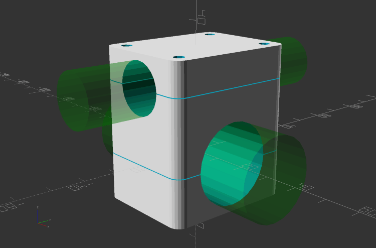
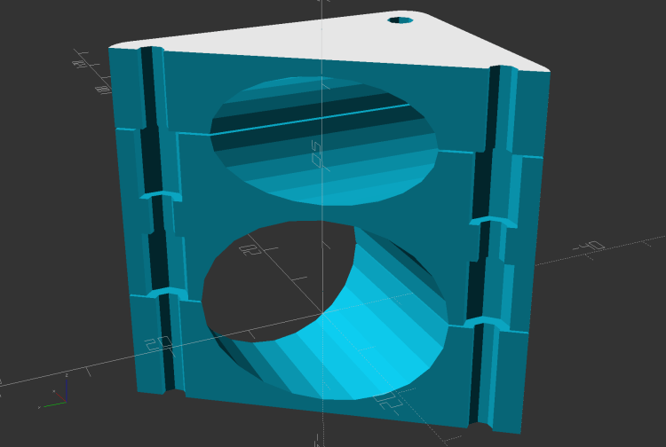
    module BallClamp(Section="All") {
    difference() {
    union() {
    intersection() {
    sphere(d=ClampOD,$fn=BallSides); // exterior ball clamp
    cube([ClampLength,2*ClampOD,2*ClampOD],center=true); // aiming allowance
    }
    hull()
    for (j=[-1,1])
    translate([0,j*ClampScrewOC/2,-BossLength/2])
    cylinder(d=BossOD,h=BossLength,$fn=6);
    }
    sphere(d=(BallOD + 1*ThreadThick),$fn=BallSides); // interior ball with minimal clearance
    for (j=[-1,1]) {
    translate([0,j*ClampScrewOC/2,-ClampOD]) // screw clearance
    PolyCyl(ClampScrew[ID],2*ClampOD,6);
    translate([0,j*ClampScrewOC/2, // insert clearance
    -0*(BossLength/2 – ClampInsert[LENGTH] – 3*ThreadThick) + Protrusion])
    rotate([0,180,0])
    PolyCyl(ClampInsert[OD],2*ClampOD,6);
    translate([0,j*ClampScrewOC/2, // insert transition
    -(BossLength/2 – ClampInsert[LENGTH] – 3*ThreadThick)])
    cylinder(d1=ClampInsert[OD]/cos(180/6),d2=ClampScrew[ID],h=6*ThreadThick,$fn=6);
    }
    if (Section == "Top")
    translate([0,0,-ClampOD/2])
    cube([2*ClampOD,2*ClampOD,ClampOD],center=true);
    else if (Section == "Bottom")
    translate([0,0,ClampOD/2])
    cube([2*ClampOD,2*ClampOD,ClampOD],center=true);
    }
    color("Yellow")
    if (Support) { // ad-hoc supports
    NumRibs = 6;
    RibLength = 0.5 * BallOD;
    RibWidth = 1.9*ThreadWidth;
    SupportOC = ClampLength / NumRibs;
    if (Section == "Top") // base plate for adhesion
    translate([0,0,ThreadThick])
    cube([ClampLength + 6*ThreadWidth,RibLength,2*ThreadThick],center=true);
    else if (Section == "Bottom")
    translate([0,0,-ThreadThick])
    cube([ClampLength + 6*ThreadWidth,RibLength,2*ThreadThick],center=true);
    render(convexity=2*NumRibs)
    intersection() {
    sphere(d=BallOD – 0*ThreadWidth); // cut at inner sphere OD
    cube([ClampLength + 2*ThreadWidth,RibLength,BallOD],center=true);
    if (Section == "Top") // select only desired section
    translate([0,0,ClampOD/2])
    cube([2*ClampOD,2*ClampOD,ClampOD],center=true);
    else if (Section == "Bottom")
    translate([0,0,-ClampOD/2])
    cube([2*ClampOD,2*ClampOD,ClampOD],center=true);
    union() { // ribs for E-Z build
    for (j=[-1,0,1])
    translate([0,j*SupportOC,0])
    cube([ClampLength,RibWidth,1.0*BallOD],center=true);
    for (i=[0:NumRibs]) // allow NumRibs + 1 to fill the far end
    translate([i*SupportOC – ClampLength/2,0,0])
    rotate([0,90,0])
    cylinder(d=BallOD – 2*ThreadThick,
    h=RibWidth,$fn=BallSides,center=true);
    }
    }
    }
    }
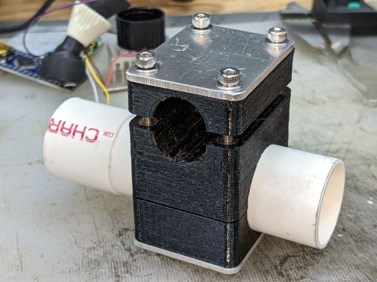
    //- Mount between fairing plate and flashlight ball
    // Build with support for bottom of clamp screws!
    module Mount() {
    MountShift = [ClampOD*sin(ToeIn/2),0,ClampOD/2];
    OuterPlate();
    mirror(TiltMirror) {
    intersection() {
    translate(MountShift)
    rotate([-Roll,ToeIn,Tilt])
    BallClamp("Bottom");
    translate([0,0,Plate.x/2 + 3*ThreadThick])
    cube(Plate.x,center=true);
    }
    if (MountSupport) // anchor outer corners at worst overhang
    color("Yellow") {
    RibWidth = 1.9*ThreadWidth;
    SupportOC = 0.1 * ClampLength;
    intersection() {
    difference() {
    rotate([0,0,Tilt])
    translate([(ClampOD – BallOD)*sin(ToeIn/2),0,3*ThreadThick]) // Z = avoid legends
    for (i=[-4.5,-2.5,0,2.0,4.5])
    translate([i*SupportOC – 0.0,0,(5 + Plate[2])/2])
    cube([RibWidth,0.7*ClampOD,(5 + Plate[2])],center=true);
    translate(MountShift)
    rotate([-Roll,ToeIn,Tilt])
    sphere(d=ClampOD – 2*ThreadWidth,$fn=BallSides);
    }
    translate([0,0,ClampOD/2])
    cube([Plate.x,Plate.y,ClampOD],center=true);
    }
    }
    }
    }
    //- Build things
    if (Component == "Bracket")
    Bracket();
    if (Component == "Ball")
    SlotBall();
    if (Component == "BallClamp")
    if (Layout == "Show")
    BallClamp("All");
    else if (Layout == "Build")
    BallClamp("Top");
    if (Component == "Mount")
    Mount();
    if (Component == "Plates") {
    translate([0,0.7*Plate[1],0])
    InnerPlate();
    translate([0,-0.7*Plate[1],0])
    OuterPlate(Legend = false);
    }
    if (Component == "Complete") {
    OuterPlate();
    mirror(TiltMirror) {
    translate([0,0,ClampOD/2 + BossOD*abs(sin(ToeIn))]) {
    rotate([-Roll,ToeIn,Tilt])
    SlotBall();
    rotate([-Roll,ToeIn,Tilt])
    BallClamp();
    }
    }
    }