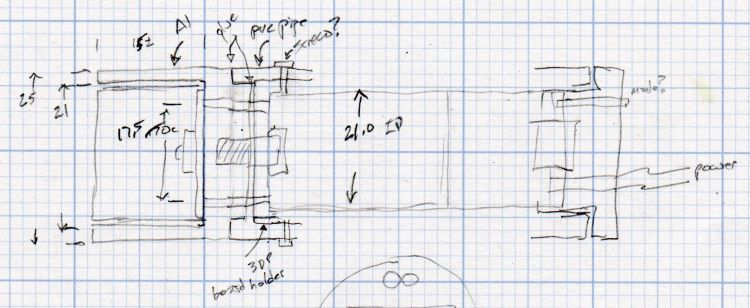
Wrapping a left-side ball mount around the PVC case produced a holder:

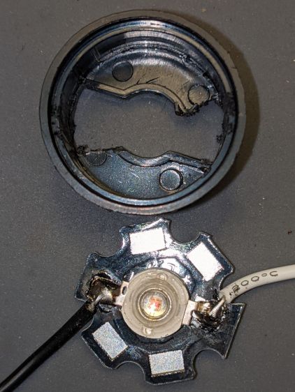
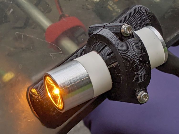
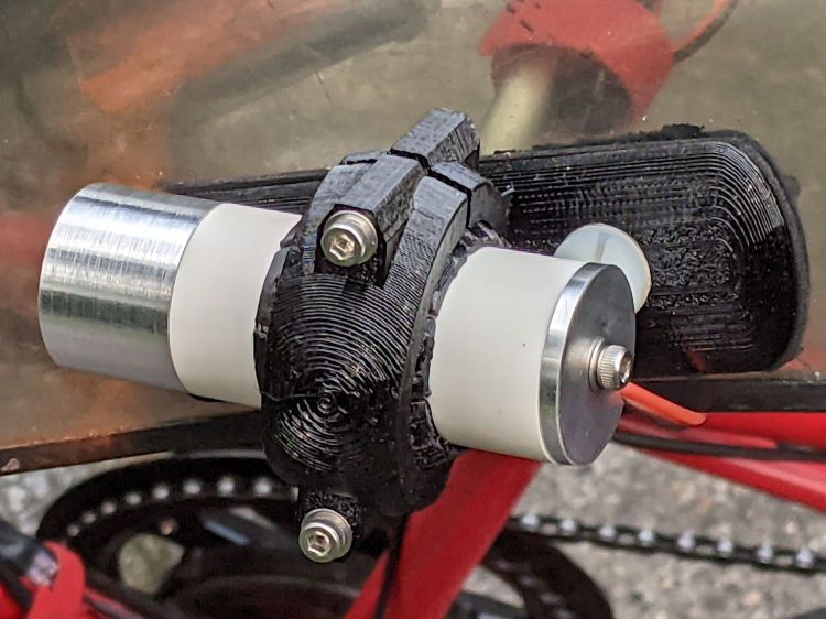
Which looks like this in real life:
The support structure under the arch required a bit more cleanup than it got, so the clamp didn’t quite close around the ball on the first full test:
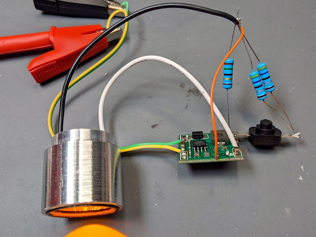
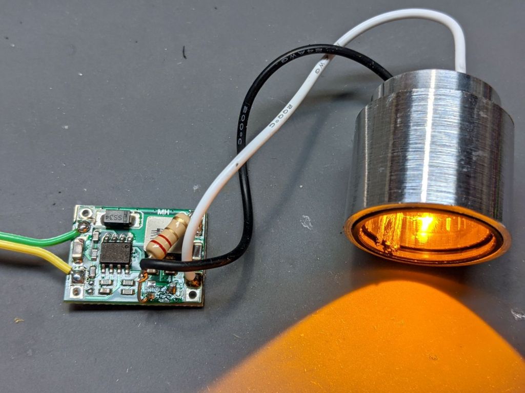
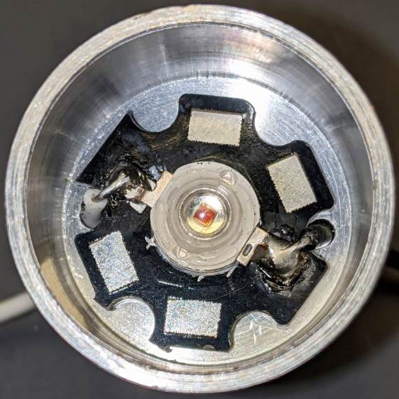
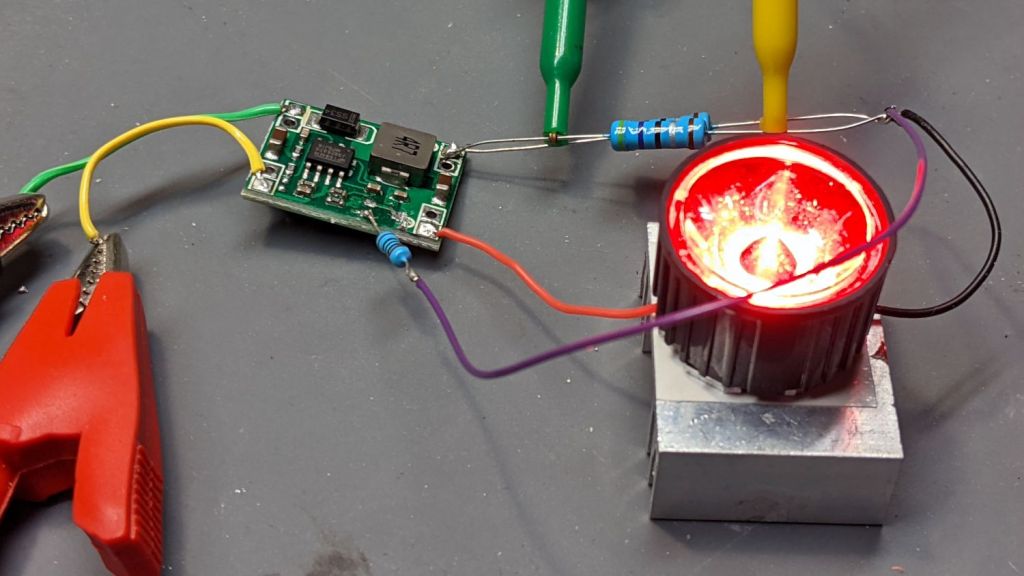
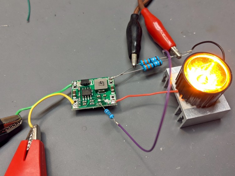
Both the phone camera and the eyeballometer report the 1 W amber LED isn’t quite as bright as the 400 lumen Anker flashlight on its low setting:
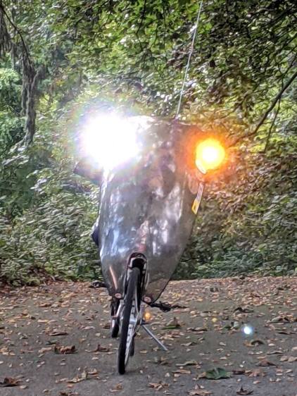
Stir the unusual (for a bike) amber color together with some blinkiness, though, and it’s definitely attention-getting.
The OpenSCAD source code as a GitHub Gist:
This file contains hidden or bidirectional Unicode text that may be interpreted or compiled differently than what appears below. To review, open the file in an editor that reveals hidden Unicode characters.
Learn more about bidirectional Unicode characters
| // Tour Easy Fairing Flashlight Mount | |
| // Ed Nisley KE4ZNU – July 2017 | |
| // August 2017 – | |
| // August 2020 – add reinforcing columns under mount cradle | |
| // August 2021 – 1 W Amber LED | |
| /* [Build Options] */ | |
| FlashName = "1WLED"; // [AnkerLC40,AnkerLC90,J5TactV2,InnovaX5,Sidemarker,Clearance,Laser,1WLED] | |
| Component = "BallClamp"; // [Ball, BallClamp, Mount, Plates, Bracket, Complete] | |
| Layout = "Build"; // [Build, Show] | |
| Support = true; | |
| MountSupport = true; | |
| /* [Hidden] */ | |
| ThreadThick = 0.25; // [0.20, 0.25] | |
| ThreadWidth = 0.40; // [0.40] | |
| function IntegerMultiple(Size,Unit) = Unit * ceil(Size / Unit); | |
| Protrusion = 0.01; // [0.01, 0.1] | |
| HoleWindage = 0.2; | |
| /* [Fairing Mount] */ | |
| Side = "Right"; // [Right,Left] | |
| ToeIn = -10; // inward from ahead | |
| Tilt = 20; // upward from forward (M=20 E=10) | |
| Roll = 0; // outward from top | |
| //- Screws and inserts | |
| /* [Hidden] */ | |
| ID = 0; | |
| OD = 1; | |
| LENGTH = 2; | |
| /* [Hidden] */ | |
| ClampInsert = [3.0,4.2,8.0]; | |
| ClampScrew = [3.0,5.9,35.0]; // thread dia, head OD, screw length | |
| ClampScrewWasher = [3.0,6.75,0.5]; | |
| ClampScrewNut = [3.0,6.1,4.0]; // nyloc nut | |
| /* [Hidden] */ | |
| F_NAME = 0; | |
| F_GRIPOD = 1; | |
| F_GRIPLEN = 2; | |
| LightBodies = [ | |
| ["AnkerLC90",26.6,48.0], | |
| ["AnkerLC40",26.6,55.0], | |
| ["J5TactV2",25.0,30.0], | |
| ["InnovaX5",22.0,55.0], | |
| ["Sidemarker",15.0,20.0], | |
| ["Clearance",50.0,20.0], | |
| ["Laser",10.0,30.0], | |
| ["1WLED",25.4,40.0], | |
| ]; | |
| //- Fairing Bracket | |
| // Magic numbers taken from the actual fairing mount | |
| /* [Hidden] */ | |
| inch = 25.4; | |
| BracketHoleOD = 0.25 * inch; // 1/4-20 bolt holes | |
| BracketHoleOC = 1.0 * inch; // fairing hole spacing | |
| // usually 1 inch, but 15/16 on one fairing | |
| Bracket = [48.0,16.3,3.6 – 0.6]; // fairing bracket end plate overall size | |
| BracketHoleOffset = (3/8) * inch; // end to hole center | |
| BracketM = 3.0; // endcap arc height | |
| BracketR = (pow(BracketM,2) + pow(Bracket[1],2)/4) / (2*BracketM); // … radius | |
| //- Base plate dimensions | |
| Plate = [100.0,30.0,6*ThreadThick + Bracket[2]]; | |
| PlateRad = Plate[1]/4; | |
| RoundEnds = true; | |
| echo(str("Base plate thick: ",Plate[2])); | |
| //- Select flashlight data from table | |
| echo(str("Flashlight: ",FlashName)); | |
| FlashIndex = search([FlashName],LightBodies,1,0)[F_NAME]; | |
| //- Set ball dimensions | |
| BallWall = 5.0; // max ball wall thickness | |
| echo(str("Ball wall: ",BallWall)); | |
| BallOD = IntegerMultiple(LightBodies[FlashIndex][F_GRIPOD] + 2*BallWall,1.0); | |
| echo(str(" OD: ",BallOD)); | |
| BallLength = IntegerMultiple(min(sqrt(pow(BallOD,2) – pow(LightBodies[FlashIndex][F_GRIPOD],2)) – 2*4*ThreadThick, | |
| LightBodies[FlashIndex][F_GRIPLEN]),1.0); | |
| echo(str(" length: ",BallLength)); | |
| BallSides = 8*4; | |
| //- Set clamp ring dimensions | |
| //ClampOD = 50; | |
| ClampOD = BallOD + 2*5; | |
| echo(str("Clamp OD: ",ClampOD)); | |
| ClampLength = min(20.0,0.75*BallLength); | |
| echo(str(" length: ",ClampLength)); | |
| ClampScrewOC = IntegerMultiple((ClampOD + BallOD)/2,1); | |
| echo(str(" screw OC: ",ClampScrewOC)); | |
| TiltMirror = (Side == "Right") ? [0,0,0] : [0,1,0]; | |
| //- Adjust hole diameter to make the size come out right | |
| module PolyCyl(Dia,Height,ForceSides=0) { // based on nophead's polyholes | |
| Sides = (ForceSides != 0) ? ForceSides : (ceil(Dia) + 2); | |
| FixDia = Dia / cos(180/Sides); | |
| cylinder(r=(FixDia + HoleWindage)/2,h=Height,$fn=Sides); | |
| } | |
| //- Fairing Bracket | |
| // This part of the fairing mount supports the whole flashlight mount | |
| // Centered on screw hole | |
| module Bracket() { | |
| linear_extrude(height=Bracket[2],convexity=2) | |
| difference() { | |
| translate([(Bracket[0]/2 – BracketHoleOffset),0,0]) | |
| offset(delta=ThreadWidth) | |
| intersection() { | |
| square([Bracket[0],Bracket[1]],center=true); | |
| union() { | |
| for (i=[-1,0,1]) // middle circle fills gap | |
| translate([i*(Bracket[0]/2 – BracketR),0]) | |
| circle(r=BracketR); | |
| } | |
| } | |
| circle(d=BracketHoleOD/cos(180/8),$fn=8); // dead center at the origin | |
| } | |
| } | |
| //- General plate shape | |
| // Centered in the middle of the plate | |
| module PlateBlank() { | |
| difference() { | |
| intersection() { | |
| translate([0,0,Plate[2]/2]) // select upper half of spheres | |
| cube(Plate,center=true); | |
| hull() | |
| if (RoundEnds) | |
| for (i=[-1,1]) | |
| translate([i*(Plate[0]/2 – PlateRad),0,0]) | |
| resize([Plate[1]/2,Plate[1],2*Plate[2]]) | |
| sphere(r=PlateRad); // nice round ends! | |
| else | |
| for (i=[-1,1], j=[-1,1]) | |
| translate([i*(Plate[0]/2 – PlateRad),j*(Plate[1]/2 – PlateRad),0]) | |
| resize([2*PlateRad,2*PlateRad,2*Plate[2]]) | |
| sphere(r=PlateRad); // nice round corners! | |
| } | |
| translate([BracketHoleOC,0,-Protrusion]) // punch screw holes | |
| PolyCyl(BracketHoleOD,2*Plate[2],8); | |
| translate([-BracketHoleOC,0,-Protrusion]) | |
| PolyCyl(BracketHoleOD,2*Plate[2],8); | |
| } | |
| } | |
| //- Inner plate | |
| module InnerPlate() { | |
| difference() { | |
| PlateBlank(); | |
| translate([-BracketHoleOC,0,Plate[2] – Bracket[2] + Protrusion]) // punch fairing bracket | |
| Bracket(); | |
| } | |
| } | |
| //- Outer plate | |
| // With optional legend for orientation and parameters | |
| module OuterPlate(Legend = true) { | |
| TextRotate = (Side == "Left") ? 0 : 180; | |
| difference() { | |
| PlateBlank(); | |
| if (Legend) | |
| mirror([0,1,0]) | |
| translate([0,0,-Protrusion]) | |
| linear_extrude(height=3*ThreadThick + Protrusion) { | |
| translate([BracketHoleOC + 15,0,0]) | |
| text(text=">>>",size=5,spacing=1.20,font="Arial",halign="center",valign="center"); | |
| translate([-BracketHoleOC,8,0]) rotate(TextRotate) | |
| text(text=str("Toe ",ToeIn),size=5,spacing=1.20,font="Arial",halign="center",valign="center"); | |
| translate([-BracketHoleOC,-8,0]) rotate(TextRotate) | |
| text(text=str("Tilt ",Tilt),size=5,spacing=1.20,font="Arial",halign="center",valign="center"); | |
| translate([BracketHoleOC,-8,0]) rotate(TextRotate) | |
| text(text=Side,size=5,spacing=1.20,font="Arial",halign="center",valign="center"); | |
| translate([BracketHoleOC,8,0]) rotate(TextRotate) | |
| text(text=str("Roll ",Roll),size=5,spacing=1.20,font="Arial",halign="center",valign="center"); | |
| translate([0,0,0]) | |
| rotate(90) | |
| text(text="KE4ZNU",size=4,spacing=1.20,font="Arial",halign="center",valign="center"); | |
| } | |
| } | |
| } | |
| //- Slotted ball around flashlight | |
| // Print with brim to ensure adhesion! | |
| module SlotBall() { | |
| NumSlots = 8*2; // must be even, half cut from each end | |
| SlotWidth = 2*ThreadWidth; | |
| SlotBaseThick = 10*ThreadThick; // enough to hold finger ends together | |
| RibLength = (BallOD – LightBodies[FlashIndex][F_GRIPOD])/2; | |
| translate([0,0,(Layout == "Build") ? BallLength/2 : 0]) | |
| rotate([0,(Layout == "Show") ? 90 : 0,0]) | |
| difference() { | |
| intersection() { | |
| sphere(d=BallOD,$fn=2*BallSides); // basic ball | |
| cube([2*BallOD,2*BallOD,BallLength],center=true); // trim to length | |
| } | |
| translate([0,0,-LightBodies[FlashIndex][F_GRIPOD]]) | |
| rotate(180/BallSides) | |
| PolyCyl(LightBodies[FlashIndex][F_GRIPOD],2*BallOD,BallSides); // remove flashlight body | |
| for (i=[0:NumSlots/2 – 1]) { // cut slots | |
| a=i*(2*360/NumSlots); | |
| SlotCutterLength = LightBodies[FlashIndex][F_GRIPOD]; | |
| rotate(a) | |
| translate([SlotCutterLength/2,0,SlotBaseThick]) | |
| cube([SlotCutterLength,SlotWidth,BallLength],center=true); | |
| rotate(a + 360/NumSlots) | |
| translate([SlotCutterLength/2,0,-SlotBaseThick]) | |
| cube([SlotCutterLength,SlotWidth,BallLength],center=true); | |
| } | |
| } | |
| color("Yellow") | |
| if (Support && (Layout == "Build")) { | |
| for (i=[0:NumSlots-1]) { | |
| a = i*360/NumSlots; | |
| rotate(a + 180/NumSlots) | |
| translate([(LightBodies[FlashIndex][F_GRIPOD] + RibLength)/2 + ThreadWidth,0,BallLength/(2*4)]) | |
| cube([RibLength,2*ThreadWidth,BallLength/4],center=true); | |
| } | |
| } | |
| } | |
| //- Clamp around flashlight ball | |
| BossLength = ClampScrew[LENGTH] – 1*ClampScrewWasher[LENGTH]; | |
| BossOD = ClampInsert[OD] + 2*(6*ThreadWidth); | |
| module BallClamp(Section="All") { | |
| difference() { | |
| union() { | |
| intersection() { | |
| sphere(d=ClampOD,$fn=BallSides); // exterior ball clamp | |
| cube([ClampLength,2*ClampOD,2*ClampOD],center=true); // aiming allowance | |
| } | |
| hull() | |
| for (j=[-1,1]) | |
| translate([0,j*ClampScrewOC/2,-BossLength/2]) | |
| cylinder(d=BossOD,h=BossLength,$fn=6); | |
| } | |
| sphere(d=(BallOD + 1*ThreadThick),$fn=BallSides); // interior ball with minimal clearance | |
| for (j=[-1,1]) { | |
| translate([0,j*ClampScrewOC/2,-ClampOD]) // screw clearance | |
| PolyCyl(ClampScrew[ID],2*ClampOD,6); | |
| translate([0,j*ClampScrewOC/2, // insert clearance | |
| -0*(BossLength/2 – ClampInsert[LENGTH] – 3*ThreadThick) + Protrusion]) | |
| rotate([0,180,0]) | |
| PolyCyl(ClampInsert[OD],2*ClampOD,6); | |
| translate([0,j*ClampScrewOC/2, // insert transition | |
| -(BossLength/2 – ClampInsert[LENGTH] – 3*ThreadThick)]) | |
| cylinder(d1=ClampInsert[OD]/cos(180/6),d2=ClampScrew[ID],h=6*ThreadThick,$fn=6); | |
| } | |
| if (Section == "Top") | |
| translate([0,0,-ClampOD/2]) | |
| cube([2*ClampOD,2*ClampOD,ClampOD],center=true); | |
| else if (Section == "Bottom") | |
| translate([0,0,ClampOD/2]) | |
| cube([2*ClampOD,2*ClampOD,ClampOD],center=true); | |
| } | |
| color("Yellow") | |
| if (Support) { // ad-hoc supports | |
| NumRibs = 6; | |
| RibLength = 0.5 * BallOD; | |
| RibWidth = 1.9*ThreadWidth; | |
| SupportOC = ClampLength / NumRibs; | |
| if (Section == "Top") // base plate for adhesion | |
| translate([0,0,ThreadThick]) | |
| cube([ClampLength + 6*ThreadWidth,RibLength,2*ThreadThick],center=true); | |
| else if (Section == "Bottom") | |
| translate([0,0,-ThreadThick]) | |
| cube([ClampLength + 6*ThreadWidth,RibLength,2*ThreadThick],center=true); | |
| render(convexity=2*NumRibs) | |
| intersection() { | |
| sphere(d=BallOD – 0*ThreadWidth); // cut at inner sphere OD | |
| cube([ClampLength + 2*ThreadWidth,RibLength,BallOD],center=true); | |
| if (Section == "Top") // select only desired section | |
| translate([0,0,ClampOD/2]) | |
| cube([2*ClampOD,2*ClampOD,ClampOD],center=true); | |
| else if (Section == "Bottom") | |
| translate([0,0,-ClampOD/2]) | |
| cube([2*ClampOD,2*ClampOD,ClampOD],center=true); | |
| union() { // ribs for E-Z build | |
| for (j=[-1,0,1]) | |
| translate([0,j*SupportOC,0]) | |
| cube([ClampLength,RibWidth,1.0*BallOD],center=true); | |
| for (i=[0:NumRibs]) // allow NumRibs + 1 to fill the far end | |
| translate([i*SupportOC – ClampLength/2,0,0]) | |
| rotate([0,90,0]) | |
| cylinder(d=BallOD – 2*ThreadThick, | |
| h=RibWidth,$fn=BallSides,center=true); | |
| } | |
| } | |
| } | |
| } | |
| //- Mount between fairing plate and flashlight ball | |
| // Build with support for bottom of clamp screws! | |
| module Mount() { | |
| MountShift = [ClampOD*sin(ToeIn/2),0,ClampOD/2]; | |
| OuterPlate(); | |
| mirror(TiltMirror) { | |
| intersection() { | |
| translate(MountShift) | |
| rotate([-Roll,ToeIn,Tilt]) | |
| BallClamp("Bottom"); | |
| translate([0,0,Plate.x/2 + 3*ThreadThick]) | |
| cube(Plate.x,center=true); | |
| } | |
| if (MountSupport) // anchor outer corners at worst overhang | |
| color("Yellow") { | |
| RibWidth = 1.9*ThreadWidth; | |
| SupportOC = 0.1 * ClampLength; | |
| intersection() { | |
| difference() { | |
| rotate([0,0,Tilt]) | |
| translate([(ClampOD – BallOD)*sin(ToeIn/2),0,3*ThreadThick]) // Z = avoid legends | |
| for (i=[-4.5,-2.5,0,2.0,4.5]) | |
| translate([i*SupportOC – 0.0,0,(5 + Plate[2])/2]) | |
| cube([RibWidth,0.7*ClampOD,(5 + Plate[2])],center=true); | |
| translate(MountShift) | |
| rotate([-Roll,ToeIn,Tilt]) | |
| sphere(d=ClampOD – 2*ThreadWidth,$fn=BallSides); | |
| } | |
| translate([0,0,ClampOD/2]) | |
| cube([Plate.x,Plate.y,ClampOD],center=true); | |
| } | |
| } | |
| } | |
| } | |
| //- Build things | |
| if (Component == "Bracket") | |
| Bracket(); | |
| if (Component == "Ball") | |
| SlotBall(); | |
| if (Component == "BallClamp") | |
| if (Layout == "Show") | |
| BallClamp("All"); | |
| else if (Layout == "Build") | |
| BallClamp("Top"); | |
| if (Component == "Mount") | |
| Mount(); | |
| if (Component == "Plates") { | |
| translate([0,0.7*Plate[1],0]) | |
| InnerPlate(); | |
| translate([0,-0.7*Plate[1],0]) | |
| OuterPlate(Legend = false); | |
| } | |
| if (Component == "Complete") { | |
| OuterPlate(); | |
| mirror(TiltMirror) { | |
| translate([0,0,ClampOD/2 + BossOD*abs(sin(ToeIn))]) { | |
| rotate([-Roll,ToeIn,Tilt]) | |
| SlotBall(); | |
| rotate([-Roll,ToeIn,Tilt]) | |
| BallClamp(); | |
| } | |
| } | |
| } |