Ed Nisley's Blog: Shop notes, electronics, firmware, machinery, 3D printing, laser cuttery, and curiosities. Contents: 100% human thinking, 0% AI slop.
Tag: Improvements
Making the world a better place, one piece at a time
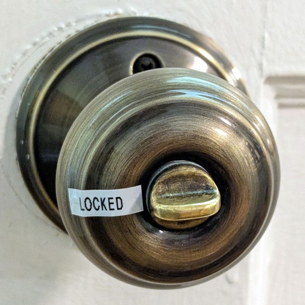
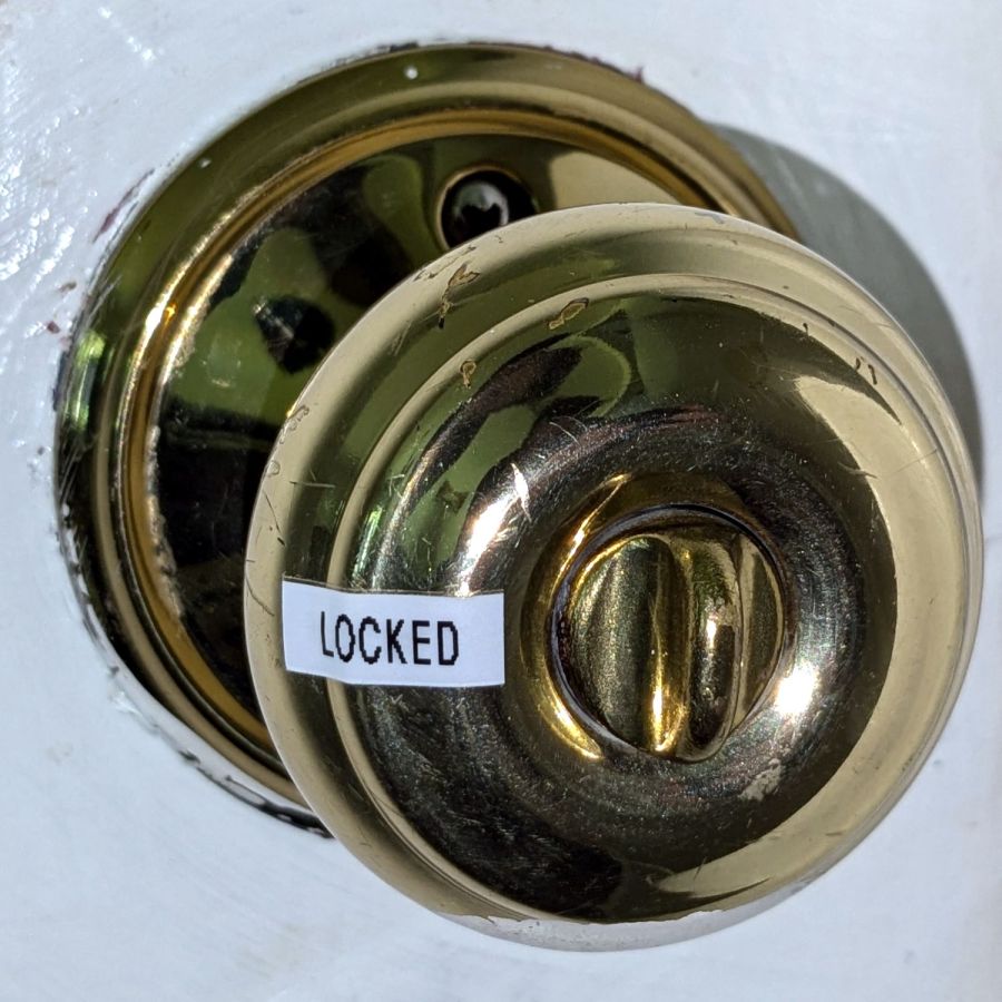
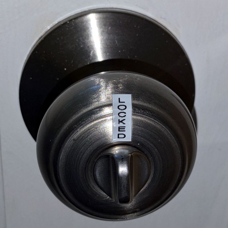
For the usual historic reasons, the exterior doors on our house all have different knobs with different lock orientations (and keys), so it’s difficult (for me, anyway) to verify they’re locked with just a glance. The correct solution of replacing all the knobs seems like a great deal of effort & expense for very little benefit.
This is easier, albeit considerably less stylish:
Doorknob 1
When the twisty thing aligns with the label, it’s locked:
Doorknob 3
No matter what orientation it has:
Doorknob 2
The scars in the paint show some of those doors have sported many knobs over the last half century or so.
You’d think such a thing could be standardized, but nope.
If we lived in a fancier house, I probably couldn’t get away with it.
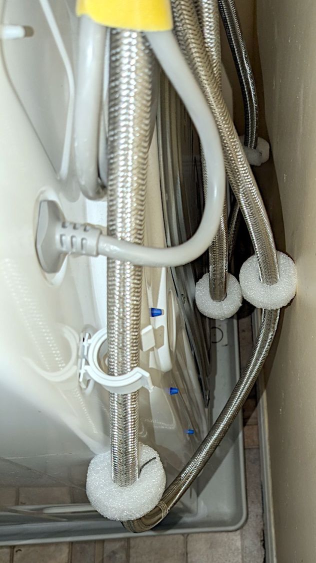
For obvious reasons, the water hoses tend to thump against the wall and the sheet-metal back of the clothes washer, so I added foam disks to mute the noise:
Clothes washer hose bumpers
They’re closed-cell polyethylene foam, laser-cut from a sheet about 15 mm thick. The cut is a yawning 2 mm wide near the top, but it pretty much doesn’t matter in this application.
The black line in the split is a snippet of the usual outdoor-rated foam tape, which probably won’t stick well to PE foam. If these fall apart, a cable tie around their waist should suffice.
The nice clip in the foreground is one of two intended to corral the drain hose. It’d be nice if LG included a few clips for the water hoses, but no matter where they were, the hoses would want to go elsewhere.
Although the house has a shower stall, I want to fix the cracks in its floor before we use it, so we’ve been taking showers in one of the bathtubs. As is always the case, the soap tray / grab handle is positioned for someone reclining in the tub, making it both too low and too awkward for either of us.
Normally, I’d just stick a soap tray on the wall and be done with it, but the tub wall is covered with small tiles that defeat sticky cups; more permanent adhesives are not under discussion.
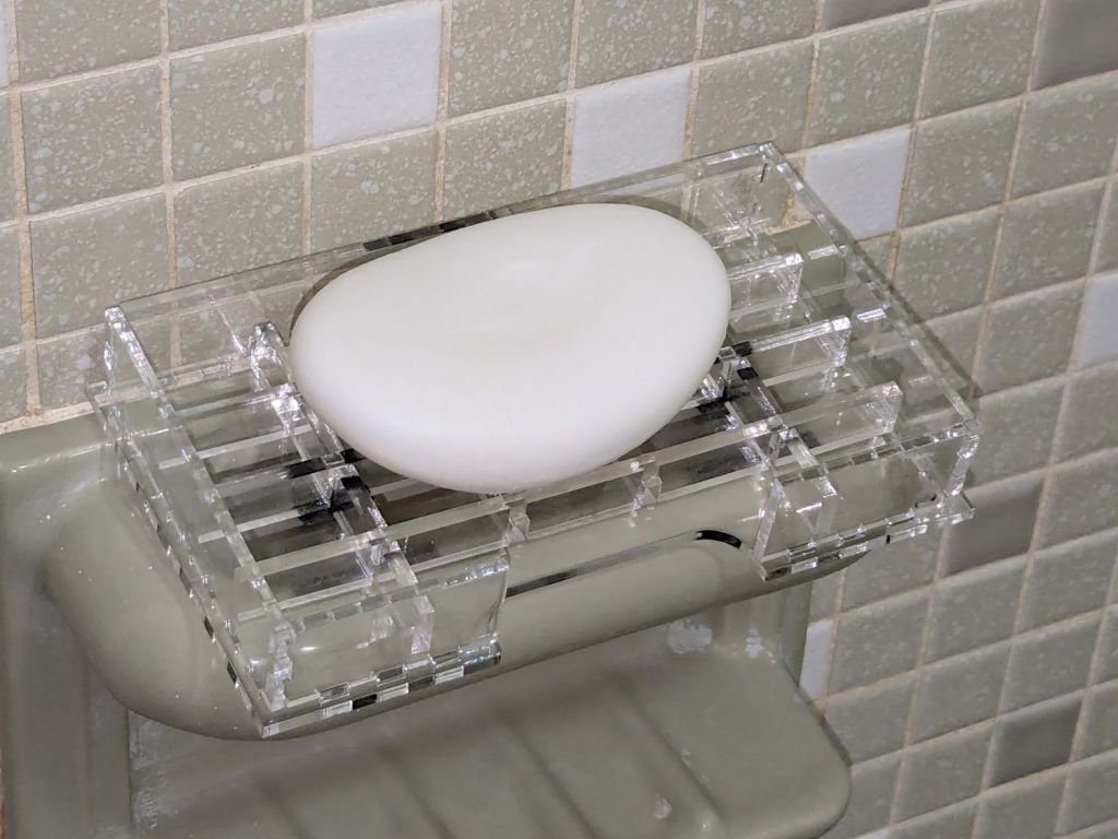
So I dropped a TrayInsert grid into a NotesHolder box, stuck them to the existing fixture with snippets of (regrettably black) outdoor-rated foam tape, and there it is:
Acrylic grid bathtub soap tray
You’ll surely not have 3.2 mm acrylic for the grid and 2.5 mm acrylic for the box, but those two linkies have the jawbreaker URLs required to regenerate exactly what I built using the incomparable boxes.py site and you can tweak them as needed.
The general concept had it stick out a bit from the fixture handle to let soap gunk drip into the tub, not down the wall, and to have an easily removable grid for cleaning. I doodled all manner of clever hooks to engage the ceramic handle before coming to my senses; this is a prototype, it may not solve the problem very well at all, so let’s find out if it works before making it better.
The WordPress AI urges me to remind you of the safety issues surrounding DIY projects. IMO, should you need such reminders, they won’t do you any good and you must immediately stop reading this blog.
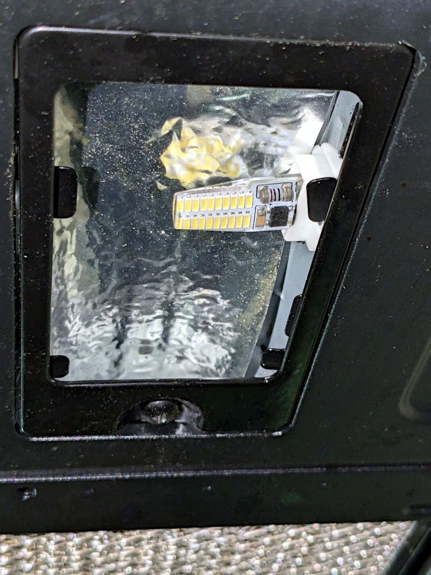
Those are not the best bulbs for the application, as they’re allegedly equivalent to 20-25 W halogens, but I had some on hand from a previous relamping project and they seemed promising.
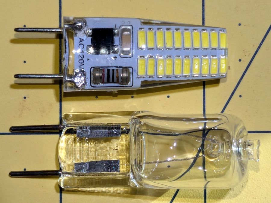
G8 halogens have a flattened section just above the pins that these G8 LED bulbs lack:
G8 halogen vs LED bulb – front view
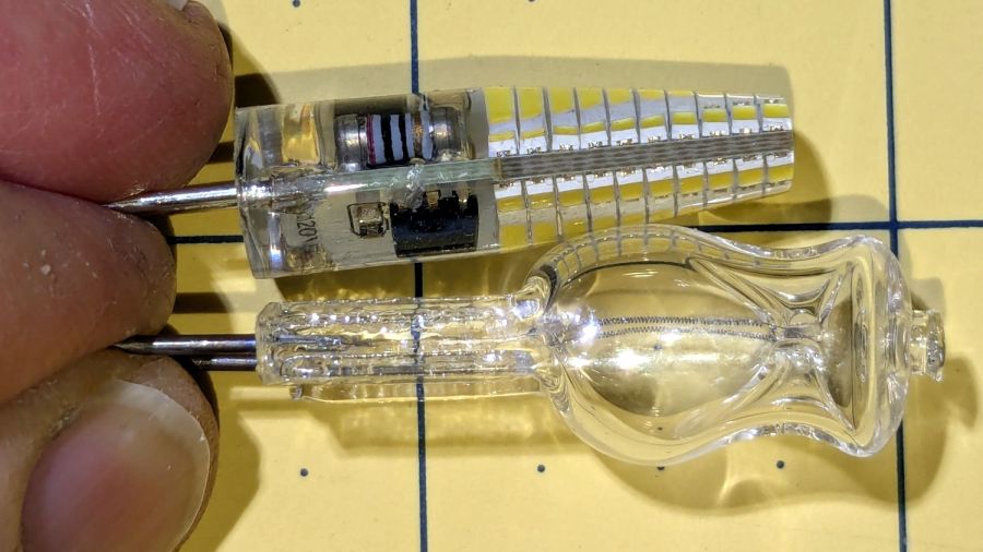
It’s more obvious from the side:
G8 halogen vs LED bulb – side view
The curvature of the soft silicone LED body magnifies the components to look like they fill all the available space, but a little deft X-acto knife work flensed the body down to fit the microwave’s ceramic socket without exposing any of the electrical innards.
Because the LEDs dissipate only 3 W and barely get warm, I replaced the original translucent glass diffuser panels with (yes, laser-cut) clear 3 mm acrylic, then tucked a strip of aluminized mylar above the bulb to bounce some of the light from the upper chips down where it would do more good. I think it’s possible to melt the acrylic with a stovetop mishap, but we don’t make those kinds of recipes.
They’re not daylight shining on the stove, but they’re much brighter than the halogens at maybe 10% of the power.
With the new battery mount & buck converter box installed on Mary’s bike, I updated the running light circuitry to match the ones on my bike. The original wiring just supplied 6.3 V from the headlight circuit, but now the four wire ribbon cable from the electronics box carries 6.3 VDC from the buck converter and a 6 VDC signal going high when the DPC-18 display’s “headlight” output goes active. The latter goes into an optoisolator pulling down Pin 2, telling the running light to stay on continuously.
The optoisolator sits next to the Arduino Nano’s Reset button:
Tour Easy Running Light – unified light top
The black wire barely visible below the optoisolator jumpers Pin 3 to ground, telling the firmware that this is the front running light.
The black & white wires from the top of the optoisolator connect directly to the ribbon cable entering on the other side:
Tour Easy Running Light – unified light bottom
The gray wrap of clear silicone tape mummifies the wire-to-wire soldered connectors.
The firmware now pays attention to the jumper input, so I need only one source file for both front and rear lights:
    if (digitalRead(PIN_POSITION) == HIGH) {
        Blinks = String("i e  ");             // rear = occulting
        Polarity = true;
    }
    else {
        Blinks = String("n e  ");             // front = blinking
        Polarity = false;
    }
This file contains hidden or bidirectional Unicode text that may be interpreted or compiled differently than what appears below. To review, open the file in an editor that reveals hidden Unicode characters.
Learn more about bidirectional Unicode characters
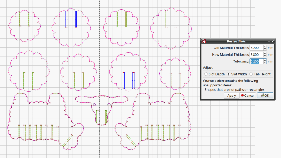
LightBurn includes a Slot & Tab Resizer tool that automagically finds and resizes joints to adapt a design for whatever material thickness you might be using. To judge from the LightBurn forum threads, it doesn’t deal well with random designs fetched from the Interwebs, which suggests those designs were either never intended for laser cuttery or just badly laid out.
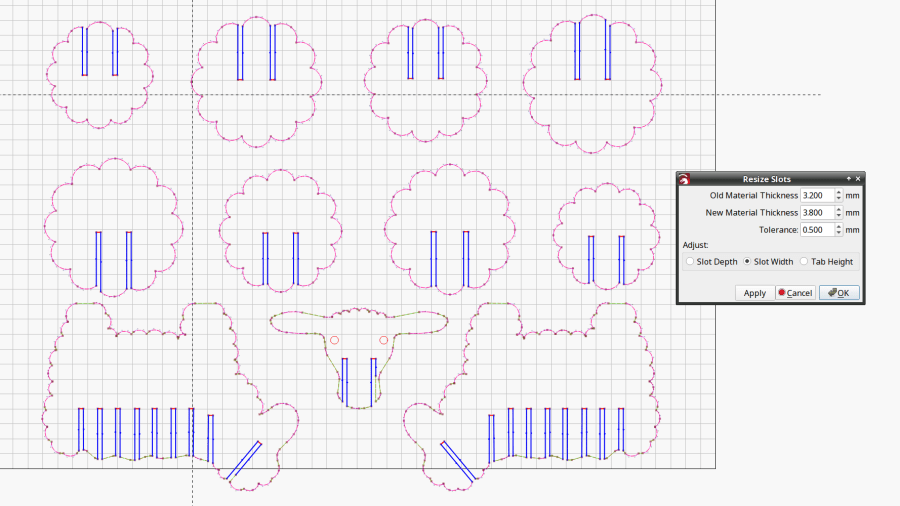
The tool looks for rectangular shapes within the Tolerance of the Old Material Thickness width, then marks their narrow ends with red highlights and their length with blue. Obviously, not all of the slots we humans see count as slots.
A closer look at one of the body shapes with a slightly larger Tolerance shows some of the problems:
Sheep DXF import – body
Using the Node Editor tool reveals two stray nodes near the bottom of the second slot from the left:
Sheep DXF import – slots
Zooming in and blowing out the contrast:
Sheep DXF import – slot bottom
Manually deleting those nodes doesn’t solve the problem, because two more errant nodes lurk at the top of the slot:
Sheep DXF import – slot top
You probably didn’t notice those at first glance, either. Those nodes may be very close together, but they still confuse the issue.
Rather than tracking down and deleting / adjusting those nodes one by one, you can apply the Optimize Shapes tool to squash the superfluous nodes into straight lines:
Sheep DXF import – optimized
Don’t smooth the shapes or fit them to arcs at this point, because both of those operations will round off the corners.
That may still leave a few nodes requiring manual intervention, as on the face shape:
These switches carry absolutely no regulatory approval markings, although they do claim to carry 10 A at 250 V, which I take with another load of salt.
At least here in the US-of-A, a 240 VAC outlet has two “hot” wires carrying 120 VAC 180° out of phase, which means both conductors must be switched. Despite the voltage rating, only the L path goes through the clicky switch, with the N path along a strap just below the switch toggle. Using it on a 240 VAC circuit will kill you stone cold dead should you assume whatever it controls is turned off.
I secured the Line and Neutral conductors with crimp connectors, rather than just wrapping the 20 AWG wires around the screw terminals, because the case halves join without perimeter nesting: a bare millimeter of air in the gap between the halves separates the terminals from my fingers. A layer of good electrical tape on each side improved that situation, but not by much.
The complete lack of strain relief clamping on the cords prompted me to route the wires around the screw bosses. After a function check, squirts of hot melt glue anchored the two cords somewhat better.
Aaaaand I secured that loose strap on the right with an (identical to the others!) screw from the Tray o’ Random Screws. The other switches had both screws installed, so this one must have been a QC escape.
They suffice for the purpose, but … caveat emptor!