The Smell of Molten Projects in the Morning

Ed Nisley's Blog: Shop notes, electronics, firmware, machinery, 3D printing, laser cuttery, and curiosities. Contents: 100% human thinking, 0% AI slop.

Tag: Improvements

Making the world a better place, one piece at a time

  • Laser Cutter: Improved Tube Support Pads

    Laser Cutter: Improved Tube Support Pads

    A recent mirror alignment check led to complete failure at the laser head aperture just upstream of Mirror 3:

    Beam alignment - M3 fail
    Beam alignment – M3 fail

    Those five spots come from the center of the platform and the four corners; they will overlay into a single spot in a properly aligned machine.

    Pondering my options reminded me that I intended to build new laser tube support pads, because the ones shipped inside the machine seemed crudely made:

    CO2 Laser supports - OEM hardware
    CO2 Laser supports – OEM hardware

    It’s partly disassembled in preparation for the next step.

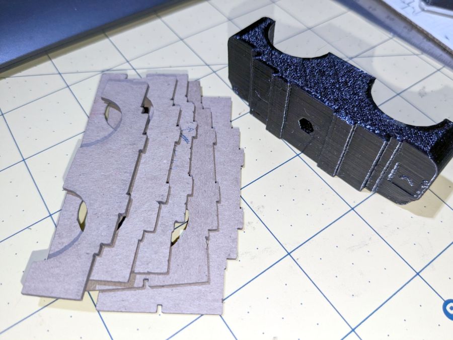
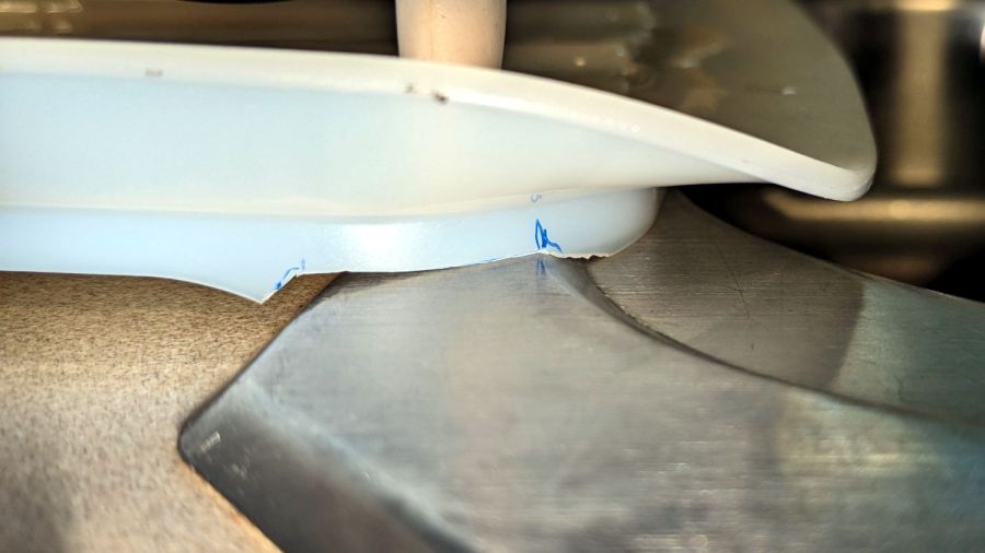
    The chipboard shims underneath the stack are mine, but the OEM pile was unstable even with the screws tightened. The reason became obvious when I took the stack apart:

    CO2 laser supports - OEM molded parts
    CO2 laser supports – OEM molded parts

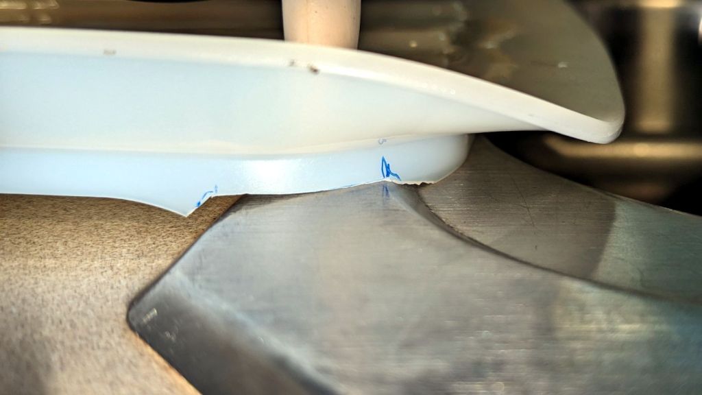
    The bump in the middle of the upper block surrounds the post of the laser tube cradle. It looks like this from the side:

    CO2 Laser supports - OEM tube cradle - side view
    CO2 Laser supports – OEM tube cradle – side view

    All of the blocks were crudely molded and could not be stacked into a stable pile. The tech who assembled and aligned the machine tightened the screws so firmly that the washers crushed into saddles:

    CO2 Laser supports - OEM crushed washers
    CO2 Laser supports – OEM crushed washers

    I can do better than that, if only because I’m not on the clock.

    The tube support on the right end (toward the beam outlet) screwed into a nice set of threaded inserts brazed onto the floor of the laser compartment.

    As far as I can tell, the laser cabinet was intended for a real 60 W tube measuring 1200 mm that would stick out into a box on the side of the cabinet, but would allow the left tube support base (shown above) to screw into a similar quartet of threaded inserts. Instead, it has an overdriven 50 W tube measuring 1050 mm with the left support screwed into four crudely hand-drilled and -tapped holes so far off the centerline as to jam the screws against the front end of their slots in order to get the tube barely into alignment, with the screws on the output side jammed against the rear end of their slots.

    To answer a question you may have: the commercial tube supports one might buy from a reputable supplier (or, for that matter, Amazon) are either exactly as wide as the compartment (thus eliminating one degree of freedom) or obviously unsteady, and would surely require drilling more holes in awkward locations.

    So, we begin.

    The general idea is to make a larger set of blocks fitting another quartet of holes with threaded inserts on the right side of the compartment floor:

    CO2 Laser supports - installed right
    CO2 Laser supports – installed right

    On the right, I stuck the bottom block to the shelf with double-sided tape:

    CO2 Laser supports - installed left
    CO2 Laser supports – installed left

    Because I was unwilling to:

    • Drill and tap holes with the tube in place or
    • Remove the tube to get safer access

    The alert reader will note the four tapped holes immediately to the right of the new blocks. Those were evidently intended for a center tube support for the longer tube, because the crudely hand-drilled holes hide just out of view to the left of the new blocks.

    At the far left of that picture, beyond the two holes probably intended for coolant tubes, you can see one of the four holes with tapped inserts that would match longer tubes, where the 50 W tube has its anode and coolant connections.

    The larger blocks I made have a hole accommodating the bulge in the tube cradle to let it slide back and forth as needed:

    CO2 Laser supports - gluing top layers
    CO2 Laser supports – gluing top layers

    That seemed easier and less exciting than attempting to flycut the bottom of the OEM plastic tube cradle.

    The chipboard layer serves as a guide to keep the tube cradle lined up, with its now much shorter screws into the brass inserts epoxied into the plywood layer.

    I glued the top layers together to get a rigid assembly, with the lower layers being replaceable shims adding up to the right height, whatever that might be. The LightBurn layout has an assortment of useful pieces, some of which I didn’t need:

    Laser tube support blocks - LightBurn layout
    Laser tube support blocks – LightBurn layout

    If this were a greenfield project, the leftmost Base MDF pad would come in handy, as its slots are large enough to clear the flat side of the 4 mm rivnuts I’d install in the compartment floor.

    Thin shims come from paperboard boxes & chipboard:

    CO2 Laser supports - thin shims
    CO2 Laser supports – thin shims

    Thicker spacers come from (scrap) plywood and MDF:

    CO2 Laser supports - thIck shims
    CO2 Laser supports – thIck shims

    Skipping ahead a few days, the tube & mirror realignment came out much better:

    Alignment at Mirror 3 - four corners - 2023-09-02
    Alignment at Mirror 3 – four corners – 2023-09-02

    That’s only the four corners of the platform, but it’s OK by me.

    If you’re fussy, the scorches are all low by a bit under 2 mm. Fixing that requires raising the tube by 2 mm, which I can certainly do, but I’m going to let this whole affair mellow out for a while.

    The LightBurn SVG layout as a GitHub Gist:

    Loading
    Sorry, something went wrong. Reload?
    Sorry, we cannot display this file.
    Sorry, this file is invalid so it cannot be displayed.

  • Laser Cutter: Mirror Pin Wrench

    Laser Cutter: Mirror Pin Wrench

    After struggling with pin pliers again, I finally made a pin wrench for the laser cutter’s mirror retaining rings:

    Laser Mirror Pin Wrench - in use
    Laser Mirror Pin Wrench – in use

    The odd grayish tint toward the flat end of the knob comes from residual black filament in the hot end after switching to retina-burn orange PETG.

    The solid model looks about like you’d expect:

    Mirror Pin Wrench - Solid Model
    Mirror Pin Wrench – Solid Model

    The pins are snippets of 3/32 inch = 2.4 mm steel rod with ground-round ends to fit the 2.5 mm pin sockets in the retaining ring.

    They’re rammed into place with a drill press to keep them aligned with the holes:

    Laser Mirror Pin Wrench - pin insertion
    Laser Mirror Pin Wrench – pin insertion

    Pressed flush with the central boss that aligns the wrench with the ring:

    Laser Mirror Pin Wrench - pin leveling
    Laser Mirror Pin Wrench – pin leveling

    Then put the ring on the bench, set the wrench atop the ring with the pins in the sockets, and press firmly to seat the pins to the proper depth. The end results should look like this:

    Laser Mirror Pin Wrench - mirror ring test
    Laser Mirror Pin Wrench – mirror ring test

    The next time I clean the mirrors, there will be less muttering.

    The OpenSCAD source code as a GitHub Gist:

    // OMTech laser cutter mirror pin wrench
    // Ed Nisley – KE4ZNU – August 2023
    // From https://www.thingiverse.com/thing:4146258
    use <knurledFinishLib_v2_1.scad>
    /* [Hidden] */
    ThreadThick = 0.20;
    ThreadWidth = 0.40;
    HoleWindage = 0.2; // extra clearance
    Protrusion = 0.1; // make holes end cleanly
    inch = 25.4;
    //———————-
    // Dimensions
    /* [Knob] */
    PinDia = 2.4; // pin diameter
    PinOC = 20.5; // … on-center spacing
    PinDepth = 10.0; // … hole depth
    LocDia = 14.5; // central stud
    LocLength = 3.0;
    ShaftDia = 26.0; // un-knurled section diameter
    ShaftLength = 15.0; // … length
    KnurlDia = 30.0; // diameter at midline of knurl diamonds
    KnurlLen = 20.0; // … length of knurled section
    /* [Hidden] */
    KnurlDPNom = 32; // Nominal diametral pitch = (# diamonds) / (OD inches)
    DiamondDepth = 0.5; // … depth of diamonds
    DiamondAspect = 2; // length to width ratio
    KnurlID = KnurlDia – DiamondDepth; // dia at bottom of knurl
    NumDiamonds = ceil(KnurlDPNom * KnurlID / inch);
    echo(str("Num diamonds: ",NumDiamonds));
    NumSides = 4*NumDiamonds; // 4 facets per diamond
    KnurlDP = NumDiamonds / (KnurlID / inch); // actual DP
    echo(str("DP Nom: ",KnurlDPNom," actual: ",KnurlDP));
    DiamondWidth = (KnurlID * PI) / NumDiamonds;
    DiamondLenNom = DiamondAspect * DiamondWidth; // nominal diamond length
    DiamondLength = KnurlLen / round(KnurlLen/DiamondLenNom); // … actual
    TaperLength = 0.75*DiamondLength;
    KnobOAL = ShaftLength + KnurlLen + 2*TaperLength;
    //———————-
    // Useful routines
    module PolyCyl(Dia,Height,ForceSides=0) { // based on nophead's polyholes
    Sides = (ForceSides != 0) ? ForceSides : (ceil(Dia) + 2);
    FixDia = Dia / cos(180/Sides);
    cylinder(r=(FixDia + HoleWindage)/2,
    h=Height,
    $fn=Sides);
    }
    //- Build it
    difference() {
    union() {
    render(convexity=10)
    translate([0,0,TaperLength])
    knurl(k_cyl_hg=KnurlLen,
    k_cyl_od=KnurlDia,
    knurl_wd=DiamondWidth,
    knurl_hg=DiamondLength,
    knurl_dp=DiamondDepth,
    e_smooth=DiamondLength/2);
    color("Orange")
    cylinder(r1=ShaftDia/2,
    r2=(KnurlDia – DiamondDepth)/2,
    h=(TaperLength + Protrusion),
    $fn=NumSides);
    color("Orange")
    translate([0,0,(TaperLength + KnurlLen – Protrusion)])
    cylinder(r2=ShaftDia/2,
    r1=(KnurlDia – DiamondDepth)/2,
    h=(TaperLength + Protrusion),
    $fn=NumSides);
    color("Moccasin")
    translate([0,0,(2*TaperLength + KnurlLen – Protrusion)])
    cylinder(r=ShaftDia/2,h=(ShaftLength + Protrusion),$fn=NumSides);
    color("Brown")
    translate([0,0,KnobOAL – Protrusion])
    cylinder(r=LocDia/2,h=(LocLength + Protrusion),$fn=NumSides);
    }
    for (i=[-1,1])
    translate([i*PinOC/2,0,KnobOAL – PinDepth])
    rotate(180/6)
    PolyCyl(PinDia,PinDepth + Protrusion,6);
    }

    It descends from a long line of similar things dating back to the OG Sherline Speed Wrenches.

  • Onion Maggot Fly vs. Sticky Traps: Season 3 Finale

    Onion Maggot Fly vs. Sticky Traps: Season 3 Finale

    The six sticky traps guarding Mary’s onion beds in her Vassar Community Gardens plots collected this assortment of critter and mulch from mid-July through mid-August, when she harvested the last of the crop:

    • VCCG Onion Maggot Trap A
    • VCCG Onion Maggot Trap B
    • VCCG Onion Maggot Trap C
    • VCCG Onion Maggot Trap D
    • VCCG Onion Maggot Trap E
    • VCCG Onion Maggot Trap F

    The labels do not match those on the first set through mid-July, because I don’t care quite enough to keep track of them.

    The traps don’t collect many onion maggot flies, which suggests that a little control goes a long way. As far as she’s concerned, these traps work very well, because the crop has very little maggot damage.

    Searching for onion sticky traps will produce the rest of the collection. Contact me for the full resolution images, should you need to ID all the critters.

  • Popsicle Mixing Sticks

    Popsicle Mixing Sticks

    Perhaps popsicle stick mixers?

    Popsicle stick mixer - in action
    Popsicle stick mixer – in action

    I made a batch to see if they’d simplify mixing my usual tiny batches of epoxy … and they do! Now I need not worry about forgetting to wipe off the screwdriver or cross-contaminating the resin / hardener tubes.

    Reshaping the tip so the laser beam enters at right angles to the stick produced a cleaner cut and a slightly narrower blade:

    Popsicle stick mixer - cutting
    Popsicle stick mixer – cutting

    The fixture and LightBurn template I made for the engraved markers came in handy. Aligning the template to the fixture proceeds as with the larger craft stick garden markers.

    A small holder keeps finished sticks ready for use:

    Popsicle stick mixer - presentation box
    Popsicle stick mixer – presentation box

    I don’t know how long the box originally holding 1000 sticks has been sitting on the shop shelf, but it’s at least half full despite my continuing efforts. Maybe I can get ahead on my holiday gift prep?

    The LightBurn SVG template layout as a GitHub Gist:

    Loading
    Sorry, something went wrong. Reload?
    Sorry, we cannot display this file.
    Sorry, this file is invalid so it cannot be displayed.

  • Newmowa NP-BX1

    Newmowa NP-BX1

    After a year’s service in my Sony AS-30V helmet camera, the Newmowa NP-BX1 lithium cells perform pretty nearly as well as they started out:

    NP-BX1 - Newmowa 2022 - 2023-08
    NP-BX1 – Newmowa 2022 – 2023-08

    Recharging the cells after that test averaged 907 mA·hr within 2%, so they’re still reasonably well grouped.

    The camera burns 1.9 W, so the worst of the cells has a 100 minute runtime = 3.3 W·hr/1.9 W × 60 min/hr,.

    Our usual weekday rides run a little over an hour and I change the batteries during our longer weekend rides, so they rarely see more than an hour’s use.

    A recent 1-¼ hour = 75 minute ride soaked up 687 mA·hr, just about exactly 75% of 907 mA·hr. Gotta love it when the numbers work.

    Surprisingly good performance, given the drama involved in finding those cells. I wonder if that will hold next year when I buy another set?

  • Tour Easy Running Lights: Firmware

    Tour Easy Running Lights: Firmware

    The optoisolator carrying the Bafang controller’s LIGHT signal pulls Pin 2 down to turn the LED on constantly for night riding:

        if (!Morser.continueSending())
            if (digitalRead(PIN_LIGHTMODE) == HIGH)
                Morser.startSending();
            else
                digitalWrite(PIN_OUTPUT,HIGH);      // constantly turn on in headlight mode
    

    That’s the entirety of the program’s loop() function, so there’s not much to the firmware.

    Imagine that: a whole computer devoted to sampling an input bit a zillion times a second and persistently setting an output bit:

    Tour Easy Running Light - Arduino view
    Tour Easy Running Light – Arduino view

    The Morse output to the rear is now “s” rather than “i” for more blinkiness, but I doubt anybody will ever notice.

    The next time I raise the hood on this thing, I’ll add a digital input to select FRONT or REAR mode to get me out of having to remember which hardware goes where.

    The Arduino source code as a GitHub Gist:

    // Tour Easy Running Light
    // Ed Nisley – KE4ZNU
    // September 2021
    // 2023-03 preprocessorize for front/rear lights
    // https://github.com/markfickett/arduinomorse
    #include <morse.h>
    // Bafang headlight output pulls pin low
    #define PIN_LIGHTMODE 2
    #define PIN_OUTPUT 13
    #define FRONT
    #if defined(FRONT)
    #define BLINKS "b e "
    #define POLARITY false
    #elif defined(REAR)
    #define BLINKS "s "
    #define POLARITY true
    #else
    #error "Needs FRONT or REAR"
    #endif
    // second param: true = active low output
    LEDMorseSender Morser(PIN_OUTPUT,POLARITY,(float)10.0);
    void setup()
    {
    pinMode(PIN_LIGHTMODE,INPUT_PULLUP);
    Morser.setup();
    Morser.setMessage(String("qst de ke4znu "));
    Morser.sendBlocking();
    Morser.setSpeed(75);
    Morser.setMessage(String(BLINKS));
    }
    void loop()
    {
    if (!Morser.continueSending())
    if (digitalRead(PIN_LIGHTMODE) == HIGH)
    Morser.startSending();
    else
    digitalWrite(PIN_OUTPUT,HIGH); // constantly turn on in headlight mode
    }

  • Tour Easy Running Lights: Mechanics

    Tour Easy Running Lights: Mechanics

    The running lights have the same general structure as before and fit into the same front and rear holders:

    Tour Easy Running Light - rear installed
    Tour Easy Running Light – rear installed

    I made the recess slightly deeper to provide a bit more protection to the lens:

    Tour Easy Running Light - front installed
    Tour Easy Running Light – front installed

    The lenses have a 10° beam angle, so a few more millimeters of sidewall doesn’t intercept much light.

    The layout doodle grew a few more notes:

    Tour Easy running light - housing dimensions
    Tour Easy running light – housing dimensions

    I had the good idea of boring the tube, knurling the rod, then epoxying the two together before cutting the rod:

    Tour Easy Running Light - heatsink curing
    Tour Easy Running Light – heatsink curing

    Which let the lathe hold them in perfect alignment during curing:

    Tour Easy Running Light - heatsink plug alignment
    Tour Easy Running Light – heatsink plug alignment

    The rod fits through the lathe spindle and I intended to use it as an arbor while turning the tube exterior, then cut the finished heatsink off flush.

    Which really good idea lasted until the next morning, when I looked at the setup and immediately cut the rod flush with the tube. Because reasons, perhaps excess blood in my caffeine stream.

    So I had to finish the heatsink on hard mode right up against the chuck:

    Tour Easy Running Light - turning heatsink rebate
    Tour Easy Running Light – turning heatsink rebate

    Flipping it around and gripping that little rebate to skim the OD down to 25 mm seemed fraught with peril, so I stabilized the open end with a chuck and plenty of oil; the live center was just too big around for the job.

    Dang, I hate it when I screw up a nice plan.

    Then drill various holes on the Sherline and epoxy the circuit support plate:

    Tour Easy Running Light - circuit plate curing
    Tour Easy Running Light – circuit plate curing

    After boring the PVC pipe to 23 mm ID, I made a pair of Delrin fixtures to simplify turning the exterior to 25 mm before parting it off:

    Tour Easy Running Light - turning body OD
    Tour Easy Running Light – turning body OD

    The PVC is so thin the Arduino’s LEDs shine right through:

    Tour Easy Running Light - installed top view
    Tour Easy Running Light – installed top view

    The radioactive green endcap is ordinary laser-cut fluorescent edge-lit acrylic with sunlight through the garage door on the left. I used red acrylic for the taillight to encourage their separate identities.

    The knockoff Arduino Nano fits on one side of the support plate:

    Tour Easy Running Light - Arduino view
    Tour Easy Running Light – Arduino view

    And the current regulator on the other:

    Tour Easy Running Light - current regulator
    Tour Easy Running Light – current regulator

    Because these run from a dedicated 6.3 V step-down regulator, rather than the Bafang controller’s headlight output, the 2.0 Ω sense resistor sets the LED current to 0.8 V / 2.0 Ω = 400 mA, which is pretty close to the LED 1 W spec.

    The white blob at the end of the two ribbon cable wires is the optoisolator pulling down a pin when the LIGHT signal is active, telling the firmware to stop the normal blink pattern and just turn the LED on all the time. This will come in handy if I ever do any night riding.

    The LED is epoxied to the aluminum shell (with metal-filled JB Weld) and the whole affair never gets more than comfortably warm even with the LED running constantly.

    I think they came out All Good™, despite various blunders along the way.