Ed Nisley's Blog: Shop notes, electronics, firmware, machinery, 3D printing, laser cuttery, and curiosities. Contents: 100% human thinking, 0% AI slop.
Tag: Improvements
Making the world a better place, one piece at a time
The sellers have accepted our offer on their house, so over the course of the next couple of months we’ll be moving, then selling this place. Having begun dismantling and packing the contents of the Basement Shop, Laboratory, and Warehouse, my blog-worthy activities will grind to a temporary halt.
Should you or anyone you know be interested in moving to the trendy Hudson Valley region, we have a conveniently located property with a shop-ready basement:
Up to this point, I’d been making coasters with a layer of cork on the bottom, held in place with wood glue (for MDF or plywood tops) or an adhesive sheet (for acrylic or glass). Doing that with a CD produced the bottom coaster:
Laser cut CDs – Foam vs MDF-cork backing – detail
Although the Mariner’s Compass pattern looks like it extends over the edge, you’re looking through the transparent polycarbonate at the deep pits burned nearly through the entire disc at the corners of the triangles where the laser head slows.
Although the MDF layer makes the coaster exceedingly stiff, it also makes it entirely too thick and much too fiddly to assemble.
The top coaster is a Guilloche-patterned CD stuck to an EVA foam disk with an adhesive sheet. A small foam disk fills the hub hole and, not incidentally, covers the adhesive that would otherwise be exposed:
Laser cut CDs – Foam coaster backing
It’s stiffer than I expected and works well unless the mug / glass / cup has a wet bottom. Alas, the small channels cut into the CD’s surface fill up with the liquid sealing the coaster to the mug, so it sticks firmly and follows the mug upward off the table.
But they’re kinda pretty, inexpensive, and easy to assemble, which counts for something.
The laser runs much faster than a drag knife or a diamond engraving tool!
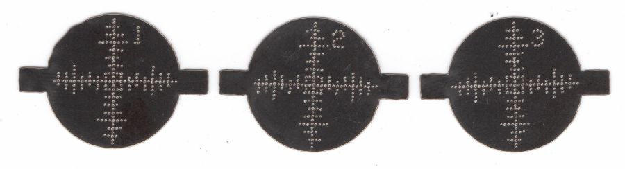
The reddish layer uses Dot mode to draw the legend around the hub:
Laser-engraved CD – legend detail
The characters are 1.5 mm top-to-bottom, with dots just under 0.2 mm diameter on 0.2 mm centers.
Stipulated: there’s no real point to annotating a CD that you’re wrecking, but the code was already there, so why not?
So the overall workflow involves generating an SVG image, importing it into LightBurn with those layers set up with the appropriate cut parameters, using the Three-Point Circle Center Finder tool to align the pattern with the CD, then Fire The Laser. Alignment stops on the laser platform eliminate the need to realign every pattern, so it boils down to running the generator script enough times, importing a batch of patterns, then snapping each one into place and cutting it.
They’re kinda pretty, in the usual techie way:
Laser cut CDs – Guilloche patterns
I have a lot of scrap discs, some ideas of optimizing the process, and a general notion what to do with the prettier results.
The GCMC source code and Bash driver script as a GitHub Gist:
Wrecking scrap discs led to experimenting with the low-power behavior of my nominal 60 W CO₂ laser. I used the same inset version of the Mariner’s Compass quilting pattern as before:
Mariners Compass – stacked insets – LB layout
The KT332N controller is set to a 7% minimum power, as the tube simply doesn’t fire below that level. The power levels shown below are the minimum and maximum for the layer.
The cuts are on CD-R discs with the same general appearance, although I can’t say whether they all came from the same manufacturing lot. All of the cuts are on the clear side of the disc, with the data side flat against the platform. Unless otherwise noted, the pictures are from the clear side, looking down into the trenches carved into the surface, and you can see reflections of the cuts in the aluminized data layer.
Power 7 to 10%:
CD-R vector cut – clear side – 7-10pct
Because the controller uses the minimum power at lower speeds, the laser fails to fire near the corners of the pattern.
Power 8 to 10%:
CD-R vector cut – clear side – 8-10pct
The patterns generally begin in their upper-right corner where the laser has little enough power to prevent melting. However, the tube now continues firing as the laser slows for two other corners and melts a gouge into the surface.
Power 7.5 to 10%:
CD-R vector cut – clear side – 7.5-10pct
The gouges are less prominent, but not by much.
Power 7.1 to 10%:
CD-R vector cut – clear side – 7.1-10pct
Reducing the minimum power to just over the 7% absolute minimum reduces the size of (most of) the blobs, but also causes gaps in some of the lines and at the corners.
Power 7.1 to 7.5%:
CD-R vector cut – clear side – 7.1-7.5pct start
Reducing the maximum power causes the tube to not fire at all for some vectors; it doesn’t fire at all with the maximum power set to 7.1%.
However, the firing is very sensitive to the tube temperature, as that picture is for the first pattern around the disc rim with the cooling water temperature at 20.5 °C.
The last pattern (which is just to the right of the first) looks much better with the coolant at 20.7 °C:
CD-R vector cut – clear side – 7.1-7.5pct end
It’s still not complete, but you can see the tube power has increased enough to melt blobs into the surface similar to those at higher maximum powers.
Power 7.5 to 8%:
CD-R vector cut – clear side – 7.5-8pct
Although the tube now fires continuously throughout the pattern, you can see thinner sections in the longer vectors over on the left.
All of the pictures above are using assist air at 12 l/min, so there’s a stiff breeze blowing the smoke away from the laser beam. Turning the assist air off reduces the flow to 2 l/min and produces a much larger cloud of fumes over the surface that seems to deposit more crud around the vectors:
CD-R vector cut – 2l-min assist air
The small MDF stops jammed in the honeycomb platform let me put all the CD-Rs at the same spot and reuse the same pattern with slight power variations and no realignment. It’s not perfect, but it’s pretty good.
CD-R vector cut – clear side – 7.5-8pct low air cleaned
If you’re being fussy about cleanliness, you might avoid scratching the otherwise pristine surface.
I also burned the data side of a disc to wreck the lacquer and aluminized layer, rather than just the clear polycarbonate.
Power 7.5 to 8% on data side, as seen from the data side:
CD-R vector cut – data side – 7.5-8pct data side
The same pattern on the same disc, seen from the clear side:
CD-R vector cut – data side – 7.5-8pct clear side
Burning through the lacquer and aluminum produces a narrower trench and slightly smaller blobs at the junctions.
Running near the tube’s minimum power produces unpredictable results, because the tube temperature matters. Variations of a few tenths of a degree can prevent the tube from firing, either intermittently or completely, so keeping the minimum layer power well above the minimum tube power is a Good Idea™ unless you can afford considerable scrap.
It’s a slow way to wreck discs, but a nice way to produce suncatching coasters:
Pretty much as expected, the cheap craft adhesive sheet turned out to be inadequate to the task of holding the thin upper border ring onto the clutter collector:
Layered Acrylic Desk Junk Collector – overview
So I stripped the adhesive off with naptha and arranged a cut in a 3M 300LSE acrylic adhesive sheet:
Desk clutter plate – 300LSE adhesive sheet
Four small tabs held that ring to the central piece while I stuck the acrylic ring on it, which turned out to be easy enough. Then I cut the tabs, peeled the paper off the other side, stuck the ring to the plate, and it’s once again ready for clutter.
The bond is visibly better when viewed through the top of the ring, so I think the 300LSE adhesive is thicker and gooier than the craft sheet adhesive, which isn’t surprising at all.
For reasons that will become relevant later on, I must clear the magazines from about ten feet of shelf space (and a stack of boxes), including this assortment:
To the best of my knowledge and belief, each collection is complete within those dates, although I’m equally sure an issue or two went walkabout over the course of four decades.
Having written columns for Digital Machinist, DDJ, and Circuit Cellar, I (still!) have multiple “author’s copies” of those, although I haven’t dug through the boxes for the specifics.
Here’s the deal:
You must take all of any set
Any offer ≥ $0.00 is acceptable
Shipping from ZIP 12603 is your problem
N.B.: Shipping Is Not My Problem (*)
Best offer on or before 30 November 2023 takes any or all.
Whatever remains becomes mulch in December 2023.
(*) A USPS Medium Flat Rate box (11×8.5×5.5 inch) costs $17 within the continental US and holds two or three dozen issues. Obviously, that’s the wrong way to ship an entire shelf of magazines, but gives you an idea of the scale.
If you want to pick ’em up in person, I’ll help heave ’em into your trunk.
Quite a while ago I’d added another LED strip to the under-cabinet light array, because the little cutting boards & suchlike on a wire shelf blocked the light, but fastened it in place with ugly wire ties.
Finally I found a Round Tuit on the desk for brackets mounting the strip directly to the shelf:
Kitchen Light Bracket – shelf blocks – solid model
Ram a pair of brass inserts in the holes, screw the strip in place, snap the brackets between the wires, and it’s much better:
Kitchen Light Bracket – installed
Stipulated: those wire ends look awful. Fortunately, they’re normally hidden by the cutting boards and suchlike on the shelf.
Although it looks precarious, the rounded sides (seem to) have enough grip on the wires to hold the LED strip in place. We’ll see how well that works in practice, but the idea was to avoid anything sticking up above the wires to collide with the stuff on the shelf.
The blocks emerge from a chunk of code glommed onto the original OpenSCAD program: