Ed Nisley's Blog: Shop notes, electronics, firmware, machinery, 3D printing, laser cuttery, and curiosities. Contents: 100% human thinking, 0% AI slop.
Tag: Improvements
Making the world a better place, one piece at a time
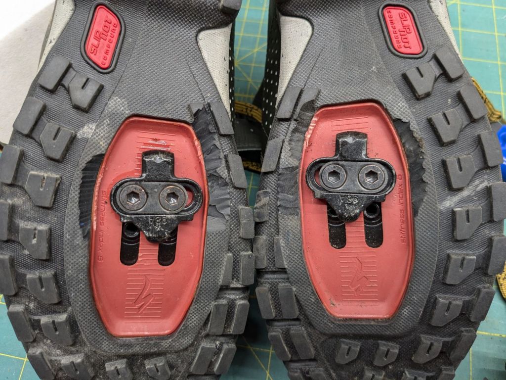
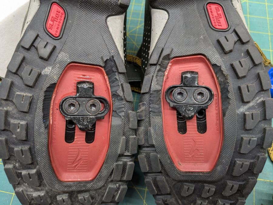
As before, the sole & lugs on Mary’s new Specialized cycling shoes requires too much torque to release the cleat, so I once again carved off everything that got in the way:
Cycling shoe sole carving
A field test prompted a little more carving, but you get the general idea.
This surely affects the shoes’ lateral stability, but getting her feet out of the cleats when & where needed outweighs everything else.
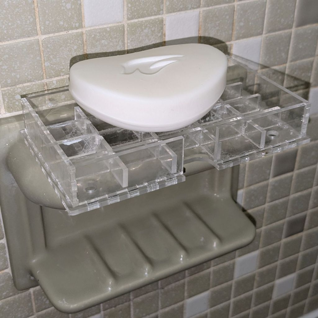
As expected, the adhesive foam strips I used on the bathtub soap tray didn’t survive continued exposure to hot soapy water, so Version 2 includes hooks securing it to the ceramic soap tray and a few other tweaks:
Bathtub Soap Tray – V2 – LightBurn layout
The view from the top:
Soap Tray V2 – top
The hooks are more visible from the bottom, as is the 10 AWG copper wire preventing the whole affair from rotating around the ceramic handle from the weight of the soap bar:
Soap Tray V2 – bottom
Ignore the usual crud you’ll find on your ceramic soap tray, too.
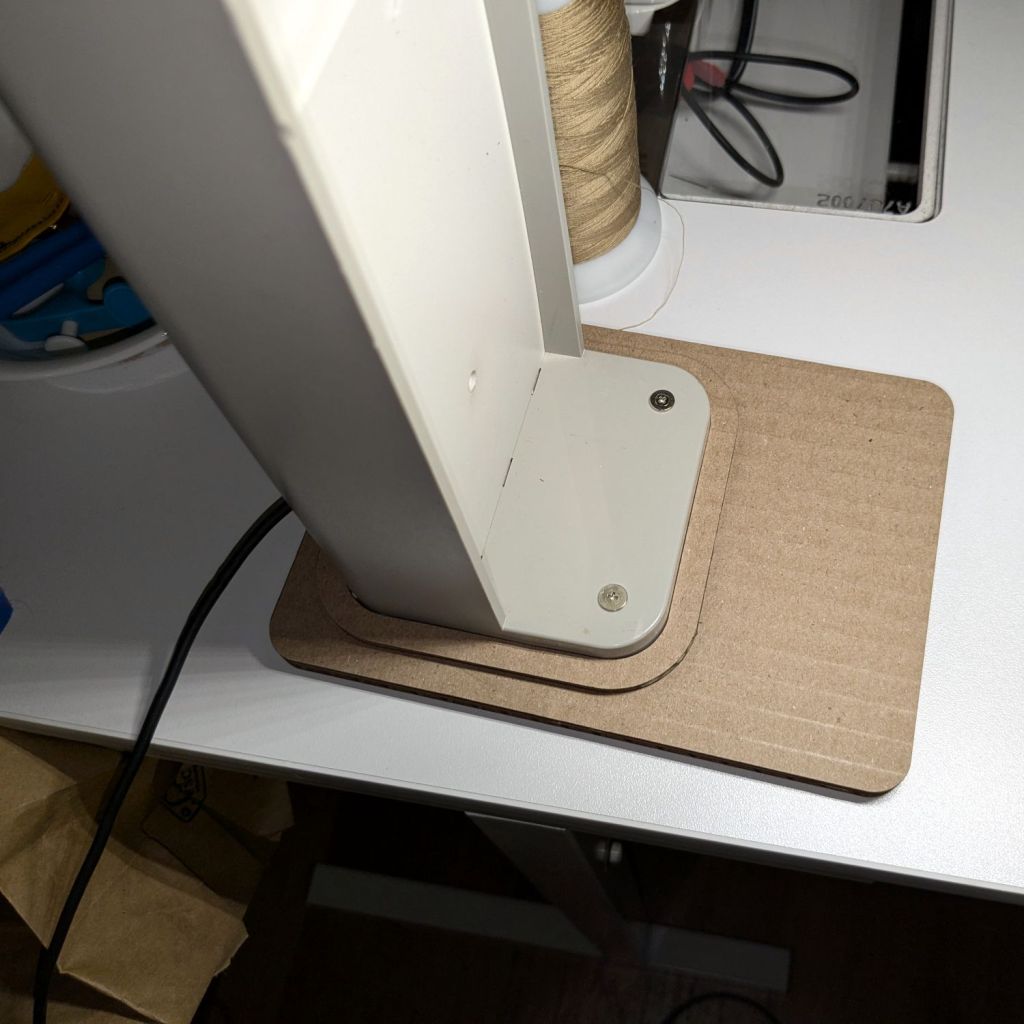
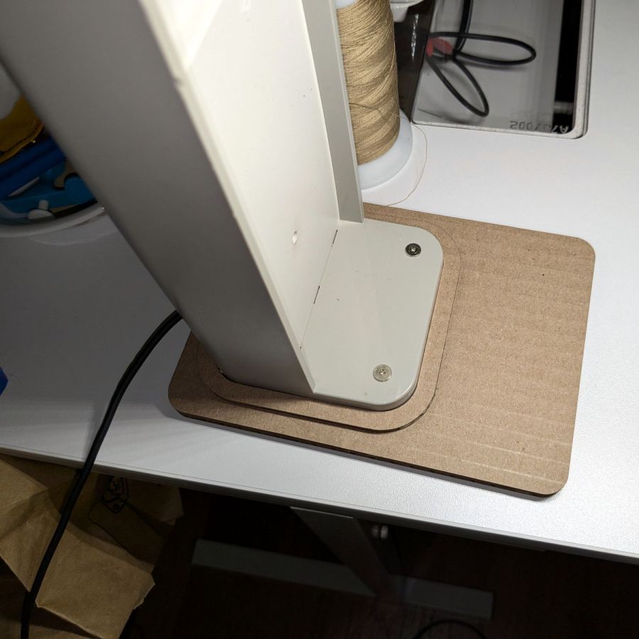
It’s not particularly elegant, what with being cardboard, but it’s a proof of concept that will determine the final size.
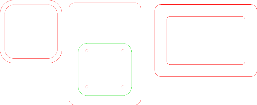
The top layer is a ring around the lamp pedestal for a bit of stabilization protecting the four M3 screws holding the base to the lamp. Those screws sit on a 60 mm square, offset 1 mm to the front of the lamp:
NisLite Baseplate – LightBurn layout
Which explains why I typically make the first few versions of anything out of cardboard.
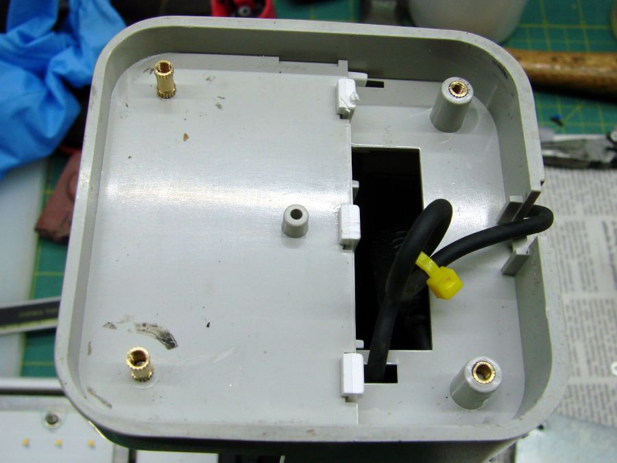
For the record, those inserts look like this:
Converted Ottlite – brass inserts
A pair of very flat-head M3 screws hold the front inserts in place through holes match-drilled in the remains of the bosses I’d long ago epoxied in place. I pressed the rear inserts in place by misusing the drill press, as the lamp is much too tall for the heat setter.
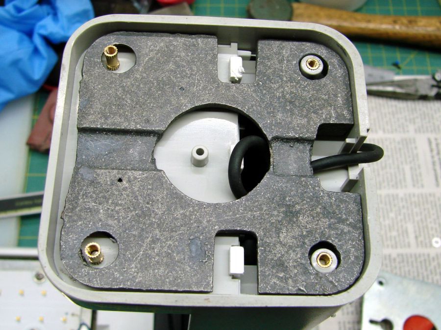
Then comes the iron base weight:
Converted Ottlite – iron weight
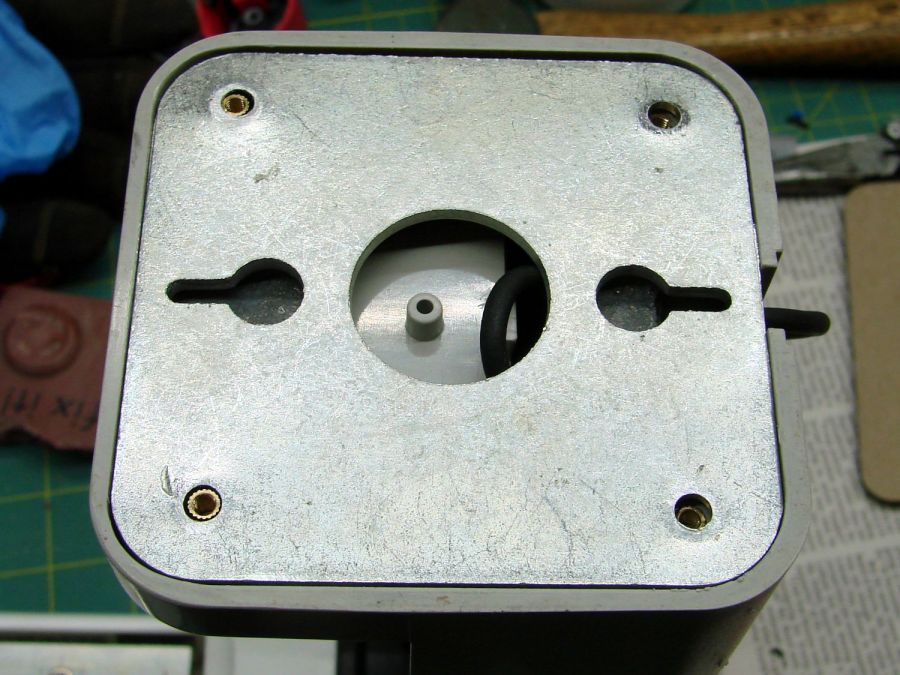
And then the steel outer plate:
Converted Ottlite – steel cover plate
The new base plate gets a ring around its perimeter for clearance under the four pan head M3 screws into the inserts.
If the cardboard base is stable enough, we’ll do an acrylic version in cheerful primary colors.
The LightBurn layout in SVG format as a GitHub Gist:
The general idea of a light box is (wait for it) a uniform background in a box full of bright light:
Light Box – overview
Obviously, this is a low-budget light box, but it makes perfect sense if you already have an essentially unlimited supply of moving boxes, 11×17 inch plotter paper, and a couple of photo / video lights lying around.
A two-layer cardboard ring glued to the top keeps the light from sliding off the box and stiffens the gaping hole letting the light shine through.
You’d normally use a fabric background to get rid of those ugly gaps around the edges and a larger box would be better, so this is along the lines of a proof-of-concept.
In this day and age, you’d normally use a phone camera:
Light Box – gears overview – DOF
The lens on my Pixel 6a has a fixed focal length (around 4.4 mm = 27 mm equivalent) and a fixed f/1.8 (-ish) aperture, producing a razor-thin depth of field at the rear of the front gears. Note the fuzzy gears in the background, all of three inches away, and the slightly fuzzy front edge of the front gears. The camera’s digital zoom doesn’t help matters in the least, despite the AI-powered interpolation.
Keeping things close together helps, although the far end of the wipe towers and the rear of the gears lose detail:
Light Box – gears stacked
Looking from above also helps a little, but a top viewing port would reduce the skewed perspective:
Light Box – gears detail – DOF
Shallow DOF keeps your attention on the foreground, which is why real photographers use it for portraits:
Light Box – gears standing – DOF
The camera, an ancient Sony DSC-H5 with a zoom lens going down to f/8, still does nice work through a 2× macro adapter lens:
Light Box – gear detail – top light
The DOF is still narrow, but at least the entire front gear is in focus.
Adding a front light picks out the knurling:
Light Box – gears detail – front light
The results definitely look better than before, but it’ll take a bit of getting used to traipsing to the Basement Laboratory for every photo …
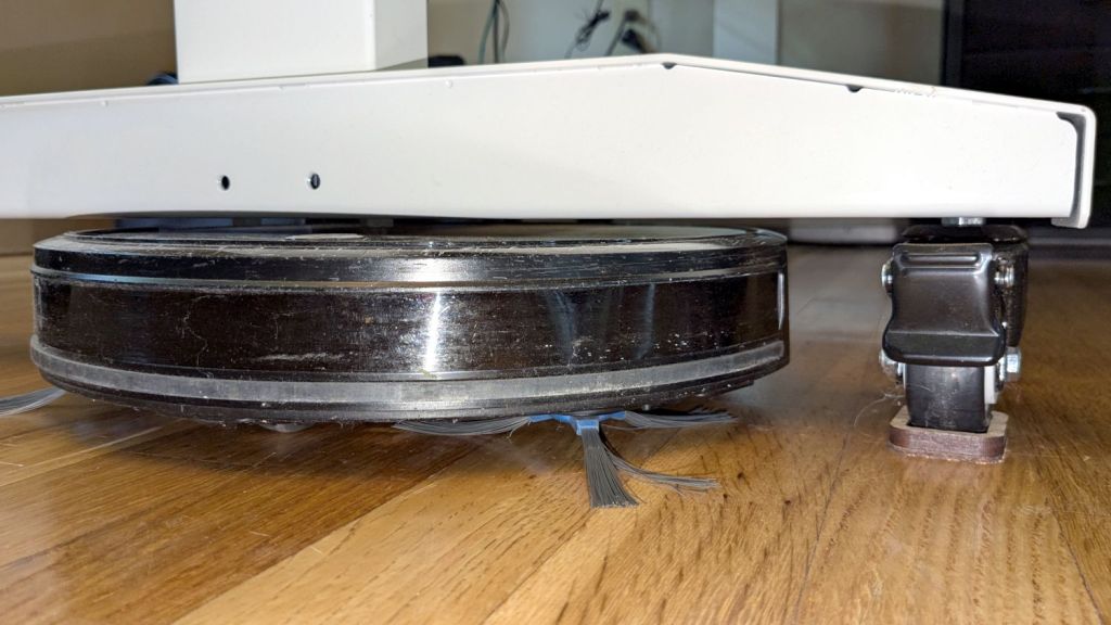
The flat robot vacuum assigned to clean the floors around here would occasionally get stuck under the leg of my Husky workbench-as-desk and fail to complete its mission. Living in the future makes solving that problem a matter of minutes:
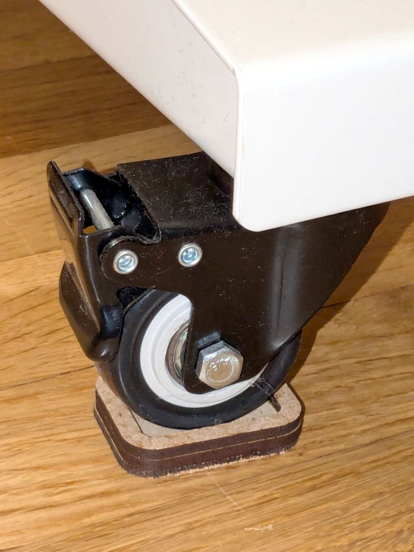
Husky workbench caster feet – installed
The upper rim captures the locked-in-place wheel in a 35×25 mm recess atop the middle 45×35 mm slab, with a 2.5 mm cork layer on the bottom. Laser-cut, of course, glued with ordinary yellow wood glue, and clamped for about half of a Squidwrench remote meeting.
Raising the desk by 5.5 mm gives the Flat One juuust enough clearance to scuttle under there:
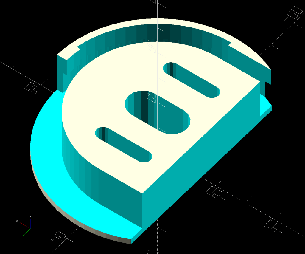
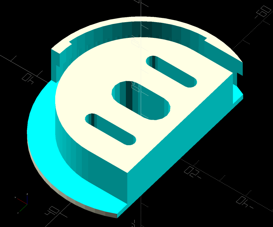
A small tweak to the venerable spoon drainer adds a configurable cutout adapting it to a slightly different dish drainer rack:
Measuring Spoon Drainer – solid model
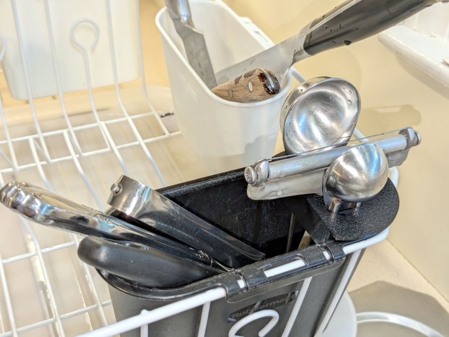
Which lets it snuggle into the corner:
Measuring spoon drainer – installed
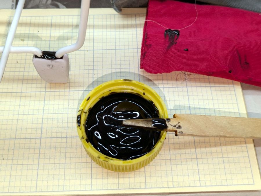
Both the old and new racks had coated steel loops stuck into rubberoid feet perfectly suited to collect water and eventually rust the loops. Given a new rack, I figured potting the feet in JB PlasticBonder urethane adhesive would help forestall the rust:
Rubbermaid dish drainer – foot potting
I wish it were white, rather than black, but the only other color choice is tan and I can’t wish nearly that hard.
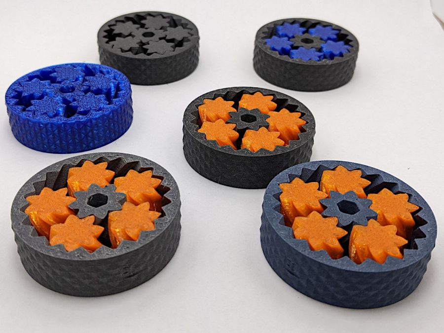
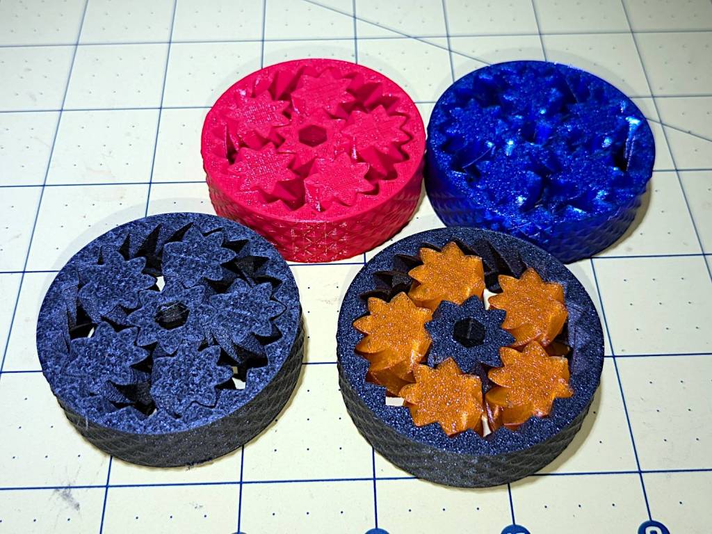
So I loaded up the same STL in Prusaslicer and made three more:
Planetary Gear Bearing – M2 vs MK4
Both pictures show the same red bearing, done in PLA on the Makergear M2. The other bearings are PETG and PETG-CF on the Prusa MK4 + MMU3.
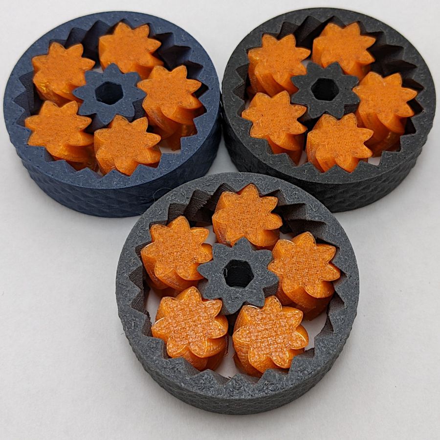
The blue bearing has about 5 mm of axial play, a bit more than the red.
The gray bearing is PETG-CF and has maybe 1 mm of axial play, which agrees with my original observation that an Extrusion Multiplier of 1.0 results in slightly overstuffed carbon fiber parts. It’s not much and, frankly, produces a better fit in this case, but it’s different than pure PETG. Which should come as no surprise, of course, given that it’s 15% carbon.
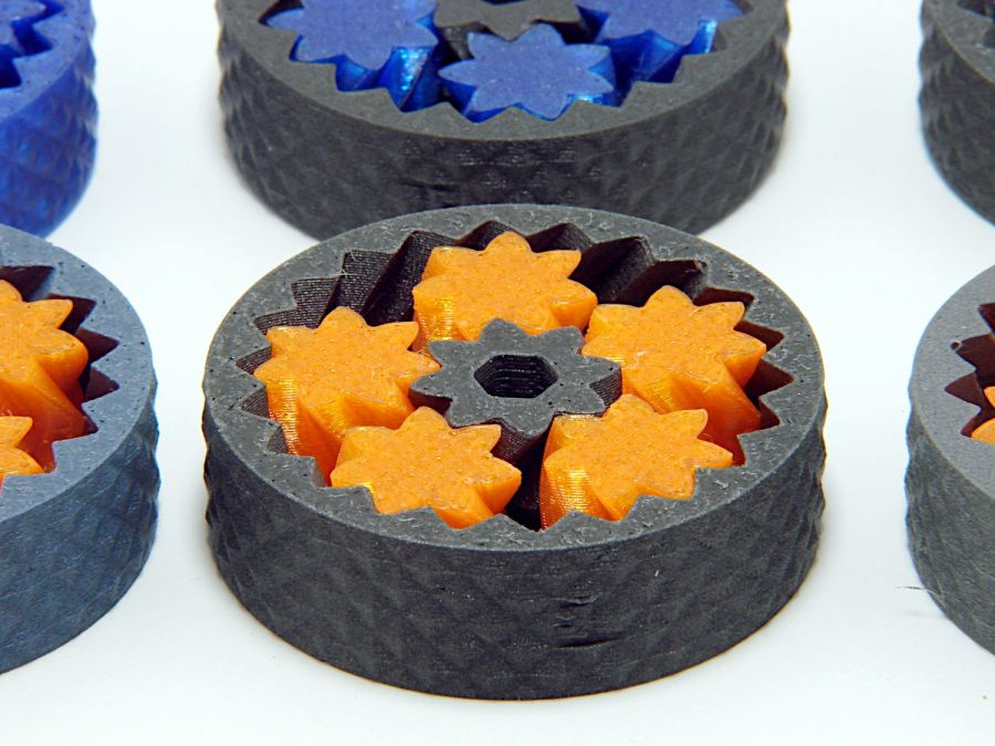
The gray-and-orange bearing looks spectacular in person and has about 3 mm of axial play, roughly the same as the red bearing, which you’d expect from overstuffed PETG-CF and pure PETG.
The single-color bearings print in about 1.5 hours and the two-color one weighed in over four hours. Multi-material objects are do-able, but you gotta want the results.
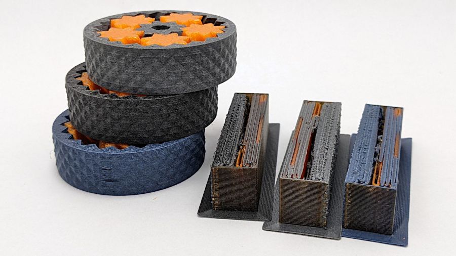
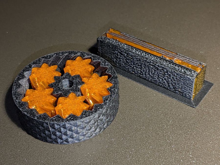
I told Prusaslicer to wipe the orange filament into the gray infill during color changes (per the Wipe Tower doc), but those two gray parts have so little infill as to make no difference:
Planetary Gear Bearing – PETG PETG-CF with wipe tower
The wipe tower in that posed photo has a nubbly texture because the filament just gets squirted without regard to anything other than maintaining the basic tower shape.
Seeing things appear on the platform never gets old!