Ed Nisley's Blog: Shop notes, electronics, firmware, machinery, 3D printing, laser cuttery, and curiosities. Contents: 100% human thinking, 0% AI slop.
Tag: Improvements
Making the world a better place, one piece at a time
A while back I bought a lifetime supply of silica gel beads from Sorbent Systems, with the intent of gradually replacing all of the miscellaneous desiccant packs floating around here. The catch is figuring out how to package 2 mm spherical beads, because the whole point of a desiccant pack is getting moist air in contact with the beads. I’m sure there’s a commercial solution for this out there, but …
Anyhow, here’s what 500 g of beads looks like, captured inside a 12×12 inch square of landscaping cloth folded in half:
Silica gel in landscape cloth bag
It really should be sewn along the three joined edges, but this is a quick-and-dirty prototype to see how it works; I simply folded the edges over twice and stapled through all six layers.
For the record, 500 g of beads occupies 700 ml in the measuring cup I used to weigh and pour them into the end of the bag. The bag + beads + staples weighs 508 g. The can holding the bulk beads has a humidity indicator card that shows the humidity is below 10%, so I’ll assume they’re pretty well dehydrated.
It’s now in the basement safe, presumably soaking up moist air at a frantic pace. I’ll check it in a week or two and see what’s actually happening.
For the record, those old desiccant granules (and their tray) weighed 853 g when they went into the safe and emerged at 916 g, having soaked up 63 g = 2 oz of water over the last five months.
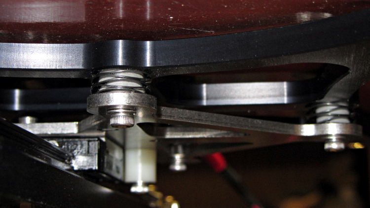
The M2’s build platform consists of an 8×10 inch glass slab atop an aluminum spider, all supported by a trio of fairly stiff springs. Back when I was experimenting with excessive acceleration, I inserted some silicone rubber cylinders to boost the spring constant and stabilize the platform
I removed the screws and springs one by one, tucked a cylinder inside the spring, and reinstalled it:
Silicone rubber pads for M2 platform – installed
The trick is to park the nozzle near the edge of the platform where it will rise without the screw holding it down, measure the distance twixt nozzle and platform, lower the platform by a (known!) 50 mm, install the cylinder, raise the platform, then tweak the screw to put the same distance between the nozzle and the platform as you started with.
This probably doesn’t make much difference with the default 3 m/s2 acceleration, but up around 10 m/s2 it seemed wobbly. No suprise: that’s over 1 G of lateral acceleration and the platform weighs a pound or so.
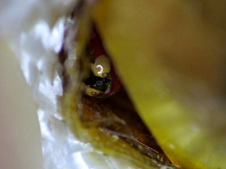
The stock Makergear M2 hot end uses a 100 kΩ thermistor for temperature sensing. A wrap of Kapton tape holds it against the brass nozzle, with a stretchy fiberglass-lined tube for protective insulation and a bit of pressure. This picture shows the tape pocket around the thermistor, with my thumbnail on the left:
The RAMBo board in the M2 has four thermistor inputs and no thermocouple inputs, which surely drove the decision to use themistors. I want to use thermocouples with the LinuxCNC controller, because they’re more compact and happier at higher temperatures.
So I unwrapped the nozzle and lined up a thermocouple beside the thermistor:
M2 – extruder – thermistor-thermocouple
Where a dab of JB Weld firmly bonds them to the nozzle:
M2 – extruder – epoxied sensors
As nearly as I can tell, the JB Weld that I used on the Thing-O-Matic is still going strong. I think the trick is to not apply mechanical force to the bond when it’s hot; secure the leads firmly and use the epoxy only as a thermal connection. Yes, you can get fancy higher-temperature adhesives, but this seems to work well enough.
For the moment, I’m using ordinary cotton cloth secured with Kapton tape as insulation:
M2 – extruder – cotton insulation
The brown dot that looks like a bead is actually a flat stain on the nozzle.
Part of becoming an engineer involves discovering the difference between what works and what doesn’t, with the goal of doing more of the former and less of the latter. In tech fields, gaining such knowledge requires observations, records, and graphs.
The alert reader may recognize the understated presence of a guiding hand, here and there, in some projects. I needed one, too, back in the day, even if I didn’t appreciate it (by at least the same amount). Fortunately, blogs hadn’t been invented, so you’ll never know.
Because it seems there’s no good support for separate X sessions with dual monitors these days, the landscape and portrait monitors on my desk represent viewports into a larger pixel array within a single X session. As a consequence, it’s entirely possible to slide windows across the gutter between the two displays (generally producing an essentially unusable result), but one cannot flip through workspaces on only one monitor.
Worse, some programs seem to have trouble remembering that they were last seen on the portrait monitor, so I must rearrange the windows at the start of every session. First world problem, yeah, but still annoying.
I’d previously used devilspie to force windows to their proper places across monitors, sessions, and workspaces, but its s-expression syntax was impenetrable and I eventually gave up using it.
A fork (or continuation or something) called devilspie2 uses lua scripts that I can both read and write. It’s an Ubuntu package and easy to set up.
A typical script in ~/.config/devilspie2 looks like this:
if (get_application_name()=="Firefox") then
   set_window_geometry(0,0,1300,1200);
   maximize_vertically();
end
Putting Adobe Reader on the portrait monitor looks about the same:
if (get_application_name()=="acroread") then
   unmaximize();
   set_window_geometry(2561,0,1000,100);
   maximize();
end
Set /usr/bin/devilspie2 as an auto-started program and it Just Works…
The problem was to get both a landscape and a portrait monitor working. The complexity came from the landscape monitor, a 2560×1440 Dell U2711, which requires either a Dual-Link DVI or HDMI input to reach full resolution. The portrait monitor, an old 1608×1050 Dell 2005FPW, uses Single-Link DVI.
The previous attempt with an nVidia GT430 card failed: both DVI outputs were Single-Link, despite their connector’s appearance. It had worked OK with the previous landscape monitor, a 1600×1200 Dell 2001FP.
So I picked up a low-end nVidia GT610 card that advertised both Dual-Link DVI and HDMI. I plugged the DVI cable into the U2711 and it lit up at full resolution, then I plugged the HDMI into the 2005FPW and it lit right up. By some miracle that didn’t involve tweaking an xorg.conf file, the 2005FPW immediately displayed the pixels lying to the right of the U2711, exactly as I wanted; all I had to do was rotate the image using xrandr.
Not only that, but the version of xsetwacom in Xubuntu 12.10 once again respects the MapToOutput "HEAD-0" option that restricts the stylus to the U2711 monitor. That means I can’t put the GIMP toolbars and suchlike on the portrait monitor, but the U2711 has enough dots to render that moot.
Although the Dell doc strongly suggests that the on-board VGA and Displayport outputs don’t work with a PCI-E video card plugged in, xrandr reports:
Screen 0: minimum 8 x 8, current 3610 x 1680, maximum 16384 x 16384
DVI-I-0 disconnected (normal left inverted right x axis y axis)
VGA-0 disconnected (normal left inverted right x axis y axis)
DVI-I-1 connected 2560x1440+0+0 (normal left inverted right x axis y axis) 597mm x 336mm
   2560x1440      60.0*+
   1920x1200      59.9
   1680x1050      60.0
   1600x1200      60.0
   1280x1024      75.0     60.0
   1280x800       59.8
   1152x864       75.0
   1024x768       75.0     60.0
   800x600        75.0     60.3
   640x480        75.0     59.9
HDMI-0 connected 1050x1680+2560+0 left (normal left inverted right x axis y axis) 434mm x 270mm
   1680x1050      59.9*+
   1280x1024      75.0     60.0
   1152x864       75.0
   1024x768       75.0     60.0
   800x600        75.0     60.3
   640x480        75.0     59.9
I’m not going to connect the DVI-I-0 and VGA-0 outputs; my physical desk has no room for more pixels…
The ~/.xprofile file now looks like:
setxkbmap -option terminate:ctrl_alt_bksp
xrandr --output HDMI-0 --rotate left
xrandr --dpi 100x100
xsetwacom --verbose set "Wacom Graphire3 6x8 stylus" MapToOutput "HEAD-0"
xsetwacom --verbose set "Wacom Graphire3 6x8 eraser" MapToOutput "HEAD-0"
Being that type of guy, my Start and End G-Code routines are somewhat more elaborate than usual…
The Start routine handles homing, which is more dangerous than you might think, and wiping the drool off the nozzle:
;-- Slic3r Start G-Code for M2 starts --
;  Ed Nisley KE4NZU - March 2013
M140 S[first_layer_bed_temperature]	; start bed heating
G90				; absolute coordinates
G21				; millimeters
M83				; relative extrusion distance
M84				; disable stepper current
G4 S3			; allow Z stage to freefall to the floor
G28 X0			; home X
G92 X-95		; set origin to 0 = center of plate
G1 X0 F30000    ; origin = clear clamps on Y
G28 Y0			; home Y
G92 Y-125		; set origin to 0 = center of plate
G1 Y-122 F30000    ; set up for prime near front edge
G28 Z0			; home Z
G92 Z1.0		; set origin to measured z offset
M190 S[first_layer_bed_temperature]	; wait for bed to finish heating
M109 S[first_layer_temperature]		; set extruder temperature and wait
G1 Z0.0 F2500	; plug extruder on plate
G1 E10 F300		; prime to get pressure
G1 Z5 F2500		; rise above blob
G1 Y-115 F30000	; move away
G1 Z0.0 F2500	; dab nozzle to remove outer snot
G4 P1			; pause to clear
G1 Z0.1			; clear bed for travel
;-- Slic3r Start G-Code ends --
The fundamental problem with homing is that you don’t know where the nozzle stands in relation to the build platform and the bulldog clips clamping the glass plate to the aluminum heater. If you simply home X and Y with Z unchanged, you will eventually plow the nozzle directly across a clip. Trust me on this, you do not want to do that.
So Line 7 disables the stepper motors. In an ideal world, the Z axis stage would then free-fall to the bottom of the chassis during the 4 second pause produced by the G4 S3 instruction. In the real world, that works most of the time, but the platform sometimes sticks where it is. You don’t want to home the Z axis to the top of its travel, because that will eventually crunch the nozzle into those clips, so I plan to add a bottom limit switch so I can drive the platform to a known location away from everything else.
The default M2 Start G-Code puts the XY origin at the front left side of the platform, following the RepRap convention. Maybe it’s just me, but having the origin in the middle of the platform makes more sense for my objects; most of my OpenSCAD models are more-or-less symmetric, so putting the XY origin at their center works well. Ultimately, it doesn’t matter as long as you’re consistent, but my Start G-Code doesn’t produce the same results as the Makergear setup.
Line 9 homes the X axis and Line 10 sets the coordinate to -95. The X axis home position is about 5 mm from the left edge of the glass plate, so the nozzle has about 195 mm of travel to the right edge of the 200 mm plate. The X=0 origin will be in the middle of the printable range, with -95 mm to the left limit (the home position) and +95 to the right edge; the nozzle can travel another 30 mm beyond the right edge to about +125. Line 11 puts the nozzle in the middle of its travel at X=0.
Line 12 homes the Y axis and Line 13 sets the coordinate to -125. The Y axis home position is almost exactly on the front edge of the 250 mm glass plate, so the Y=0 origin is centered on the plate. The nozzle can travel an additional 10 mm off the rear edge of the plate. Note that you must position the nozzle somewhere on the X axis that avoids the bulldog clips; any of X=±95 or X=0 will work. Line 14 puts the nozzle in the middle of the plate at Y=0; it’s already at X=0, so the plate is now centered.
Line 15 homes the Z axis. I’ve set the limit switch so that the home position leaves exactly 1.0 mm between the nozzle and the glass plate, which I find easier to measure than the Makergear suggestion of 0.1 mm. Of course, that’s because I have a Starret taper gauge in my tool cabinet. Use what you have, but use it consistently.
Line 16 sets the Z axis coordinate position to +1.0 mm, matching the measured height, so that Z=0 corresponds to the nozzle exactly kissing the glass plate. The Makergear defaults put Z=0 about 0.1 mm above the platform; I’d rather apply model- and material-dependent offsets to “natural” machine positions.
All of that ignores Z axis backlash. Some preliminary guesstimates put that around 0.1 mm, far better than my Sherline, but still large with respect to the layer thickness. I need more measurements of that, plus some measurements of the actual glass flatness. I think the glass bows upward by about 0.1 mm in the middle, but that requires better probing that will be easier under LinuxCNC control where I can do automated platform mapping.
With the nozzle parked 1.0 mm over the platform, the next two lines wait for everything to reach the proper temperature. I preheat the platform and crank up the extruder temperature before starting the program , so these steps don’t take too long.
However, the nozzle cools off as the drool contacts the much colder platform (it’s heated to 70 °C, but that’s cooler than 150-ish °C by a considerable margin) and the PID loop struggles to reheat it. I think that’s due to the default I term being only 0.1, which reduces integral windup during preheating, but also slows recovery from a sudden thermal load. It helps to preheat the nozzle about 10 °C over the desired temperature, then let it cool during this step.
M2 – Wipe blobs on glass platform
Line 19 uses Nophead’s trick (which I cannot find now) of planting the nozzle on the plate at Z=0.0 to reduce drool, although I do that after the nozzle reaches extruding temperature. The drool forms a blob on the platform as the nozzle heats, but the nozzle punches directly through it on the way to Z=0.0.
Line 20 runs 10 mm of filament into the hot end to pressurize the extruder. Some of the molten goo oozes out around the nozzle, enlarging the blob on the glass plate. The object of the game is to leave all that behind: having a generous contact patch on the glass helps.
The larger blob on the left of the picture (at Y=-125) comes from that process.
Line 21 starts the wiping dance:
Raise the nozzle above the blob to Z=5 mm
Move away from the blob by 5 mm. I’ll probably change this to move in the +X direction.
Tap the nozzle on the platform, so (almost all of) the molten PLA slides away from the orifice
Get 0.1 mm of clearance from the platform, directly over the new blob
Scoot off to print a Skirt extrusion around the object
The smaller, rather flat, blob on the right comes from the nozzle tap. A thin hair may stretch from the blob to the start of the skirt, but it doesn’t amount to much.
Sometimes, of course, the blobs don’t adhere to the glass plate and accompany the nozzle to the start of the skirt. By the conservation of perversity, that’s also when the skirt starts on the far side of the origin, so the blob smears all over the object’s first layers. The Makergear wipe process extrudes the waste filament over the side of the plate, then shears it off as the nozzle returns to the surface; I’ll try blending that in with my startup sequence at some point.
My slic3r configuration extrudes at least 15 mm of filament into the skirt, giving the extruder plenty of time to reach a steady state before starting the actual object. Generally that’s far more than enough filament, but sometimes … well, it’s a good idea to watch what’s going on.
On the other end of the printing process, the End G-Code routine handles shutdown with the object on the platform:
;-- Slic3r End G-Code for M2 starts --
;  Ed Nisley KE4NZU - March 2013
M104 S0		; drop extruder temperature
M140 S0		; drop bed temperature
M106 S0		; bed fan off
G1 Z195	F2500	; lower bed
G1 X0 Y0 F30000	; center nozzle
M84     	; disable motors
;-- Slic3r End G-Code ends --
Line 3 begins turning the heaters and bed fan off. I’ve unplugged the fan for now, so Line 5 is just for completeness.
Line 6 lowers the bed to the bottom under power, because that’s faster that a free fall and it’s guaranteed to work.
With the object safely out of the way, Line 7 centers the nozzle over the platform.
Finally, Line 8 turns off the steppers off; the platform drops another few millimeters
Then everything cools down. Because I run the platform at well above PLA’s glass transition temperature, it must cool for quite a while until the object stiffens up.