The Smell of Molten Projects in the Morning

Ed Nisley's Blog: Shop notes, electronics, firmware, machinery, 3D printing, laser cuttery, and curiosities. Contents: 100% human thinking, 0% AI slop.

Tag: Improvements

Making the world a better place, one piece at a time

  • Makergear M2: Nozzle Temperature Sensing

    The stock Makergear M2 hot end uses a 100 kΩ thermistor for temperature sensing. A wrap of Kapton tape holds it against the brass nozzle, with a stretchy fiberglass-lined tube for protective insulation and a bit of pressure. This picture shows the tape pocket around the thermistor, with my thumbnail on the left:

    M2 Nozzle Thermistor - as-shipped
    M2 Nozzle Thermistor – as-shipped

    Peeling back the tape a bit shows the thermistor against the nozzle, with the glass bead reflecting the LED ringlight around the macro lens adapter:

    M2 Nozzle thermistor - exposed
    M2 Nozzle thermistor – exposed

    The RAMBo board in the M2 has four thermistor inputs and no thermocouple inputs, which surely drove the decision to use themistors. I want to use thermocouples with the LinuxCNC controller, because they’re more compact and happier at higher temperatures.

    So I unwrapped the nozzle and lined up a thermocouple beside the thermistor:

    M2 - extruder - thermistor-thermocouple
    M2 – extruder – thermistor-thermocouple

    Where a dab of JB Weld firmly bonds them to the nozzle:

    M2 - extruder - epoxied sensors
    M2 – extruder – epoxied sensors

    As nearly as I can tell, the JB Weld that I used on the Thing-O-Matic is still going strong. I think the trick is to not apply mechanical force to the bond when it’s hot; secure the leads firmly and use the epoxy only as a thermal connection. Yes, you can get fancy higher-temperature adhesives, but this seems to work well enough.

    For the moment, I’m using ordinary cotton cloth secured with Kapton tape as insulation:

    M2 - extruder - cotton insulation
    M2 – extruder – cotton insulation

    The brown dot that looks like a bead is actually a flat stain on the nozzle.

    The insulation should become something more suited for high temperatures, perhaps the ceramic fiber I used on the Thing-O-Matic, but cotton will suffice for now.

    Now, wisely is it written that a man with one thermometer knows the temperature, while a man with two thermometers is never certain…

  • Monthly Science: Larval Engineer

    Part of becoming an engineer involves discovering the difference between what works and what doesn’t, with the goal of doing more of the former and less of the latter. In tech fields, gaining such knowledge requires observations, records, and graphs.

    Our Larval Engineer is off to a good start, having collected her projects & notes into blog format.

    The alert reader may recognize the understated presence of a guiding hand, here and there, in some projects. I needed one, too, back in the day, even if I didn’t appreciate it (by at least the same amount). Fortunately, blogs hadn’t been invented, so you’ll never know.

    Karen at the lathe
    Karen at the lathe

    You may enjoy her story of the Taxi Horn project, which you see here in the lathe.

    Memo to Self: After launch, guiding hands must remain with the gantry. One must Just. Let. Go.

  • Dual Monitors: devilspie2 FTW!

    Because it seems there’s no good support for separate X sessions with dual monitors these days, the landscape and portrait monitors on my desk represent viewports into a larger pixel array within a single X session. As a consequence, it’s entirely possible to slide windows across the gutter between the two displays (generally producing an essentially unusable result), but one cannot flip through workspaces on only one monitor.

    Worse, some programs seem to have trouble remembering that they were last seen on the portrait monitor, so I must rearrange the windows at the start of every session. First world problem, yeah, but still annoying.

    I’d previously used devilspie to force windows to their proper places across monitors, sessions, and workspaces, but its s-expression syntax was impenetrable and I eventually gave up using it.

    A fork (or continuation or something) called devilspie2 uses lua scripts that I can both read and write. It’s an Ubuntu package and easy to set up.

    A typical script in ~/.config/devilspie2 looks like this:

    if (get_application_name()=="Firefox") then
       set_window_geometry(0,0,1300,1200);
       maximize_vertically();
    end
    

    Putting Adobe Reader on the portrait monitor looks about the same:

    if (get_application_name()=="acroread") then
       unmaximize();
       set_window_geometry(2561,0,1000,100);
       maximize();
    end
    

    Set /usr/bin/devilspie2 as an auto-started program and it Just Works…

  • Dual Monitors: Dual-Link DVI + HDMI

    Finally, this Just Worked…

    The problem was to get both a landscape and a portrait monitor working. The complexity came from the landscape monitor, a 2560×1440 Dell U2711, which requires either a Dual-Link DVI or HDMI input to reach full resolution. The portrait monitor, an old 1608×1050 Dell 2005FPW, uses Single-Link DVI.

    The previous attempt with an nVidia GT430 card failed: both DVI outputs were Single-Link, despite their connector’s appearance. It had worked OK with the previous landscape monitor, a 1600×1200 Dell 2001FP.

    So I picked up a low-end nVidia GT610 card that advertised both Dual-Link DVI and HDMI. I plugged the DVI cable into the U2711 and it lit up at full resolution, then I plugged the HDMI into the 2005FPW and it lit right up. By some miracle that didn’t involve tweaking an xorg.conf file, the 2005FPW immediately displayed the pixels lying to the right of the U2711, exactly as I wanted; all I had to do was rotate the image using xrandr.

    Not only that, but the version of xsetwacom in Xubuntu 12.10 once again respects the MapToOutput "HEAD-0" option that restricts the stylus to the U2711 monitor. That means I can’t put the GIMP toolbars and suchlike on the portrait monitor, but the U2711 has enough dots to render that moot.

    Although the Dell doc strongly suggests that the on-board VGA and Displayport outputs don’t work with a PCI-E video card plugged in, xrandr reports:

    Screen 0: minimum 8 x 8, current 3610 x 1680, maximum 16384 x 16384
    DVI-I-0 disconnected (normal left inverted right x axis y axis)
    VGA-0 disconnected (normal left inverted right x axis y axis)
    DVI-I-1 connected 2560x1440+0+0 (normal left inverted right x axis y axis) 597mm x 336mm
       2560x1440      60.0*+
       1920x1200      59.9
       1680x1050      60.0
       1600x1200      60.0
       1280x1024      75.0     60.0
       1280x800       59.8
       1152x864       75.0
       1024x768       75.0     60.0
       800x600        75.0     60.3
       640x480        75.0     59.9
    HDMI-0 connected 1050x1680+2560+0 left (normal left inverted right x axis y axis) 434mm x 270mm
       1680x1050      59.9*+
       1280x1024      75.0     60.0
       1152x864       75.0
       1024x768       75.0     60.0
       800x600        75.0     60.3
       640x480        75.0     59.9
    

    I’m not going to connect the DVI-I-0 and VGA-0 outputs; my physical desk has no room for more pixels…

    The ~/.xprofile file now looks like:

    setxkbmap -option terminate:ctrl_alt_bksp
    xrandr --output HDMI-0 --rotate left
    xrandr --dpi 100x100
    xsetwacom --verbose set "Wacom Graphire3 6x8 stylus" MapToOutput "HEAD-0"
    xsetwacom --verbose set "Wacom Graphire3 6x8 eraser" MapToOutput "HEAD-0"
    

    Phew…

  • Makergear M2: Slic3r Start and End G-Code Routines

    Being that type of guy, my Start and End G-Code routines are somewhat more elaborate than usual…

    The Start routine handles homing, which is more dangerous than you might think, and wiping the drool off the nozzle:

    ;-- Slic3r Start G-Code for M2 starts --
    ;  Ed Nisley KE4NZU - March 2013
    M140 S[first_layer_bed_temperature]	; start bed heating
    G90				; absolute coordinates
    G21				; millimeters
    M83				; relative extrusion distance
    M84				; disable stepper current
    G4 S3			; allow Z stage to freefall to the floor
    G28 X0			; home X
    G92 X-95		; set origin to 0 = center of plate
    G1 X0 F30000    ; origin = clear clamps on Y
    G28 Y0			; home Y
    G92 Y-125		; set origin to 0 = center of plate
    G1 Y-122 F30000    ; set up for prime near front edge
    G28 Z0			; home Z
    G92 Z1.0		; set origin to measured z offset
    M190 S[first_layer_bed_temperature]	; wait for bed to finish heating
    M109 S[first_layer_temperature]		; set extruder temperature and wait
    G1 Z0.0 F2500	; plug extruder on plate
    G1 E10 F300		; prime to get pressure
    G1 Z5 F2500		; rise above blob
    G1 Y-115 F30000	; move away
    G1 Z0.0 F2500	; dab nozzle to remove outer snot
    G4 P1			; pause to clear
    G1 Z0.1			; clear bed for travel
    ;-- Slic3r Start G-Code ends --
    

    The fundamental problem with homing is that you don’t know where the nozzle stands in relation to the build platform and the bulldog clips clamping the glass plate to the aluminum heater. If you simply home X and Y with Z unchanged, you will eventually plow the nozzle directly across a clip. Trust me on this, you do not want to do that.

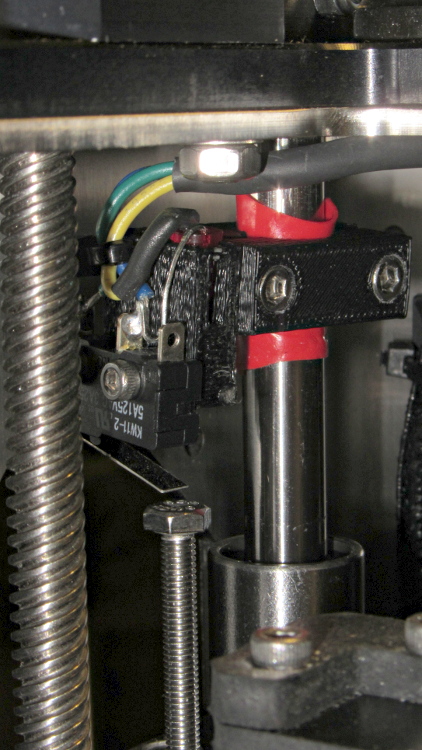
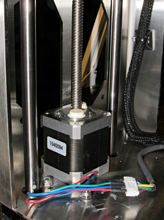
    So Line 7 disables the stepper motors. In an ideal world, the Z axis stage would then free-fall to the bottom of the chassis during the 4 second pause produced by the G4 S3 instruction. In the real world, that works most of the time, but the platform sometimes sticks where it is. You don’t want to home the Z axis to the top of its travel, because that will eventually crunch the nozzle into those clips, so I plan to add a bottom limit switch so I can drive the platform to a known location away from everything else.

    The default M2 Start G-Code puts the XY origin at the front left side of the platform, following the RepRap convention. Maybe it’s just me, but having the origin in the middle of the platform makes more sense for my objects; most of my OpenSCAD models are more-or-less symmetric, so putting the XY origin at their center works well. Ultimately, it doesn’t matter as long as you’re consistent, but my Start G-Code doesn’t produce the same results as the Makergear setup.

    Line 9 homes the X axis and Line 10 sets the coordinate to -95. The X axis home position is about 5 mm from the left edge of the glass plate, so the nozzle has about 195 mm of travel to the right edge of the 200 mm plate. The X=0 origin will be in the middle of the printable range, with -95 mm to the left limit (the home position) and +95 to the right edge; the nozzle can travel another 30 mm beyond the right edge to about +125. Line 11 puts the nozzle in the middle of its travel at X=0.

    Line 12 homes the Y axis and Line 13 sets the coordinate to -125. The Y axis home position is almost exactly on the front edge of the 250 mm glass plate, so the Y=0 origin is centered on the plate. The nozzle can travel an additional 10 mm off the rear edge of the plate. Note that you must position the nozzle somewhere on the X axis that avoids the bulldog clips; any of X=±95 or X=0 will work. Line 14 puts the nozzle in the middle of the plate at Y=0; it’s already at X=0, so the plate is now centered.

    Line 15 homes the Z axis. I’ve set the limit switch so that the home position leaves exactly 1.0 mm between the nozzle and the glass plate, which I find easier to measure than the Makergear suggestion of 0.1 mm. Of course, that’s because I have a Starret taper gauge in my tool cabinet. Use what you have, but use it consistently.

    Line 16 sets the Z axis coordinate position to +1.0 mm, matching the measured height, so that Z=0 corresponds to the nozzle exactly kissing the glass plate. The Makergear defaults put Z=0 about 0.1 mm above the platform; I’d rather apply model- and material-dependent offsets to “natural” machine positions.

    All of that ignores Z axis backlash. Some preliminary guesstimates put that around 0.1 mm, far better than my Sherline, but still large with respect to the layer thickness. I need more measurements of that, plus some measurements of the actual glass flatness. I think the glass bows upward by about 0.1 mm in the middle, but that requires better probing that will be easier under LinuxCNC control where I can do automated platform mapping.

    With the nozzle parked 1.0 mm over the platform, the next two lines wait for everything to reach the proper temperature. I preheat the platform and crank up the extruder temperature before starting the program , so these steps don’t take too long.

    However, the nozzle cools off as the drool contacts the much colder platform (it’s heated to 70 °C, but that’s cooler than 150-ish °C by a considerable margin) and the PID loop struggles to reheat it. I think that’s due to the default I term being only 0.1, which reduces integral windup during preheating, but also slows recovery from a sudden thermal load. It helps to preheat the nozzle about 10 °C over the desired temperature, then let it cool during this step.

    M2 - Wipe blobs on glass platform
    M2 – Wipe blobs on glass platform

    Line 19 uses Nophead’s trick (which I cannot find now) of planting the nozzle on the plate at Z=0.0 to reduce drool, although I do that after the nozzle reaches extruding temperature. The drool forms a blob on the platform as the nozzle heats, but the nozzle punches directly through it on the way to Z=0.0.

    Line 20 runs 10 mm of filament into the hot end to pressurize the extruder. Some of the molten goo oozes out around the nozzle, enlarging the blob on the glass plate. The object of the game is to leave all that behind: having a generous contact patch on the glass helps.

    The larger blob on the left of the picture (at Y=-125) comes from that process.

    Line 21 starts the wiping dance:

    • Raise the nozzle above the blob to Z=5 mm
    • Move away from the blob by 5 mm. I’ll probably change this to move in the +X direction.
    • Tap the nozzle on the platform, so (almost all of) the molten PLA slides away from the orifice
    • Get 0.1 mm of clearance from the platform, directly over the new blob
    • Scoot off to print a Skirt extrusion around the object

    The smaller, rather flat, blob on the right comes from the nozzle tap. A thin hair may stretch from the blob to the start of the skirt, but it doesn’t amount to much.

    Sometimes, of course, the blobs don’t adhere to the glass plate and accompany the nozzle to the start of the skirt. By the conservation of perversity, that’s also when the skirt starts on the far side of the origin, so the blob smears all over the object’s first layers. The Makergear wipe process extrudes the waste filament over the side of the plate, then shears it off as the nozzle returns to the surface; I’ll try blending that in with my startup sequence at some point.

    My slic3r configuration extrudes at least 15 mm of filament into the skirt, giving the extruder plenty of time to reach a steady state before starting the actual object. Generally that’s far more than enough filament, but sometimes … well, it’s a good idea to watch what’s going on.

    On the other end of the printing process, the End G-Code routine handles shutdown with the object on the platform:

    ;-- Slic3r End G-Code for M2 starts --
    ;  Ed Nisley KE4NZU - March 2013
    M104 S0		; drop extruder temperature
    M140 S0		; drop bed temperature
    M106 S0		; bed fan off
    G1 Z195	F2500	; lower bed
    G1 X0 Y0 F30000	; center nozzle
    M84     	; disable motors
    ;-- Slic3r End G-Code ends --
    

    Line 3 begins turning the heaters and bed fan off. I’ve unplugged the fan for now, so Line 5 is just for completeness.

    Line 6 lowers the bed to the bottom under power, because that’s faster that a free fall and it’s guaranteed to work.

    With the object safely out of the way, Line 7 centers the nozzle over the platform.

    Finally, Line 8 turns off the steppers off; the platform drops another few millimeters

    Then everything cools down. Because I run the platform at well above PLA’s glass transition temperature, it must cool for quite a while until the object stiffens up.

  • Makergear M2: Slic3r Configuration

    What you see here represents a stake in the ground, rather than the be-all and end-all configuration. Remember that my intent is to get the M2 working with its more-or-less stock hardware and firmware, make some straightforward improvements, then transition to LinuxCNC for better control and measurement.

    While printing a variety of test objects (which I’ll describe shortly), I casually permuted the temperatures, speeds, and timings to gradually improve the results. In nearly all cases, the M2 performs much better than my old and highly modified Thing-O-Matic ever did, so the machinery lives up to its reputation.

    Slic3r seems to be nearly as good at slicing as Skeinforge 50 and much faster, although it doesn’t handle very thin walls quite right and produces bizarre speed glitches on (or near?) layers with bridges. I wasn’t taking notes during any of this, which means you should regard it as hearsay evidence at best, but, on the whole, slic3r seems to work just fine for the non-pathological objects I generally build.

    This is the Slic3r config.ini file, which (I think) contains all of the configuration information now distributed throughout the smaller files controlled by slic3r.ini:

    # generated by Slic3r 0.9.8 on Tue Apr  9 08:43:22 2013
    bed_size = 190,250
    bed_temperature = 70
    bottom_solid_layers = 3
    bridge_fan_speed = 100
    bridge_flow_ratio = 1
    bridge_speed = 100
    brim_width = 0
    complete_objects = 0
    cooling = 1
    default_acceleration = 0
    disable_fan_first_layers = 3
    duplicate = 1
    duplicate_distance = 6
    duplicate_grid = 1,1
    end_gcode = ;-- Slic3r End G-Code for M2 starts --\n;  Ed Nisley KE4NZU - March 2013\nM104 S0        ; drop extruder tempeature\nM140 S0        ; drop bed temperature\nM106 S0        ; bed fan off\nG1 Z195    F2500    ; lower bed\nG1 X0 Y0 F30000    ; center nozzle\nM84         ; disable motors\n;-- Slic3r End G-Code ends --
    external_perimeter_speed = 75
    extra_perimeters = 1
    extruder_clearance_height = 20
    extruder_clearance_radius = 20
    extruder_offset = 0x0
    extrusion_axis = E
    extrusion_multiplier = 0.9
    extrusion_width = 0.40
    fan_always_on = 0
    fan_below_layer_time = 30
    filament_diameter = 1.70
    fill_angle = 45
    fill_density = 0.10
    fill_pattern = honeycomb
    first_layer_bed_temperature = 70
    first_layer_extrusion_width = 0
    first_layer_height = 100%
    first_layer_speed = 30
    first_layer_temperature = 165
    g0 = 0
    gap_fill_speed = 100
    gcode_arcs = 0
    gcode_comments = 0
    gcode_flavor = reprap
    infill_acceleration = 0
    infill_every_layers = 1
    infill_extruder = 1
    infill_extrusion_width = 0
    infill_speed = 200
    layer_gcode =
    layer_height = 0.25
    max_fan_speed = 100
    min_fan_speed = 50
    min_print_speed = 20
    min_skirt_length = 15
    notes =
    nozzle_diameter = 0.35
    only_retract_when_crossing_perimeters =
    output_filename_format = [input_filename_base].gcode
    perimeter_acceleration = 0
    perimeter_extruder = 1
    perimeter_extrusion_width = 0
    perimeter_speed = 100
    perimeters = 1
    post_process =
    print_center = 0,0
    randomize_start = 1
    retract_before_travel = 1
    retract_length = 1.0
    retract_length_toolchange = 5
    retract_lift = 0
    retract_restart_extra = 0
    retract_restart_extra_toolchange = 0
    retract_speed = 300
    rotate = 0
    scale = 1
    skirt_distance = 5
    skirt_height = 1
    skirts = 1
    slowdown_below_layer_time = 10
    small_perimeter_speed = 25
    solid_fill_pattern = concentric
    solid_infill_below_area = 70
    solid_infill_every_layers = 0
    solid_infill_speed = 100
    start_gcode = ;-- Slic3r Start G-Code for M2 starts --\n;  Ed Nisley KE4NZU - March 2013\nM140 S[first_layer_bed_temperature]    ; start bed heating\nG90                ; absolute coordinates\nG21                ; millimeters\nM83                ; relative extrusion distance\nM84                ; disable stepper current\nG4 S3            ; allow Z stage to freefall to the floor\nG28 X0            ; home X\nG92 X-95        ; set origin to 0 = center of plate\nG1 X0 F30000    ; origin = clear clamps on Y\nG28 Y0            ; home Y\nG92 Y-125         ; set origin to 0 = center of plate\nG1 Y-122 F30000    ; set up for prime near front edge\nG28 Z0            ; home Z\nG92 Z1.0            ; set origin to measured z offset\nM190 S[first_layer_bed_temperature]    ; wait for bed to finish heating\nM109 S[first_layer_temperature]    ; set extruder temperature and wait\nG1 Z0.0 F2500    ; plug extruder on plate\nG1 E10 F300        ; prime to get pressure\nG1 Z5 F2500        ; rise above blob\nG1 Y-115 F30000    ; move away\nG1 Z0.0 F2500    ; dab nozzle to remove outer snot\nG4 P1            ; pause to clear\nG1 Z0.1            ; clear bed for travel\n;-- Slic3r Start G-Code ends --
    support_material = 0
    support_material_angle = 0
    support_material_extruder = 1
    support_material_extrusion_width = 0
    support_material_pattern = rectilinear
    support_material_spacing = 2.5
    support_material_speed = 100
    support_material_threshold = 0
    temperature = 165
    threads = 2
    toolchange_gcode =
    top_solid_infill_speed = 50
    top_solid_layers = 3
    travel_speed = 500
    use_relative_e_distances = 0
    vibration_limit = 0
    z_offset = 0
    
  • Makergear M2: Marlin Configuration Tweaks

    The slightly customized version of Marlin shipped with the M2 works well enough, but some of the constants required adjustment.

    Most of the changes appear in the Configuration.h file…

    Start by tweaking the version info so you know what’s in the Flash ROM every time it starts up:

    #define STRING_VERSION_CONFIG_H "2013-03-27" //Personal revision number for changes to THIS file.
    #define STRING_CONFIG_H_AUTHOR "Ed Nisley - KE4ZNU" //Who made the changes.
    

    I reduced the maximum temperatures to match the Makergear-defined limits, even though those are far beyond what I expect to use. I’ll probably cut them back even further, but they’ll do for now:

    // When temperature exceeds max temp, your heater will be switched off.
    // This feature exists to protect your hotend from overheating accidentally, but *NOT* from thermistor short/failure!
    // You should use MINTEMP for thermistor short/failure protection.
    // Ed Nisley KE4ZNU - 26 March 2013 - reduce to M2 limit
    #define HEATER_0_MAXTEMP 230
    #define HEATER_1_MAXTEMP 230
    #define HEATER_2_MAXTEMP 230
    #define BED_MAXTEMP 125
    

    Long ago, I settled on a much lower extrusion temperature for ABS in the Thing-O-Matic than nearly everyone else and that’s also holding true for PLA in the M2, so I reduced the minimum allowable temperature limit from 170 °C to 120 °C. The firmware seems to use a “less-than-or-equal” test, so it prevents extrusion at exactly 120 °C. Close enough:

    // M2 - reduce to allow much cooler PLA extrusion
    // KE4ZNU - 24 March 2013
    //#define EXTRUDE_MINTEMP 170
    #define EXTRUDE_MINTEMP 120
    

    Before I added the shim around the Z axis leadscrew bearing, the default homing speed excited a howling mechanical resonance. Increasing the homing speed moved the vibration away from the resonance, but the real cure was to reduce the motor current, which eliminated the four dead spots per full step:

    // KE4ZNU - 24 March 2013 - M2 - Goose Z feedrate to avoid resonance
    //#define HOMING_FEEDRATE {50*60, 50*60, 4*60, 0}  // set the homing speeds (mm/min)
    #define HOMING_FEEDRATE {50*60, 50*60, 6*60, 0}  // set the homing speeds (mm/min)
    

    Dan Newman’s comments to the post about the Z axis performance calculations suggest some rationalization should happen among all the maximum speed and acceleration settings; they appear to be quite inconsistent right now. This will take a bit of measurement, but I think substantive measurements & changes must wait until I get the LinuxCNC controller running.

    The block of constants for the motor currents includes some misleading comments. I added the RAMBo design equations, which will become invalid when a board iteration changes either the supply voltage or the sense resistor value, and a bit of explanatory text.

    The extruder current seemed slightly low, as it would skip steps while infilling large bottom layers. This happened before I lowered the extruder temperature, so the nominal value may be right on the edge of goodness. The new value of 1.5 A heats the motor to about 120 °C, which is higher than I’d like for something attached to a plastic mount, but I anticipate some changes there in the near future.

    I increased the XY motor currents to 1.5 A in anticipation of using higher speeds, although that wasn’t based on any evidence. The motors now run at about 120 °C, which is OK because they’re attached to solid metal parts (albeit without heatsink compound).

    As described earlier, reducing the Z motor current to 0.6 A from 1.1 A didn’t materially affect the maximum torque, dramatically smoothed the motion, and slightly reduced the temperature. It still runs at nearly 130 °C, despite heatsinking to the chassis, and is in line for replacement.

    // Motor Current setting (Only functional when motor current pins are connected to digipot)
    // Values 0-255
    // RAMBO 135 = ~0.75A, 185 = ~1A
    // Ed Nisley KE4ZNU - 25 March 2013 - increase XY current to 1.5 A (185 was 135)
    //		decrease Z current to nominal 600 mA (75 was 135) based on 19 V / 28 ohm winding
    //		value = 255 * (0.8 * Imax) / 1.66 V
    // Ed Nisley KE4ZNU - 27 March 2013 - increase E current to 1.5 A (185 was 165)
    //		to support 300 mm/s XY extrusion speed
    #define DIGIPOT_MOTOR_CURRENT
    #define X_CURRENT 185
    #define Y_CURRENT 185
    #define Z_CURRENT 75
    #define E0_CURRENT 185 //For MakerGear M2, 165 is a good starting point
    #define E1_CURRENT 125
    

    The only change to Configuration_adv.h increases the stepper timeout to allow the build platform to reach operating temperature; the default value shut off the motors just before printing started. The value obviously depends on the start and end temperatures, so more testing is in order:

    //default stepper release if idle
    // Ed Nisley KE4ZNU - 25 March 2013 - make deactivate timeout exceed plate heating time
    #define DEFAULT_STEPPER_DEACTIVE_TIME 400