Ed Nisley's Blog: Shop notes, electronics, firmware, machinery, 3D printing, laser cuttery, and curiosities. Contents: 100% human thinking, 0% AI slop.
Tag: Improvements
Making the world a better place, one piece at a time
That comment suggested a different solution to the problem of having the display manager start before the NFS mounts complete. When that happens, you can sign in and start programs that won’t have access to their data, producing all manner of heartache and confusion.
One complication: it seems /etc/rc.local starts and runs before the network (among other tidbits) gets connected and becomes ready, which means you can’t just plunk your code in that file like you used to, at least not in Ubuntu. Fixing that requires an upstart script triggered when the network interface finally hauls itself to its feet.
There’s no actual link between the NFS mount commands and the display manager startup, but it seems that if you don’t attempt to mount the NFS shares before the network becomes active (which is what happen with shares automounted through /etc/fstab), but wait for the network to come up and then issue the mounts, the shares mount almost instantly and become ready by the time the display manager presents the login screen. That’s better than the kludge I had figured out and works fine, so I’ll run with it until something else breaks.
The not-quite-deterministic fix has three parts:
Use noauto in the fstab entries for the NFS shares
Create an upstart script to mount those shares after eth0 lights up
Allow lightdm to start up normally (i.e., remove my hackish attempts)
A sample line from fstab, with the vital noauto option:
The /etc/init/local.conf script assumes the network interface will be eth0, which does not generalize to wireless networks on laptops and suchlike. You could add some Boolean logic to wait for the first of several interfaces, I suppose:
description "Stuff that should be in /etc/rc.local"
author "Ed Nisley - KE4ZNU"

start on (local-filesystems and net-device-up IFACE=eth0)
stop on shutdown
script

logger Starting local init...

logger Mounting NFS filesystems
mount /mnt/bulkdata
mount /mnt/userfiles
mount /mnt/diskimages
mount /mnt/music

logger Ending local init

end script
The lightdm.conf file reverts to the distribution version, with this starting trigger:
start on ((filesystem
           and runlevel [!06]
           and started dbus
           and (drm-device-added card0 PRIMARY_DEVICE_FOR_DISPLAY=1
                or stopped udev-fallback-graphics))
          or runlevel PREVLEVEL=S)
It’s worth noting that the upstart interpreter hates comment lines embedded within statements: it does not regard them as whitespace and does not ignore them. Just don’t do it. That explains some of the problems I encountered before, but fixing those problems did not eliminate the overall issue.
The end result of all that hocus-pocus makes the box boot the way it used to: the display manager comes up promptly, presents the GUI login screen, and the NFS mounts are ready when you are.
More hal-config.lbr tweakage produced enough HAL blocks to completely define the Sherline CNC mill’s HAL connections, all wired up in a multi-page schematic (Eagle-LinuxCNC-Sherline.zip.odt) that completely replaces all the disparate *.hal files I’d been using, plus a new iteration of the hal-write-2.5.ulp Eagle-to-HAL conversion script.
The first sheet (clicky for more dots) defines the manually configured userspace and realtime modules:
Sherline Schematic – 1
That sheet has three types of Eagle devices:
Generalized LoadRT – devices like trivkins that require only a loadrt line
Dedicated LoadRT – devices like motion that require functions connected to a realtime thread
Generalized LoadUsr – devices like hal_input with a HAL device, but no function pins
The device’s NAME field contains either the module name (for the specialized devices with functions) or a generic MODULE for everything else, preceded by an optional index that imposes an ordering on the output lines. The device’s VALUE field contains the text that will become the loadrt or loadusr line in the HAL file. Trailing underscores act as separators, but are discarded by the conversion script.
The immensely long line is the VALUE field that plugs a bunch of variables from the Sherline.ini file into the motion controller.
The conversion script doesn’t do anything special for those devices, other than transfer the VALUE field to the HAL file. Ordinary HAL devices, the ones with functions that don’t require any special setup, must appear in the conversion script’s list of device names, so that it can recognize them and deal with their connections.
Next, the parallel port configuration, which uses the D525’s system board hardware:
Sherline Schematic – 2
The stepconf configuration utility buries the parallel port configuration values in the default HAL file as magic numbers. I moved them to a new stanza in the INI file, although the syntax may not be robust enough to support multiple cards, ports, and configurations. This, however, works for now:
That LOGIC block is new and serves as an AND gate that produces a combined enable signal for the parallel port. The stepconf utility uses the X axis enable signal, but, seeing as how the Sherline controller doesn’t use the result, none of that matters on my system.
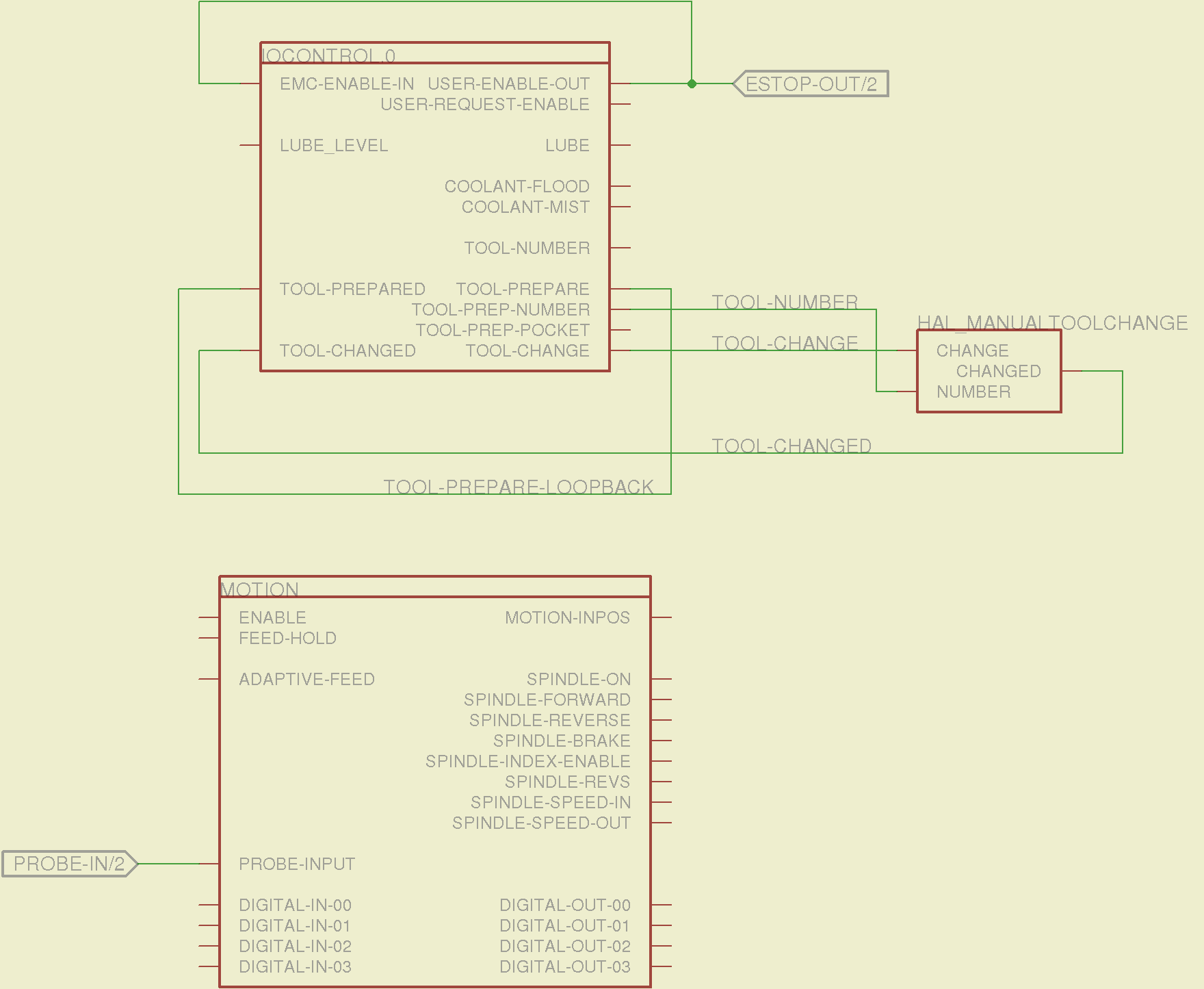
The tool height probe and manual tool change wiring:
Sherline Schematic – 3
I’m not convinced the Emergency Stop polarity is correct, but it matches what was in the original HAL file. As before, the Sherline driver box ignores that output, so none of that matters right now.
Four very similar pages define the XYZA step-and-direction generators. This is the X axis driver:
Sherline Schematic – 4
You can imagine what the next three pages for the YZA logic look like, right? There are also a few blank pages in the schematic, so the numbers jump abruptly.
The magic part of this is having Eagle manage all the tedious renumbering and counting. If you remember to adjust the name of the first module from, say, AXIS.1 to AXIS.0, then the rest get the proper numbers as you go along.
The remainder of the schematic implements the Joggy Thing’s logic, much as described there. I discovered, quite the hard way, that copy-and-pasting an entire schematic from elsewhere does horrible things to the device numbering, but I’m not sure how to combine two schematics to limit the damage. In any event, manually adjusting a few pages wasn’t the worst thing I’ve ever had to do; starting with a unified schematic should eliminate that task in the future.
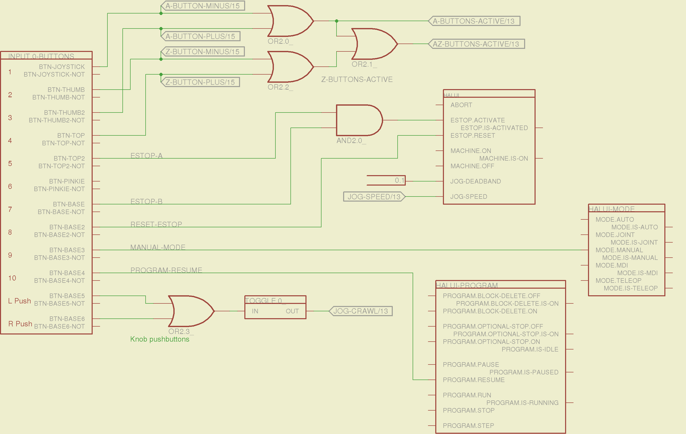
The miscellaneous buttons:
Sherline Schematic – 11
The joystick and hat values:
Sherline Schematic – 12
The joystick deadband logic now uses the (new with HAL 2.5, I think) input.n.abs-x-flat pins, which eliminated a tangle of window comparator logic.
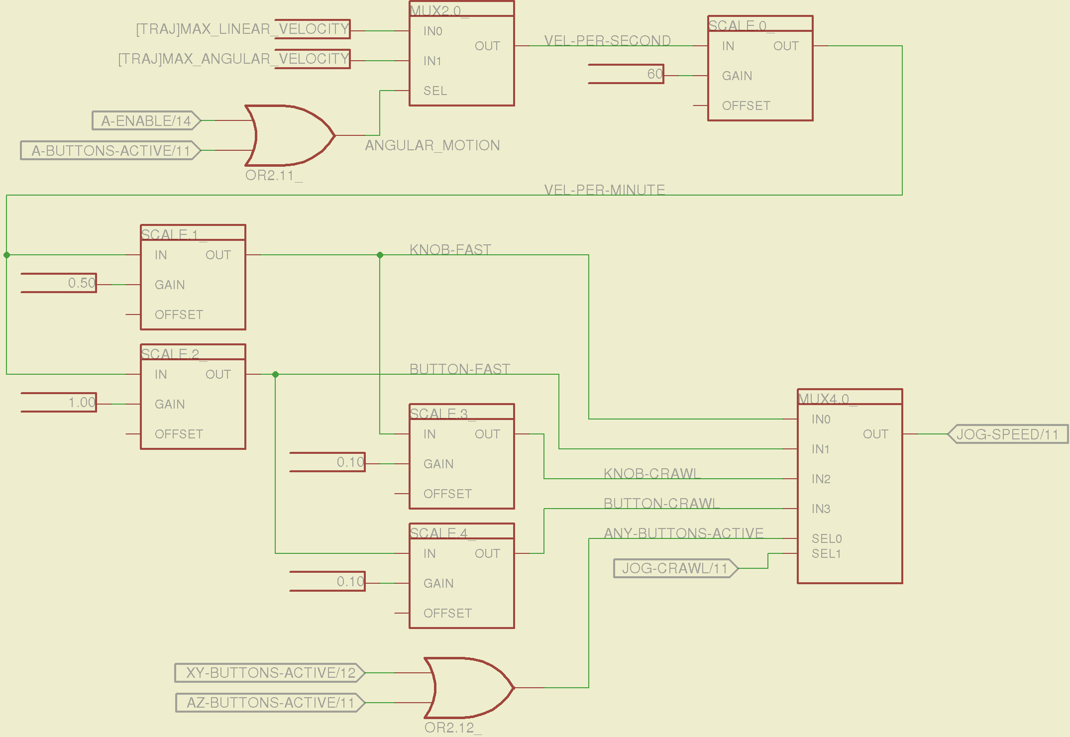
The jog speed adjustment logic that sets the fast and crawl speeds:
Sherline Schematic – 13
I should probably put the speed ratios in the INI file, but that’s in the nature of fine tuning.
The lockout logic that remembers which axis started moving first on a given joystick and locks out the other axis, which greatly simplifies jogging up to an edge without bashing into something else:
Sherline Schematic – 14
Combine all those signals into values that actually tell HAL to jog the axes:
Sherline Schematic – 15
The last page connects all the realtime function pins to the appropriate threads:
Sherline Schematic – 16
The LinuxCNC documentation diverges slightly from the implementation, but a few iterations resolved all the conflicts and had the additional benefit that I had to carefully think through what was actually going on.
A deep and sincere tip o’ the cycling helmet to the folks making LinuxCNC happen!
Although the Sherline mill doesn’t have more than a few minutes of power-on time with the new HAL file, the Joggy Thing behaves as it used to and the axes move correctly, so I think the schematic came out pretty close to the original HAL file.
The next step: draw a new schematic to bring up and exercise a different set of steppers…
To that end, here’s a checklist for creating a new Eagle device corresponding to a HAL module.
Remember: although this process has a tremendous number of moving parts, you do it exactly once when you need a device that doesn’t already exist. After that, you just click to add an existing device to your schematic, wire it up, then the tedious write-only HAL overhead happens automagically.
Cross-check the documentation with the actual component code!
The man page lists the names, pins, parameters, and suchlike, but may have typos. This isn’t a criticism, it’s a fact of life.
Before investing a ton o’ time creating an Eagle device, load the module and find out what’s really there:
halrun
halcmd: loadrt conv_float_s32
halcmd: show all
Loaded HAL Components:
ID      Type  Name                                      PID   State
     4  RT    conv_float_s32                                  ready
     3  User  halcmd2395                                 2395 ready

Component Pins:
Owner   Type  Dir         Value  Name
     4  float IN              0  conv-float-s32.0.in
     4  s32   OUT             0  conv-float-s32.0.out
     4  bit   OUT         FALSE  conv-float-s32.0.out-of-range

... snippage ...

Parameters:
Owner   Type  Dir         Value  Name
     4  bit   RW          FALSE  conv-float-s32.0.clamp
     4  s32   RO              0  conv-float-s32.0.time
     4  s32   RW              0  conv-float-s32.0.tmax

... snippage ...

Exported Functions:
Owner   CodeAddr  Arg       FP   Users  Name
 00004  fc0a9000  fc0630b8  YES      0   conv-float-s32.0
... snippage ...
Achtung!
The module name uses underscores as separators: loadrt conv_float_s32
The function name uses h-y-p-h-e-n-s as separators: conv-float-s32.0
Unlike in the Linux kernel, the two characters are not equivalent
Add the HAL Module to the Conversion Script
The hal-write.ulp script contains a table of all the module names, so you must update the script in parallel with the hal-config.lbr Eagle library.
However, you can create an Eagle device that is not a HAL module by omitting it from the script. In that case, the Eagle device name will become part of the net names that define and interconnect the pins, but the script will not create a statement to load a module. For example, the hal_input userspace program creates a set of pins for each input device that start with input.n, but there’s no corresponding HAL module. I’ll put up an example of all this in a bit.
Create a Schematic Symbol
The name of the symbol is not critical: CONVERT.sym
use either dashes or hyphens as you prefer
The >NAME string must be on layer 95-Names
No need for a >VALUE string, but put it on layer 96-Values if present
HAL pins become symbol pins
Use the HAL pin name, with hyphens
Set Visibility to Pin
Set Direction to in / out / io to match the HAL description
Set Function to None to indicate an ordinary net connection
Verify the pins against the HAL device!
Create a HAL Schematic Device
The new device name must match the HAL module name, with underscores, as entered in the conversion script table
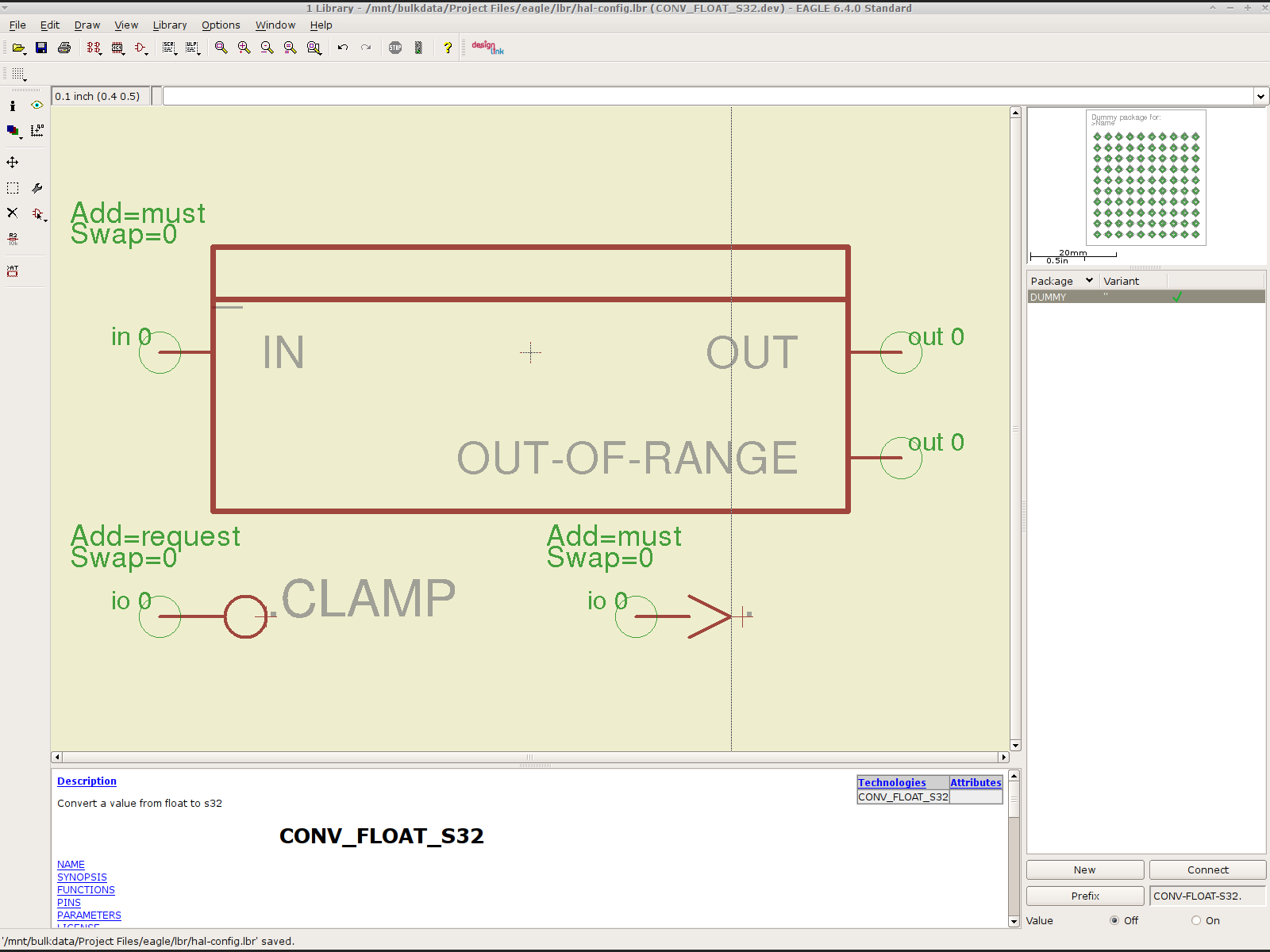
CONV_FLOAT_S32.dev
Set the Prefix to the HAL function name, plus a trailing period, with hyphens
CONV-FLOAT-S32.
Create the Description using copy-and-paste from the HTML source: use the man page in the LinuxCNC doc
Ctrl-U in Firefox reveals the HTML source, Ctrl-A and Ctrl-C, flip windows, then Ctrl-V
Delete all the boilerplate at the top, leave the centered Title, ditch the reference links
Add the symbol you created earlier or reuse an existing symbol
Set the symbol NAME to a single underscore: _
Change the Add level to must
Add a PIN_FUNCTION symbol to the device
Change the symbol name from G$1 (or whatever) to a single period: .
Change the Add Level to must
Add PIN_PARAMETER symbols as needed
Change the symbol name from G$1 (or whatever) to the parameter name preceded by a single period: .CLAMP
Change the Add Level to request
Change the Direction as needed
Add the DUMMY physical package, then connect all the pins to pads
Create a non-HAL Schematic Device
The new device name may be anything that’s not in the conversion script table
The Prefix must match the desired pin names, plus a trailing period. For hal_input pins:
INPUT.
Create the Description as above
Add the symbol you created earlier
Set the symbol NAME to a single underscore: _
Change the Add level to must
Do not add a PIN_FUNCTION symbol, because it has no corresponding module
Add PIN_PARAMETER symbols as needed
Change the symbol name from G$1 (or whatever) to the parameter name preceded by a single period: .CLAMP
Change the Add Level to request
Change the Direction as needed
Add the DUMMY physical package, then connect all the pins to pads
Devices may have multiple Symbols, with different Add Level options; can seems appropriate. As nearly as I can tell, you must name each Symbol as a suffix to the full name to differentiate them within the Device; I use a hyphen before the suffix, so that -KEYS generates INPUT.0-KEYS. Those suffixes don’t appear elsewhere in the generated HAL configuration file.
Save the library, update it in the schematic editor (Library → Update ...), and you’re set.
Although it’s tempting, do not include a version number in the library file name, because Eagle stores the file name inside the schematic file along with the devices from that file. As a result, when you bump the library version number and use devices from the new library file, the schematic depends on both library files and there’s no way within Eagle to migrate devices from one library to the other; you must delete the existing devices from the schematic and re-place them from the new library. Or you can do like I did: hand-edit the XML fields inside the library file.
Eagle HAL Device
You’ll almost certainly drive this procedure off the rails, so let me know what I’ve screwed up. It does, in fact, work wonderfully well and, as far as I’m concerned, makes HAL usable, if only because HAL is a write-only language to start with and now you need not read it to modify it.
As nearly as I can tell, Epson designed a number of features into the R380 specifically to thwart CISS installation, including the awkward bridge across the middle of the printer that interferes with the flat tube feeding ink to the flying cartridges. I managed to route the previous CISS tubing around the bridge, but this time I figured enough was enough.
So I tucked a shop rag inside the printer, put a vacuum cleaner nozzle near the operation, and applied a fine-tooth pull saw to the bridge:
Epson R380 – bridge removed
That certainly simplified the rest of the installation…
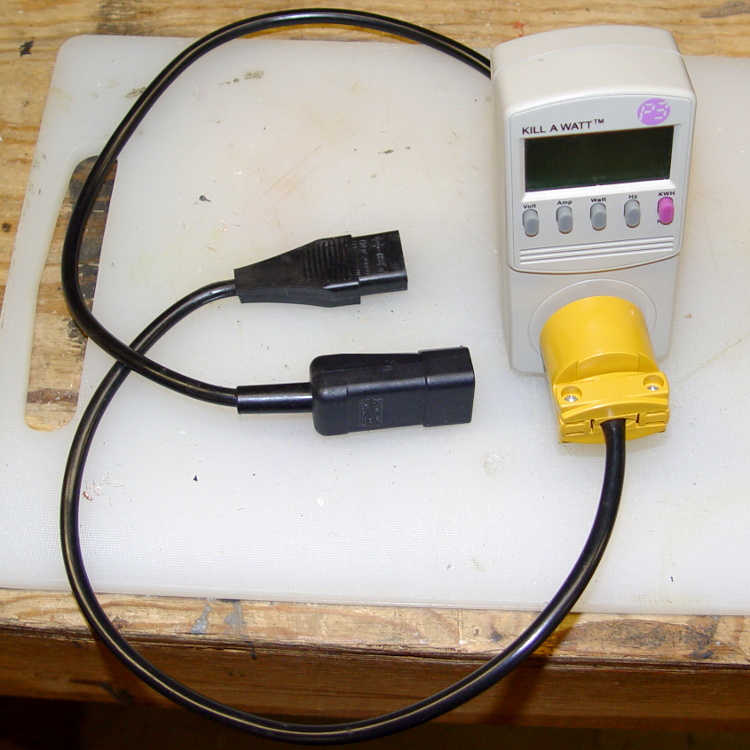
It makes measuring PC power consumption much easier!
I picked up some cheap AC plugs and sockets, cut a short IEC extender cable in half, and wired ’em up. If the IEC extender link breaks again, search amazon.com for something like “computer power cord extension” and rummage around.
US NEMA 5 plug / socket hint: the blade marked W is neutral. More expensive hardware will have dark brass = hot, light brass = neutral, but don’t bet your life on it.
I bought an off-lease Optiplex 780 in the Small Form Factor (SFF) version to replace my ancient Pentium D; it’s also available in Small Desktop Tower (SDT) and Ultra-SFF variations. The SFF box has two PCI slots and one PCI-E slot, which let me install a half-height dual-output video card, with results described yesterday. I innocently believed the PCI-E slot would have enough clearance for the video card, what with these things being standardized and all.
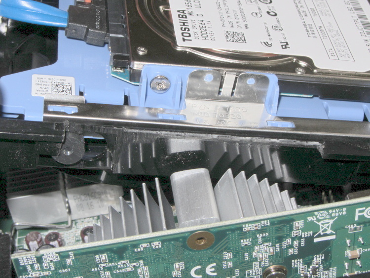
Turns out that the heatsink collided with a flange on the hard drive carrier, with about 5 mm of overlap. Fortunately, the bracket is plastic and I have no qualms about chopping up the hardware. A few minutes of Quality Shop Time removed a section of the offending flange and gave the video card just enough clearance:
Optiplex 780 SFF drive bracket
The heatsink reflects in the shiny surface of the carrier, with the scar from the missing flange just above that. The small dark-gray disk on the far left is a grommet holding a pin that supports the drive; it installs through the larger circular opening and snaps leftward.
You must install the video card and then snap the drive carrier into place. The heatsink protrudes above the flange, with the left side just barely clearing that grommet.
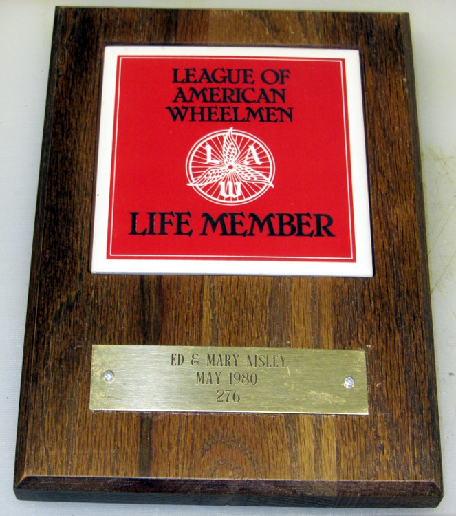
The brass plate from this plaque rattled down the basement stairs(*) a while ago:
League of American Wheelmen plaque
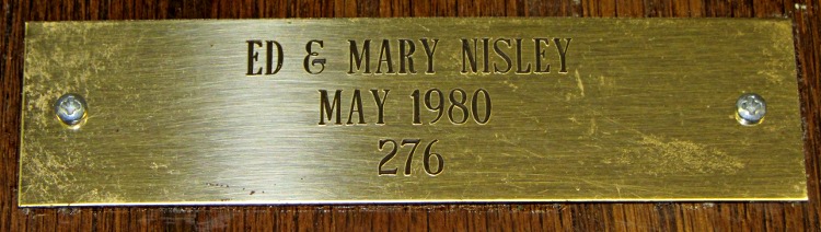
As you might expect, the adhesive failed and has been replaced at least once. This time, I drilled a pair of 2-56 clearance holes in the plate, match-marked the wood with a punch, drilled a pair of tapping holes, and put it all back together.
There’s not much to see, but I’m pretty sure that plate won’t fall off ever again:
League of American Wheelmen plaque – detail
The lacquer finish has begun disintegrating, but I wasn’t in the mood to strip-and-restore that. The tile remains firmly affixed; when that falls out, it won’t be pretty.
The LAW long ago morphed into the League of American Bicyclists, after deeming Wheelmen as too gender-specific for the modern era.
(*) We hang plaques, certificates, diplomas, and suchlike on the walls beside the basement stairs. Every time we pass by, it’s an Ego Trip…