Given that I’m throwing all the balls in the air at once:
- V4 hot end / filament drive
- 24 VDC motor / logic power supply
- PETG filament
It seemed reasonable to start with the current Marlin firmware, rather than the MakerGear version from long ago. After all, when you file a bug report, the first question is whether it happens with the Latest Version.
Marlin has undergone a Great Refactoring that moved many of the constants around. I suppose I should set up a whole new Github repository, but there aren’t that many changes and I’ve gotten over my enthusiasm for forking projects.
Anyhow, just clone the Marlin repo and dig in.
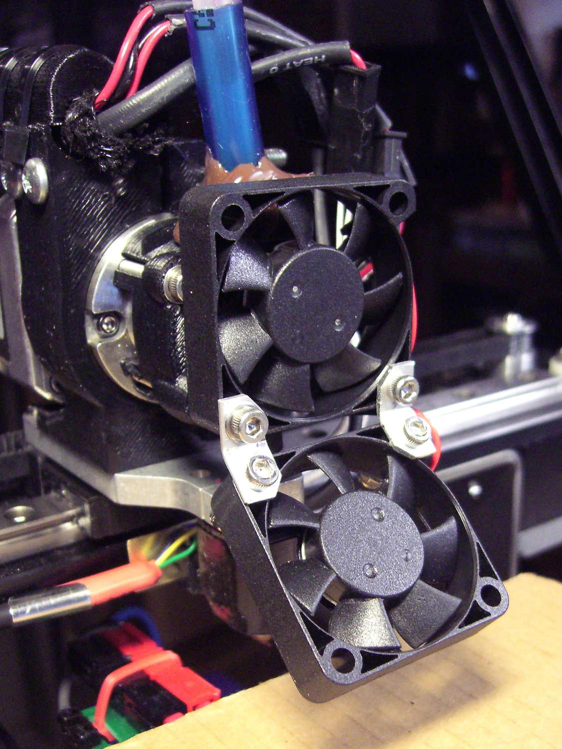
In Marlin_main.cpp, turn on the Fan 1 output on Arduino pin 6 that drives the fans on the extruder and electronics box:
pinMode(6,OUTPUT);	// kickstart Makergear M2 extruder fan
digitalWrite(6,HIGH);
You could use the built-in extruder fan feature that turns on when the extruder temperature exceeds a specific limit. I may try that after everything else works; as it stands, this shows when the firmware gets up & running after a reset.
In Configuration_adv.h, lengthen the motor-off time and set the motor currents:
#define DEFAULT_STEPPER_DEACTIVE_TIME 600
#define DIGIPOT_MOTOR_CURRENT {185,215,185,185,135}
The Configuration.h file still has most of the tweaks:
#define STRING_CONFIG_H_AUTHOR "(Ed Nisley - KE4ZNU - Hotrod M2)"
#define STRING_SPLASH_LINE2 STRING_VERSION_CONFIG_H

#define BAUDRATE 115200

#define MOTHERBOARD BOARD_RAMBO

#define TEMP_SENSOR_0 1
#define TEMP_SENSOR_BED 1

#define HEATER_0_MAXTEMP 290
#define HEATER_1_MAXTEMP 290
#define HEATER_2_MAXTEMP 290
#define HEATER_3_MAXTEMP 290

#define X_MAX_POS 136
#define X_MIN_POS -100
#define Y_MAX_POS 125
#define Y_MIN_POS -127
#define Z_MAX_POS 175
#define Z_MIN_POS 0

#define HOMING_FEEDRATE {75*60, 75*60, 30*60, 0}

#define DEFAULT_AXIS_STEPS_PER_UNIT   {88.88,88.88,400,424.4}
#define DEFAULT_MAX_FEEDRATE          {450, 450, 100, 94}
#define DEFAULT_MAX_ACCELERATION      {5000,2500,2000,10000}

#define DEFAULT_ACCELERATION          10000
#define DEFAULT_RETRACT_ACCELERATION  10000
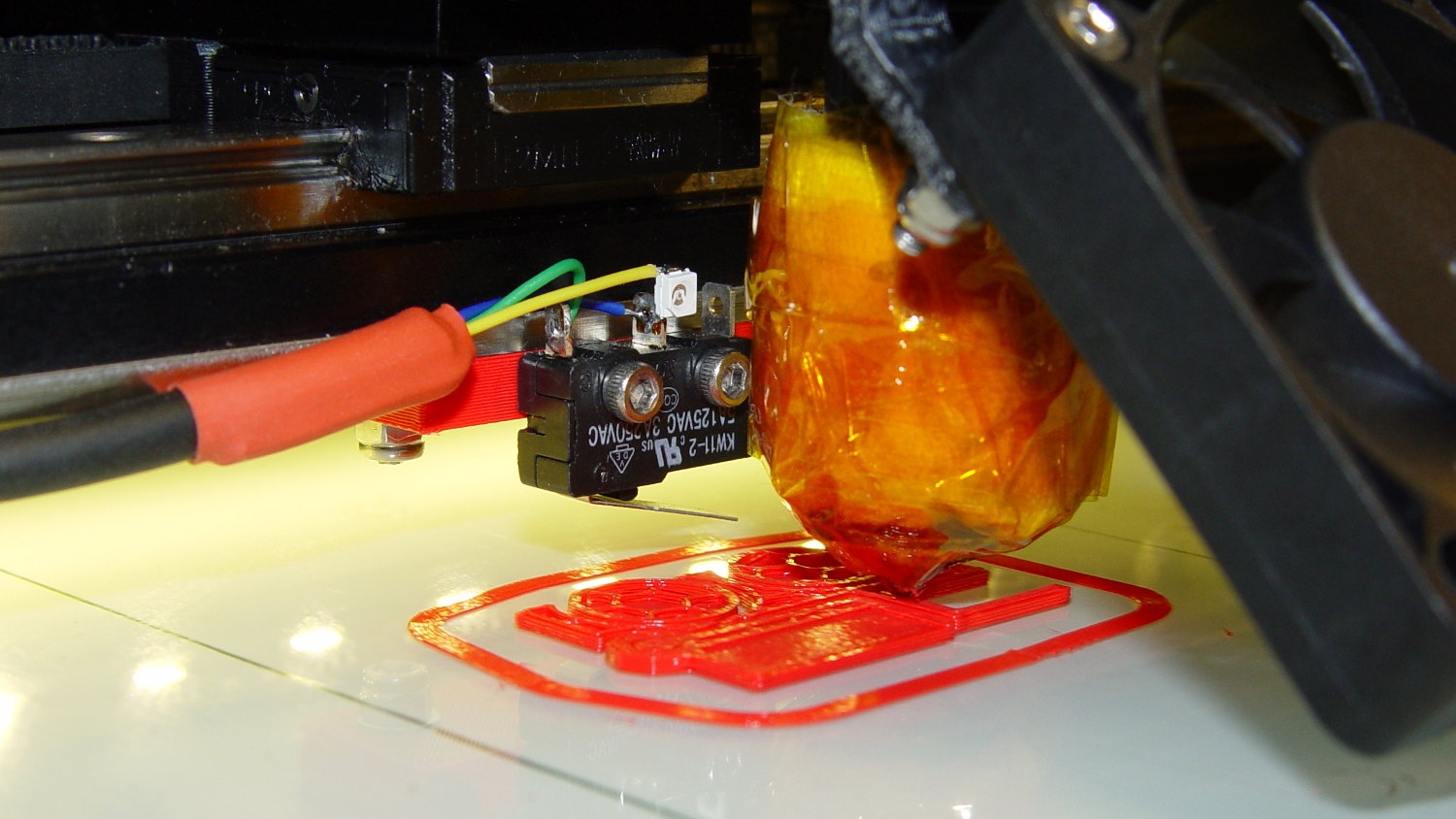
I missed the max & min position settings on the first pass (they’re new!), which matter because I put the origin in the middle of the platform, rather than the front-left corner. Marlin now clips coordinates outside that region, so the first thinwall calibration box only had lines in Quadrant 1…