Ed Nisley's Blog: Shop notes, electronics, firmware, machinery, 3D printing, laser cuttery, and curiosities. Contents: 100% human thinking, 0% AI slop.
Tag: Improvements
Making the world a better place, one piece at a time
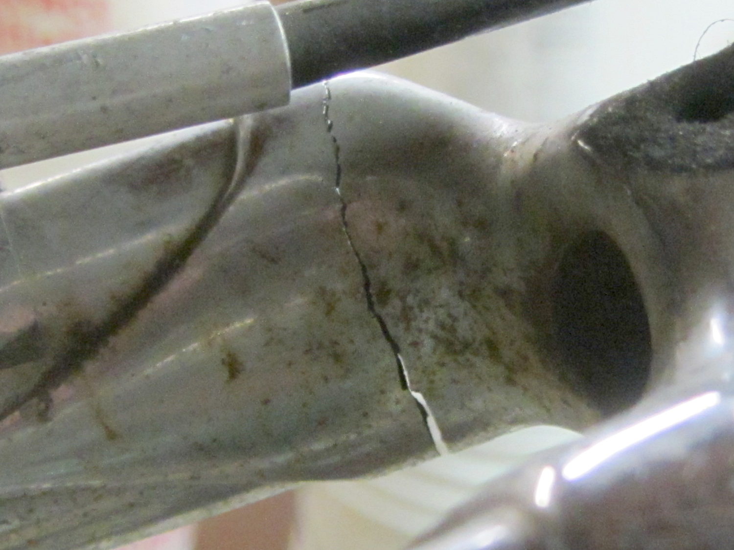
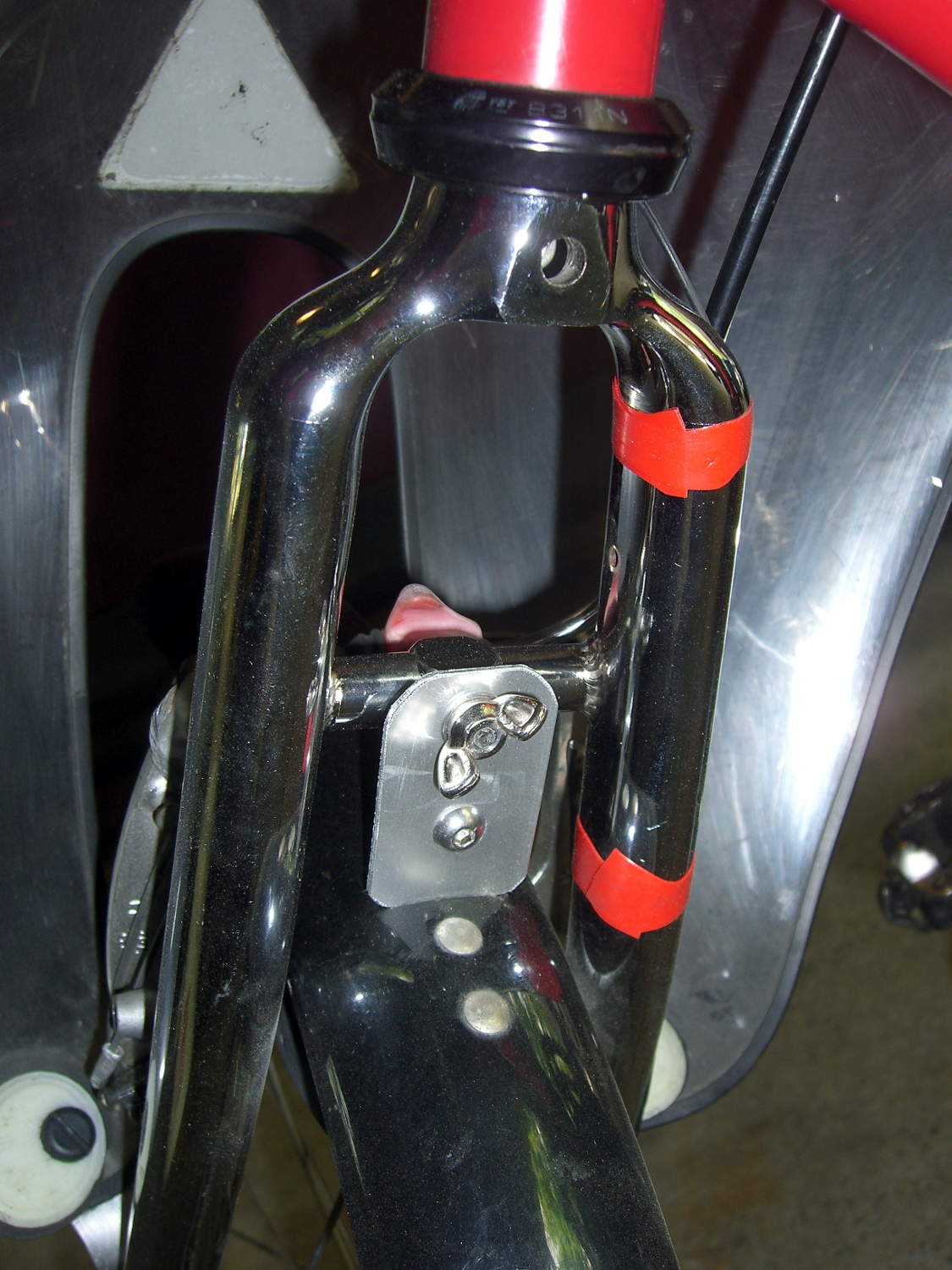
A view from the wheel side shows the crack in my Tour Easy’s fork lug had opened a bit more to the rear, which is about what you’d expect from the forces involved:
Tour Easy – cracked fork lug
Removing the handlebar stem from the fork steerer tube requires removing the fairing, its mounting brackets, the fender, a speed sensor, then snipping cable ties to release all the cables and wires. Minus the prep work, removing the fork from the bike isn’t anything special.
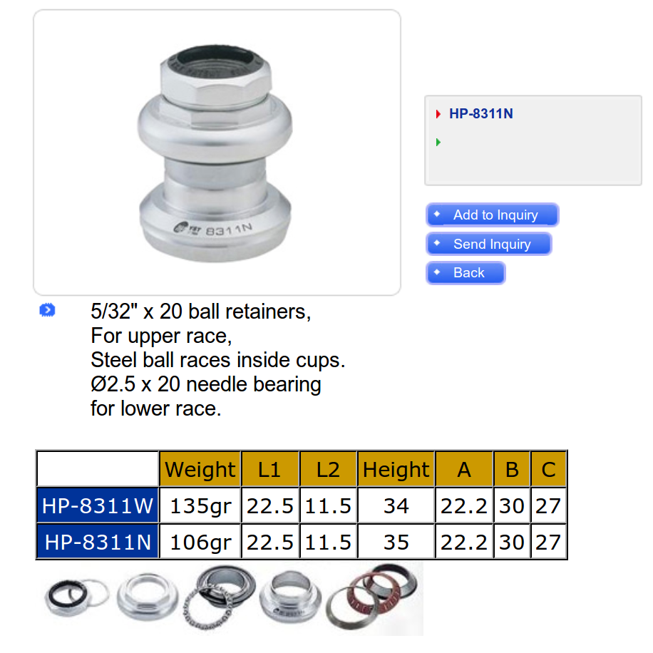
The lower bearing (a YST 8311N in black) has rollers, not balls. The headset has J.I.S. 1 inch dimensions, captured in a screen grab to forestall link rot:
YST 8311N headset data
Which means cheap & readily available ISO standard headsets aren’t a drop-in replacement. The incomparable Harris Cyclery has J.I.S. ball-bearing headsets in stock and their Tange Levin CDS HD1002 needs just 1.6 mm of additional washer to match the YST’s 35 mm stack height…
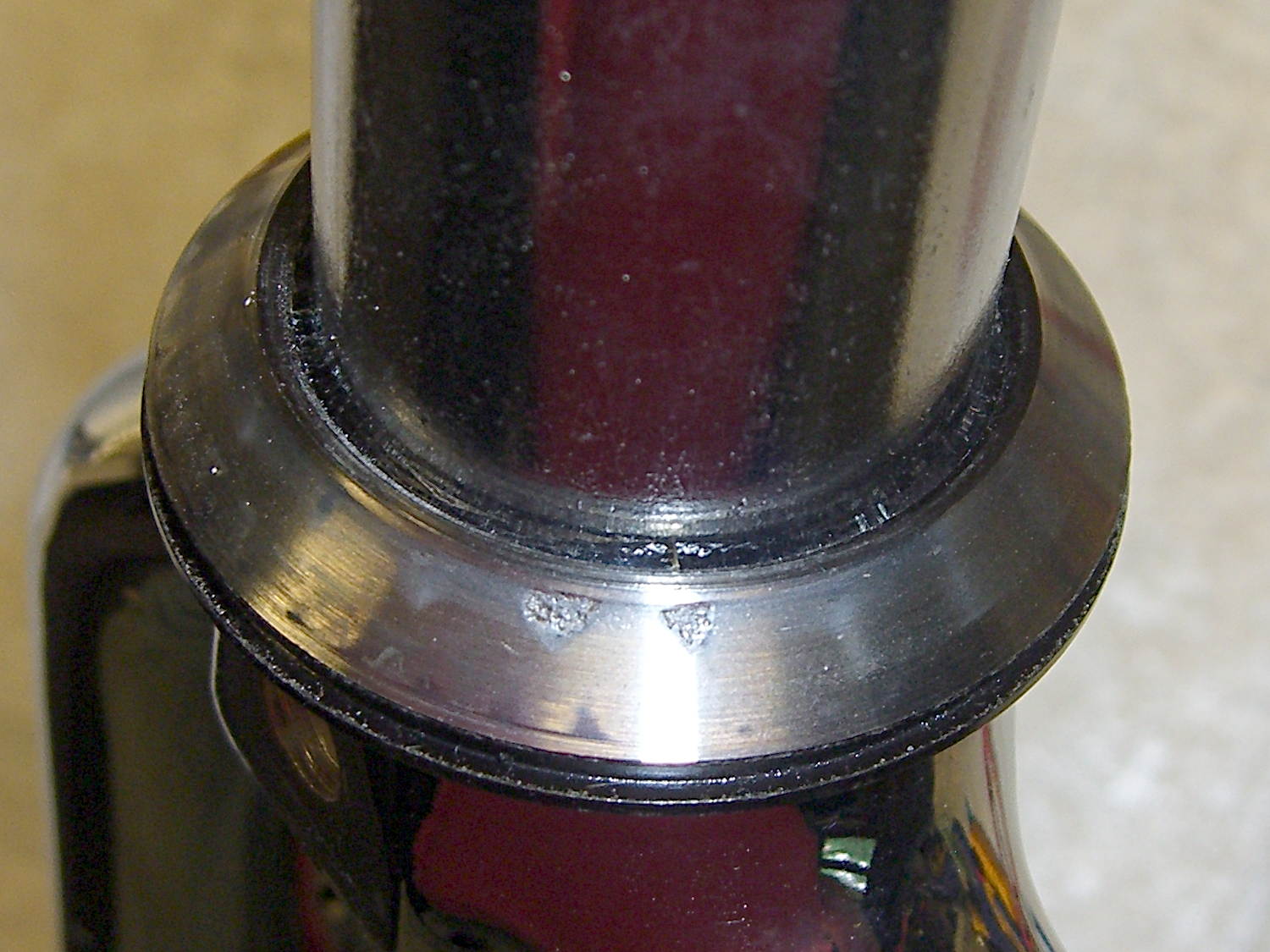
The front side of the crown got rather graunched over the last 14 years, but I punted the problem by rotating the race half a turn to put the eroded spots toward the rear, where they’ll be under minimal stress:
Tour Easy crown bearing – damage
Re-seating the race brought an ancient Headsetter tool from the drawer:
Tour Easy fork with Headsetter
It’s basically galvanized pipe, chamfered on one end, with a set of nuts & washers on a length of all-thread rod just slightly too short for the occasion: this might be the second time I’ve used the thing and I had to supply my own all-thread & nuts. Ah, well, it probably predates the Tour Easy’s design by a decade.
The lower headset race looked to be in pretty good shape, so I left it alone. Normally, such bearing damage gives you indexed steering, but Tour Easy handlebars provide so much lever arm that nothing interferes with the bike’s steering.
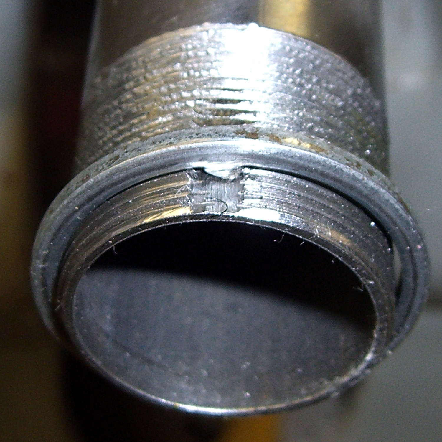
The new fork didn’t have a notch for the keyed washer isolating the locknut from the upper bearing race. The usual advice is to file off the key and apply threadlocker, which makes adjusting the two nuts tedious, so I restored the notch in the steerer threads:
Tour Easy – filed steerer tube key slot
Yes, that’s a lethally sharp steel shaving from the not-very-well-reamed ID curling up in the middle of the notch.
The fender mount bridge on the new fork sits half an inch higher in relation to the brake bosses, putting the fender against the V-brake cable hardware. Anything touching the V-brake messes up the pad-to-rim alignment, so I conjured a snippet of aluminum to lower the fender just enough to clear the brakes:
Tour Easy – new fork – fender extender
I think that calls for a nice 3D printed bracket, too, but the snippet got me back on the bike faster. When I preemptively replace the fork on Mary’s bike, then I’ll do a proper bracket for both of us.
The garish red silicone tape replaces the previous black cable ties. It matches the tube paint surprisingly well and doesn’t look good on the fork, so I’ll replace it with cable ties in due course.
A few miles of shakedown riding settled the crown race against the fork, another 1/6 turn of the upper race / lock nut snugged up the bearings, and it’s all good again.
Wow, it’s great to be back on the bike!
(Due to the vagaries of writing this stuff up ahead of time, there’s actually two weeks of realtime between the post that appeared on Monday and this one.)
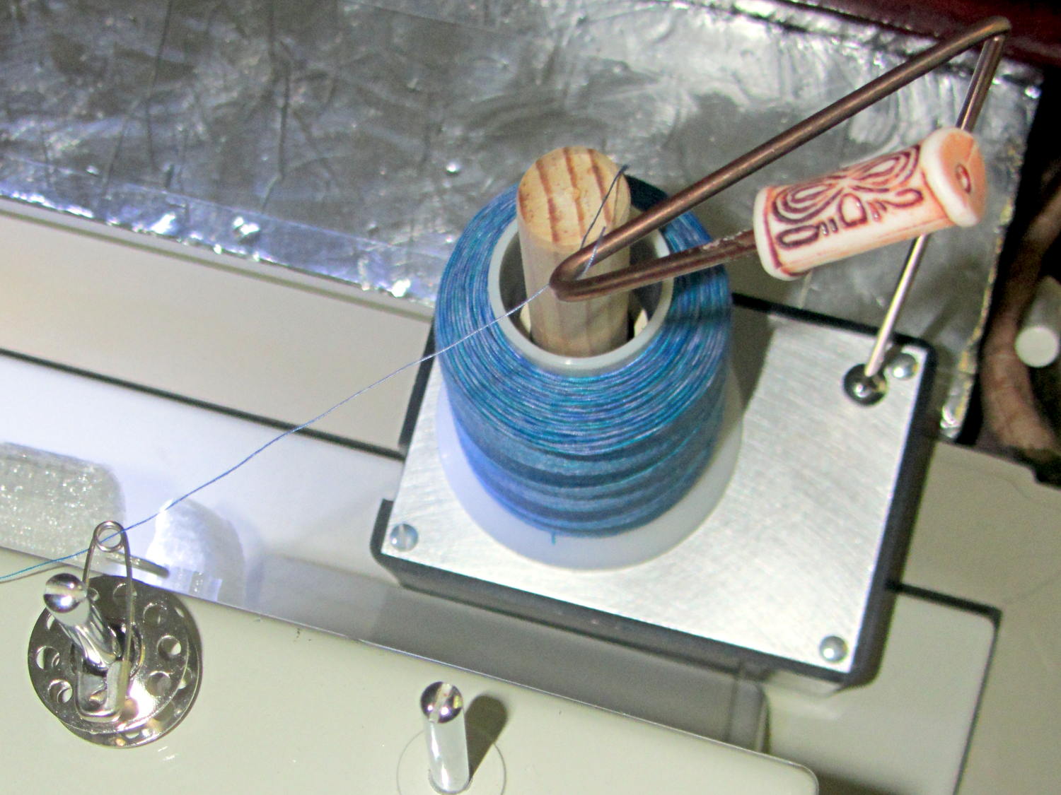
I’d rounded the end of that steel rod, it stands behind the sewing machine, and blah blah blah. He was right: it needed a bead. That’s a fancy one pilfered from our Larval Engineer’s stash, held in place by a blob of fast-cure epoxy.
Selah.
The safety pin atop the bobbin on the left spool pin feeds the thread into the machine’s upper thread guide at the proper angle to make it all work; a direct line from the spool holder hook isn’t quite right.
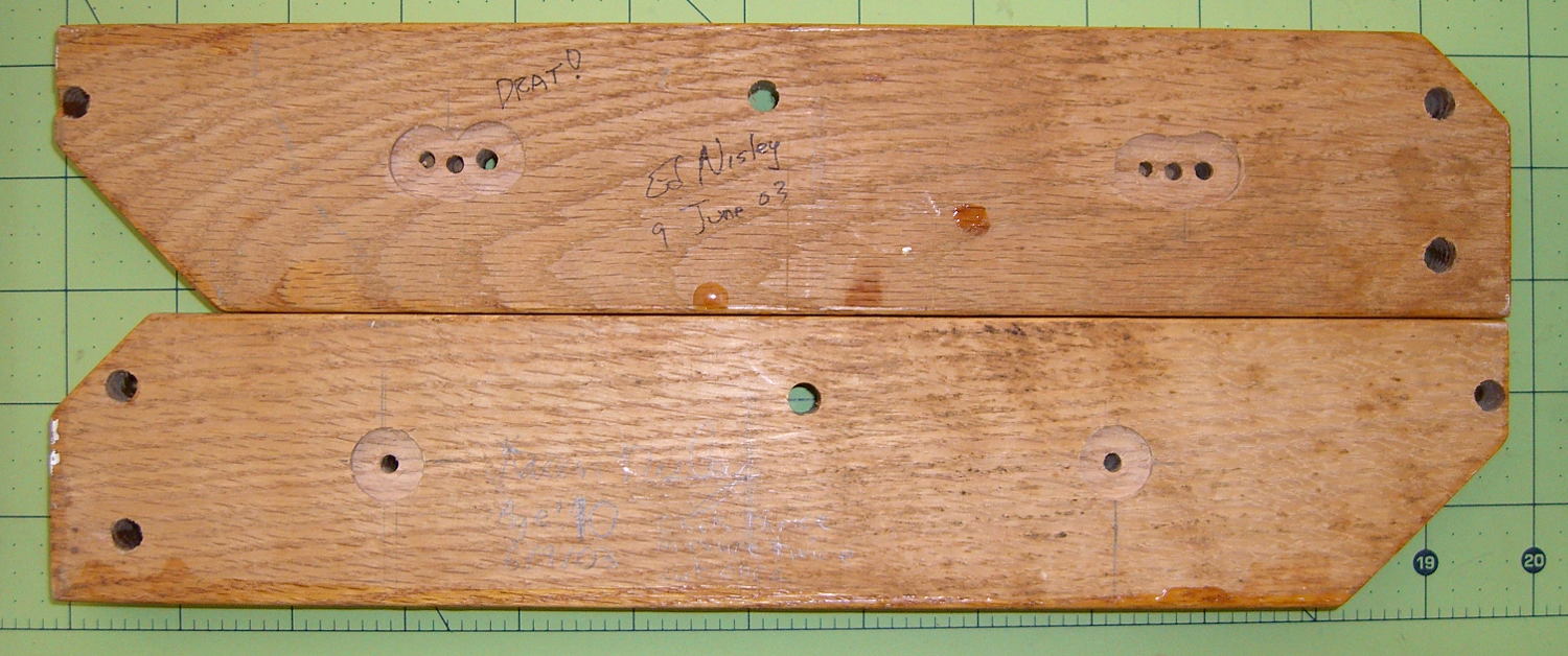
Quite some years ago, I added a wire shelf to the bottom of the “pantry” closet to hold odds-and-ends. The most recent deep-cleaning cycle required removing the shelf, which required removing the mounting brackets to get the fool thing out of the closet.
The backside of one bracket shows I had a bit of trouble matching the mounting holes to the wall anchors:
Pantry wire shelf brackets – overview
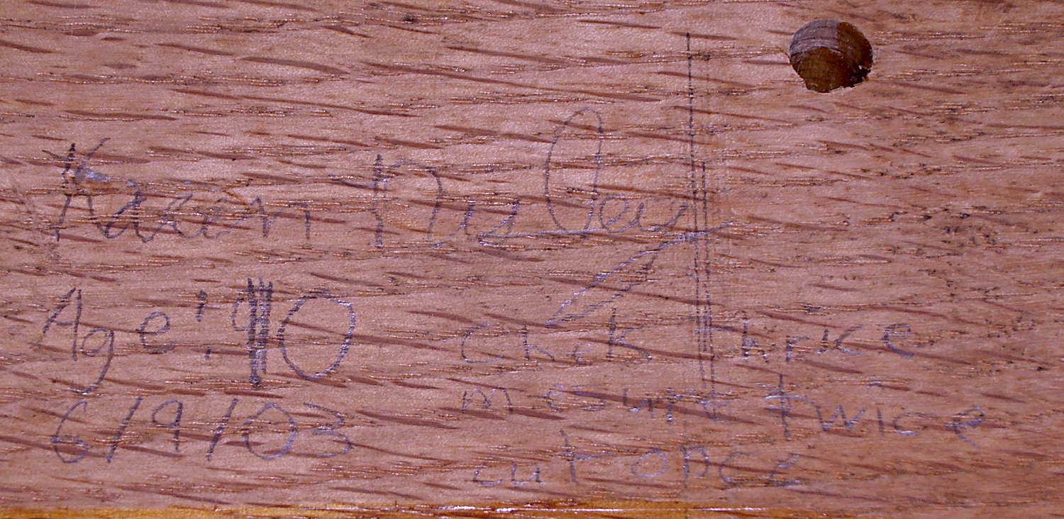
The lower bracket bears some advice from my Shop Assistant:
Pantry wire shelf brackets – detail
Check thrice
Measure twice
Cut once
From what little we hear these days, she’s learned the value of always checking her work…
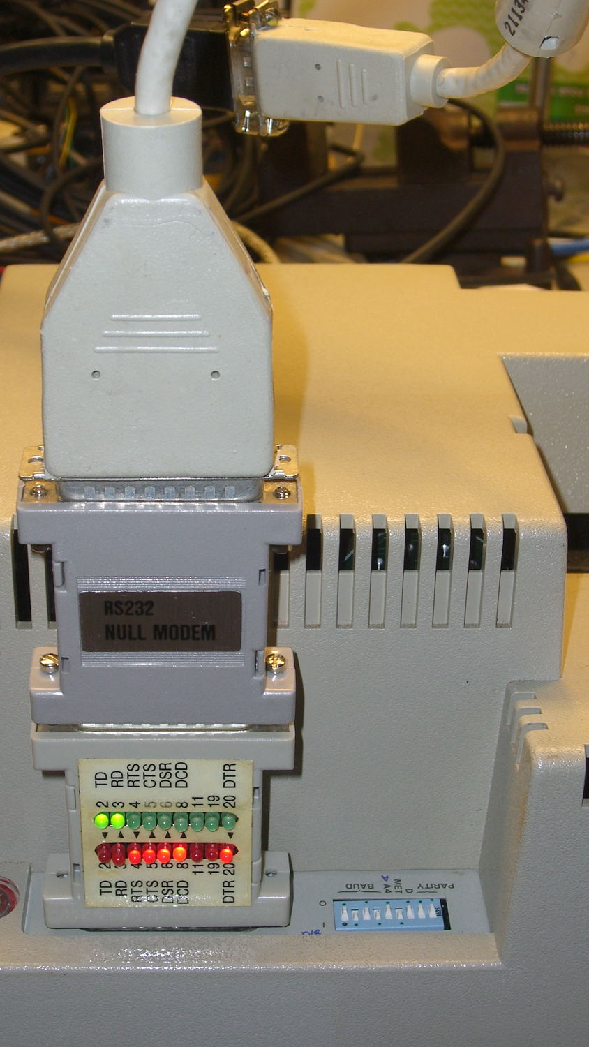
Chiplotle seems like a good way to drive the HP 7475A plotter, but some preliminary tinkering showed that the plotter pen paused quite regularly while drawing. The plotter wakes up with hardware handshaking enabled, Chiplotle has a config file that lets you specify hardware handshaking, the cable has all the right connections for hardware handshaking, but peering at Der Blinkenlights showed hardware handshaking never happened: the data didn’t overrun, the buffer never filled up, and DTR remained solidly on.
Come to find out that Chiplotle sends data in half-buffer-size chunks (all code from baseplotter.py):
class _BasePlotter(object):
   def __init__(self, serial_port):
      self.type = '_BasePlotter'
      self._logger = get_logger(self.__class__.__name__)
      self._serial_port = serial_port
      self._hpgl = commands
      self._margins = MarginsInterface(self)
      self.maximum_response_wait_time = get_config_value('maximum_response_wait_time')

      #this is so that we don't pause while preparing and sending
      #full buffers to the plotter. By sending 1/2 buffers we assure
      #that the plotter will still have some data to plot while
      #receiving the new data
      self.buffer_size = int(self._buffer_space / 2)
      self.initialize_plotter( )
Every time something goes out to the plotter, this happens:
   def _write_string_to_port(self, data):
      ''' Write data to serial port. data is expected to be a string.'''
      #assert type(data) is str
      if not isinstance(data, basestring):
         raise TypeError('string expected.')
      data = self._filter_unrecognized_commands(data)
      data = self._slice_string_to_buffer_size(data)
      for chunk in data:
         self._sleep_while_buffer_full( )
         self._serial_port.write(chunk)
In order to figure out whether the plotter has enough room, Chiplotle must ask it:
   def _sleep_while_buffer_full(self):
      '''
         sleeps until the buffer has some room in it.
      '''
      if self._buffer_space < self.buffer_size:
         while self._buffer_space < self.buffer_size:
            time.sleep(0.01)
The self._buffer_space method contains the complete handshake:
Assuming that Python can actually meter out a 0.01 second sleep, that’s a mere 10 ms; call it 10 character times at 9600 b/s. By and large, Chiplotle hammers away at the poor plotter while the buffer drains.
Now, that would be just ducky, except that the HP 7475A plotter dates back to slightly after microcontrollers were invented. The MC6802 trundles along at 1 MHz from a 4 MHz crystal, because it needed a quadrature clock, and takes a while to get things done. Responding to the buffer space request (a three-character sequence: ␛.B) requires the plotter to:
Stop plotting
Answer the phone
Figure out what to do
Compose a reply
Drop it in the serial buffer
Resume plotting
Which take enough time to produce a distinct hitch in the gitalong. Some crude print debugging showed most of the delay happens between the write() and the read() tucked inside _buffer_space.
Linux handles serial port hardware handshaking far below the Python level, so the simplest fix was to rip out the line that checks for enough buffer space:
   def _write_string_to_port(self, data):
      ''' Write data to serial port. data is expected to be a string.'''
      #assert type(data) is str
      if not isinstance(data, basestring):
         raise TypeError('string expected.')
      data = self._filter_unrecognized_commands(data)
      data = self._slice_string_to_buffer_size(data)
      for chunk in data:
#         self._sleep_while_buffer_full( )
         self._serial_port.write(chunk)
And then the plotter races along without pauses, drawing as fast as it possibly can, with the DTR output blinking like crazy as Chiplotle dumps the character stream into the output buffer and the serial port hardware (*) managing the data flow. Apparently, detecting a buffer-full situation and dropping the DTR output requires only a few 6802 CPU cycles, which is what makes hardware handshaking such a good idea.
(*) Which is, of course, a USB-to-RS232 converter. I paid extra to get one that reports an FTDI chipset, which may mean the counterfeiters have upped their game since the Windows driver disaster. I actually tried it on the Token Windows box and it still works, so maybe it’s Genuine FTDI.
The HP 7475A wakes up with hardware handshaking enabled: DTR starts high and goes low when the internal 1 KB buffer has less than 80 bytes remaining. The plotter also supports XON/XOFF handshaking, a sad software thing you’d use only if you had no other choice.
The color codes over on the left of the top diagram match a prebuilt cable I hoped to repurpose, but it had only five conductors, none of which were DSR or CTS. Pfui!
So I used a hank of gorgeous flexy 9-conductor cable (which came with premolded DE-9 ends of the wrong gender, now amputated into pigtails and back in the GCS), which supported the connections redrawn on the bottom in proper numeric order, used the obvious color sequence (Bn R O Y G Bl V W K), then soldered suitable connectors on each end:
The effort those little birds put into their nests never ceases to amaze me:
Bird box cleanout – old nests
Last year it was the same story. Of course, if we didn’t clean out the boxes, the birds would do it on their own, so perhaps we help them get started earlier.
The objective being to wrap a nose around the cutter blade to allow some control over the cut depth, I lengthened the cylinder around the cutter body and modeled a discrete glue-on cap:
Roland knife stabilizer and nose – show
Which, with an additional 80 g of ballast, worked fine in the double-thick vinyl:
Roland knife stabilizer – nut weight
The pen-lift spring can just barely manage to heave that load off the vinyl, but it’s obviously running at the limit of its ability and this can’t possibly be a Good Thing for the mechanism in the long run.
After a bit more fiddling around, I noticed that the stabilizer wasn’t sitting flat on the pen holder and that there really wasn’t any good reason to have a separate cap, so I did one more revision:
Roland knife stabilizer with nose – side view
The cutaway view shows the knife model now has tapered transition from the body to the grossly enlarged blade, so the model will build without supports inside the cylinder.
A little cutout on one wall lets the plate sit flat on the pen holder and a barely visible recess in the cylinder gives the carousel pen-capping actuator a bit more clearance:
Roland knife stabilizer with nose – Slic3r preview
It works about as well as the version shown above, minus the tedious gluing, so I’ll call it a success… even though it’s obviously not going to get much use. I don’t see any way to apply enough downforce to make the cutter work; the mechanical changes just aren’t worthwhile.
The OpenSCAD source code, which includes some tweaks and outright kludges since the first version, builds adapters for Sakura pens (which work just fine) as well as this knife stabilizer:
// HP 7475A plotter pen adapters
// Ed Nisley KE4ZNU April 2015

Layout = "BuildStabilizer";
							// ShowBody BuildBody BodyPoly
							// ShowPen ShowPenAdapter BuildPenAdapter Plug Pen PenPoly
							// ShowKnife BuildKnife KnifeAdapter Knife
							// ShowStabilizer Stabilizer BuildStabilizer

//- Extrusion parameters must match reality!

ThreadThick = 0.25;
ThreadWidth = 0.40;

HoleWindage = 0.2;

Protrusion = 0.1;			// make holes end cleanly

inch = 25.4;

function IntegerMultiple(Size,Unit) = Unit * ceil(Size / Unit);

//----------------------
// Dimensions
// Z=0 at pen tip!

NumSides = 8*4;						// number of sides on each "cylinder"

RADIUS = 0;							// subscript for radius values
HEIGHT = 1;							//   ... height above Z=0

//-- Original HP plotter pen, which now serves as a body for the actual pen

BodyOutline = [						// X values = (measured diameter)/2, Y as distance from tip
	[0.0,0.0],						//  0 fiber pen tip
//	[2.0/2,1.4],					//  1 ... taper (not buildable)
	[1.0/2,0.005],					//  1 ... faked point to remove taper
	[2.0/2,0.0],[2.0/2,2.7],		//  2 ... cylinder
	[3.7/2,2.7],[3.7/2,4.45],		//  4 tip surround
	[4.8/2,5.2],					//  6 chamfer
	[6.5/2,11.4],					//  7 rubber seal face
	[8.9/2,11.4],					//  8 cap seat
	[11.2/2,15.9],					//  9 taper to body
	[11.5/2,28.0],					// 10 lower body
	[13.2/2,28.0],[16.6/2,28.5],	// 11 lower flange = 0.5
	[16.6/2,29.5],[13.2/2,30.0],	// 13 flange rim = 1.0
	[11.5/2,30.0],					// 15 upper flange = 0.5
	[11.5/2,43.25],					// 16 upper body
	[0.0,43.25]						// 17 lid over reservoir
	];

TrimHeight = BodyOutline[9][HEIGHT];		// cut off at top of lower taper
SplitHeight = (BodyOutline[11][HEIGHT] + BodyOutline[14][HEIGHT])/2;	// middle of flange

FlangeOD = 2*BodyOutline[13][RADIUS];
FlangeTop = BodyOutline[15][HEIGHT];

BodyOD = 2*BodyOutline[16][RADIUS];
BodyOAL = BodyOutline[17][HEIGHT];

echo(str("Trim: ",TrimHeight));
echo(str("Split: ",SplitHeight));

BuildSpace = FlangeOD;

//-- Sakura Micron fiber-point pen

ExpRP = 0.15;						// expand critical sections (by radius)

//-- pen locates in holder against end of outer body

PenOutline = [
	[0,0],							//  0 fiber pen tip
	[0.6/2,0.0],[0.6/2,0.9],		//  1  ... cylinder
	[1.5/2,0.9],[1.5/2,5.3],		//  3 tip surround
	[4.7/2,5.8],					//  5 chamfer
	[4.9/2,12.3],					//  6 nose
//	[8.0/2,12.3],[8.0/2,13.1],		//  7 latch ring
//	[8.05/2,13.1],[8.25/2,30.5],	//  9 actual inner body
	[8.4/2 + ExpRP,12.3],[8.4/2 + ExpRP,30.5],	//  7 inner body - clear latch ring
	[9.5/2 + ExpRP,30.5],			//  9 outer body - location surface!
	[9.8/2 + ExpRP,50.0],			// 10 outer body - length > Body
	[7.5/2,50.0],					// 11 arbitrary length
	[7.5/2,49.0],					// 12 end of reservoir
	[0,49.0]						// 13 fake reservoir
	];

PenNose = PenOutline[6];
PenLatch = PenOutline[7];

PenOAL = PenOutline[11][HEIGHT];

//-- Plug for end of cut-off pen body
//   you need two plugs...

PlugOutline = [
	[0,0],							// 0 center of lid
	[9.5/2,0.0],[9.5/2,1.0],		// 1 lid rim <= body OD
	[7.9/2,1.0],					// 3 against end of pen
	[7.6/2,6.0],					// 4 taper inside pen body
	[5.3/2,6.0],					// 5 against ink reservoir
	[4.0/2,1.0],					// 6 taper to lid
	[0.0,1.0]						// 7 flat end of taper
	];

PlugOAL = PlugOutline[5][HEIGHT];

//   cap locates against end of inner body at latch ring
//-- cap origin is below surface to let pen tip be at Z=0

CapGap = 1.0;						// gap to adapter body when attached
CapGripHeight = 2.0;				// thickness of cap grip flange
CapTipClearance = 1.0;				// clearance under fiber tip

CapOffset = -(CapGripHeight + CapTipClearance);	// align inside at pen tip Z=0

CapOutline = [
	[0,CapOffset],									// 0 base
	[FlangeOD/2,CapOffset],							// 1 finger grip flange
	[FlangeOD/2,CapOffset + CapGripHeight],			// 2  ... top
	[BodyOD/2,CapOffset + CapGripHeight],			// 3 shaft
	[BodyOD/2,TrimHeight - CapGap],					// 4  ... top with clearance
	[PenLatch[RADIUS],TrimHeight - CapGap],			// 5 around pen latch ring
	[PenLatch[RADIUS],PenNose[HEIGHT]],				// 6  ... location surface!
	[PenNose[RADIUS] + ExpRP,PenNose[HEIGHT]],		// 7 snug around  nose
	[PenNose[RADIUS] + ExpRP,-CapTipClearance],		// 8 clearance around tip
	[0,-CapTipClearance],							// 9  ... bottom
	];

//-- Roland drag knife bearing assembly

ExpRK = 0.30;						// expand critical sections (by radius)
AdjLen = 2.0;						// allowance for adjustment travel

//- Knife tweaked for pen adapter
/*
KnifeOutline = [
	[0,0],							//  0 blade point (actually 0.25 mm offset)
	[1.0/2,0.0],					//  1  ... blunt end
	[1.0/2,4.0],					//  2  ... cylinder
	[2.0/2,4.0],					//  3 blade shank
	[2.0/2,5.9],					//  4  .. at bearing
	[6.0/2,5.9],					//  5 holder - shell

	[7.3/2 + ExpRK,8.3],			//  6 holder - taper to body
	[7.3/2 + ExpRK,21.0 - AdjLen],	//  7 holder body

	[8.8/2 + ExpRK,22.0 - AdjLen],	//  8 holder - threads bottom
	[8.8/2 + ExpRK,25.0],[9.0/2 + ExpRK,26.0],		//  9 clear threads to reduce friction
	[9.0/2 + ExpRK,32.0],[8.8/2 + ExpRK,33.0],		// 11  ... end clearance
	[8.8/2 + ExpRK,42.5 - AdjLen],	// 13 holder - threads top = locknut bottom
	[12.5/2,42.5 - AdjLen],			// 14 knurled locknut - adjustment travel
	[12.5/2,45.8],					// 15 knurled locknut - top
	[11.0/2,45.8],					// 16 holder - adjusting knurl
	[11.0/2,52.0],					// 17 holder - top surface
	[3.0/2,52.0],[3.0/2,57.2],		// 18 spring post
	[0.0,57.2]						// 19 end of post
	];
*/

//- Knife tweaked for stabilizer

KnifeOutline = [
	[0,0],							//  0 blade point (actually 0.25 mm offset)
	[3.0/2,0.0],					//  1  ... blunt end
	[3.0/2,4.0],					//  2  ... cylinder
	[3.0/2,4.0],					//  3 blade shank
	[6.0/2,5.9],					//  4  .. at bearing (taper to support nose)
	[6.0/2,5.9],					//  5 holder - shell

	[7.3/2 + ExpRK,8.3],			//  6 holder - taper to clear threads
	[7.3/2 + ExpRK,21.0 - AdjLen],	//  7  ..

	[8.8/2 + ExpRK,22.0 - AdjLen],	//  8 holder - threads bottom
	[8.8/2 + ExpRK,25.0],[9.0/2 + ExpRK,26.0],		//  9 clear threads to reduce friction
	[9.0/2 + ExpRK,32.0],[8.8/2 + ExpRK,33.0],		// 11  ... end clearance

	[8.8/2 + ExpRK,42.5 - AdjLen],	// 13 holder - threads top = locknut bottom
	[12.5/2,42.5 - AdjLen],			// 14 knurled locknut - adjustment travel
	[12.5/2,45.8],					// 15 knurled locknut - top
	[11.0/2,45.8],					// 16 holder - adjusting knurl
	[11.0/2,52.0],					// 17 holder - top surface
	[3.0/2,52.0],[3.0/2,57.2],		// 18 spring post
	[0.0,57.2]						// 19 end of post
	];

ThreadStart = KnifeOutline[8][HEIGHT];
ThreadOD = 2*KnifeOutline[11][RADIUS];

//-- Plotter pen holder stabilizer

HolderPlateThick = 3.0;				// thickness of plate atop holder
RimHeight = 5.0;					// rim around sides of holder
RimThick = 2.0;						// wall thickness

HolderOrigin = [17.0,12.2,0.0];		// center of pen tip relative to polygon coordinates

HolderHeight = 30.0;				// top of holder to platen in pen-down position
HolderTopThick = 1.7;				// top of holder to top of pen flange

HolderNoseLength = 4.0;				// length of nose taper
HolderKnifeOffset = -3.0;			// additional downward adjustment range

LockScrewInset = 3.0;				// from right edge of holder plate
LockScrewOD = 2.0;					// tap for 2.5 mm screw

UncapperHeight = -17.0;				// uncapping actuator arm from top of pen holder
UncapperOD = 11.0;					//  ... max OD that clears uncapper

// Beware: update hardcoded subscripts in Stabilizer() when adding / deleting point entries

HolderPlate = [
	[8.6,18.2],[8.6,23.9],			// 0 lower left corner of pen recess
	[13.9,23.9],[13.9,30.0],		// 2
//	[15.5,30.0],[15.5,25.0],		// 4 omit middle of support beam
//	[20.4,25.0],[20.4,30.0],		// 6
	[22.7,30.0],[22.7,27.5],		// 4
	[35.8,27.5],[35.8,20.7],		// 6 spring box corner
	[43.0,20.7],					// 8
	[31.5,0.0],						// 9
//	[24.5,0.0],[24.5,8.0],			// 10 omit pocket above pen clamp
//	[22.5,10.0],[22.5,16.5],		// 12
//	[20.5,18.2]						// 14
	[13.6,0.0],						// 10
	[8.6,5.0]						// 11
	];

BeamWidth = HolderPlate[4][0] - HolderPlate[2][0];		// rear support beam

TabWidth = HolderPlate[1][1] - HolderPlate[0][1];		// tab extending left beyond pen recess
TabClear = 3.0;											// maximum rim height over tab

HolderCylinderOutline = [
	[0,0],											//  0 center of nose
	[6.0/2,0.0],									//  1 flat nose surface OD
	[BodyOD/2,HolderNoseLength],			//  2 taper to cylinder OD
	[BodyOD/2,HolderHeight],				//  3 cylinder to top of holder plate
	[0,HolderHeight]								//  4 flat top
	];

//----------------------
// Useful routines

module PolyCyl(Dia,Height,ForceSides=0) {			// based on nophead's polyholes

  Sides = (ForceSides != 0) ? ForceSides : (ceil(Dia) + 2);

  FixDia = Dia / cos(180/Sides);

  cylinder(r=(FixDia + HoleWindage)/2,
           h=Height,
	   $fn=Sides);
}

//- Locating pin hole with glue recess
//  Default length is two pin diameters on each side of the split

PinOD = 1.75;
PinOC = BodyOD / 2;

module LocatingPin(Dia=PinOD,Len=0.0) {

	PinLen = (Len != 0.0) ? Len : (4*Dia);

	translate([0,0,-ThreadThick])
		PolyCyl((Dia + 2*ThreadWidth),2*ThreadThick,4);

	translate([0,0,-2*ThreadThick])
		PolyCyl((Dia + 1*ThreadWidth),4*ThreadThick,4);

	translate([0,0,-(Len/2 + ThreadThick)])
		PolyCyl(Dia,(Len + 2*ThreadThick),4);

}

module LocatingPins(Length) {
	for (i=[-1,1])
	translate([0,i*PinOC/2,0])
		rotate(180/4)
		LocatingPin(Len=Length);
}

//----------------------
// Basic shapes

//-- HP plotter pen body

module ShowPolygon(pts) {
	polygon(pts);
}

module Body() {
	render(convexity=3)
		rotate_extrude($fn=NumSides)
			polygon(points=BodyOutline);
}

//-- Sakura drawing pen body

module Pen() {
	rotate_extrude($fn=NumSides)
		polygon(points=PenOutline);
}

//-- Plug for top of Sakura pen

module Plug() {
	render(convexity = 2)
		rotate_extrude($fn=NumSides)
			polygon(points=PlugOutline);
}

//-- Cap for tip of Sakura pen

module Cap() {
	render(convexity = 2)
		rotate_extrude($fn=NumSides)
			polygon(points=CapOutline);
}

//-- Sakura pen adapter

module PenAdapter() {

	render(convexity=3)
		difference() {
			Body();
			Pen();
			translate([0,0,TrimHeight/2])
				cube([2*FlangeOD,2*FlangeOD,TrimHeight],center=true);
		}
}

//-- Roland knife body

module Knife() {
	render(convexity=3)
		rotate_extrude($fn=NumSides)
			polygon(points=KnifeOutline);
}

//-- Roland knife adapter

module KnifeAdapter(TrimZ = false) {

Trans = TrimZ ? - TrimHeight : 0;

	render(convexity=5)
		translate([0,0,Trans])
			difference() {
				Body();
				Knife();
				translate([0,0,TrimHeight/2])
					cube([2*FlangeOD,2*FlangeOD,TrimHeight],center=true);
			}
}

//-- nose cap for stabilizer cylinder

module StabilizerNose() {
	render(convexity = 2)
		rotate_extrude($fn=NumSides)
			polygon(points=StabilizerNoseOutline);
}

//-- Roland knife stabilizer atop pen holder
//   the trim blocks have offsets with magic numbers from the HolderPlate outline &c

module Stabilizer(SeeKnife = false) {

Cutout = (Layout == "ShowStabilizer") ? 0 : 1;

	difference() {
		union() {
			translate(-HolderOrigin)													// put center of pen at origin
			translate([0,0,-RimHeight])													// put top of holder at Z=0
				difference() {
						render(convexity=4)
						linear_extrude(height=(HolderPlateThick + RimHeight))			// overall flange around edges
							offset(r=RimThick)
									polygon(points=HolderPlate);

						render(convexity=4)
						translate([0,0,-Protrusion])									// recess for pen holder plate
							linear_extrude(height=(RimHeight + Protrusion))
								polygon(points=HolderPlate);

						translate([HolderPlate[7][0] - Protrusion,HolderPlate[7][1] - Protrusion,-Protrusion])	// trim spring box from top plate
							cube([30,20,(RimHeight + HolderPlateThick + 2*Protrusion)]);

						translate([27.0,HolderPlate[6][1] - Protrusion,-Protrusion])	// trim pivot plate clearance
							cube([30,20,(RimHeight + HolderPlateThick + 2*Protrusion)]);

						translate([HolderPlate[2][0],20,-Protrusion])					// trim left support beam
							cube([BeamWidth,20,(RimHeight + Protrusion)]);

						translate([0,HolderPlate[0][1],-(TabClear + Protrusion)])		// trim tab behind pen recess
							cube([(HolderPlate[0][0] + Protrusion),TabWidth,RimHeight + Protrusion]);

						translate([HolderPlate[9][0] - LockScrewInset,RimThick,RimHeight - HolderTopThick - LockScrewOD/2])												// lock screw on front edge
							rotate([90,0,0])
								rotate(180/4)
									PolyCyl(LockScrewOD,3*RimThick);					// punch out hold-down screw hole
				}

			difference() {
				translate([0,0,-HolderHeight])											// cylinder and nose
					rotate_extrude($fn=NumSides)
						polygon(points=HolderCylinderOutline);
				translate([-HolderOrigin[0],-(BodyOD + Cutout*UncapperOD/2),(UncapperHeight - HolderHeight)])	// uncapper clearance
					cube([2*HolderOrigin[0],BodyOD,HolderHeight]);
			}
		}

		translate([0,0,-HolderHeight + HolderKnifeOffset])
			if (SeeKnife)
#				Knife();
			else
				Knife();

	}
}

//----------------------
// Build it

if (Layout == "Pen")
	Pen();

if (Layout == "Knife")
	Knife();

if (Layout == "Stabilizer")
	Stabilizer();

if (Layout == "ShowBody")
	Body();

if (Layout == "BodyPoly") {
	ShowPolygon(BodyOutline);
	Body();
}

if (Layout == "PenPoly") {
	ShowPolygon(PenOutline);
	Pen();
}

if (Layout == "BuildBody") {
	Spacing = 0.75*BuildSpace;
	difference() {
		union() {
			translate([Spacing,0,-SplitHeight])
				Body();
			rotate([180,0,0])
				translate([-Spacing,0,-SplitHeight])
					Body();
		}
		translate([0,0,-BodyOAL])
			cube(2*BodyOAL,center=true);
		for (i = [-1,1])
			translate([i*Spacing,0,0])
				LocatingPins(5.0);
	}
}

if (Layout == "Plug")
	Plug();

if (Layout == "KnifeAdapter")
	KnifeAdapter();

if (Layout == "ShowPen") {
	color("AntiqueWhite") {
		Pen();
		translate([-1.5*BodyOD,0,0])
			Pen();
	}
	color("Magenta",0.35) {
		translate([0,0,PlugOAL + PenOAL + 3.0])
			rotate([180,0,0])
				Plug();
		PenAdapter();
		Cap();
	}
	color("Magenta") {
		translate([1.5*BodyOD,0,PlugOAL + PenOAL + 3.0])
			rotate([180,0,0])
				Plug();
		translate([1.5*BodyOD,0,0]) {
			PenAdapter();
			Cap();
		}
	}
}

if (Layout == "ShowPenAdapter") {
	color("AntiqueWhite") {
		translate([0.00*BodyOD,0,0])
			Pen();
		translate([-2.75*BodyOD,0,0])
			Pen();
	}

	translate([-1.50*BodyOD,0,0])
		color("SandyBrown")
			Body();

	translate([0.00*BodyOD,0,0])
		color("SandyBrown",0.35)
			PenAdapter();

	translate([3.00*BodyOD,0,0])
		color("SandyBrown")
			PenAdapter();

	translate([1.50*BodyOD,0,0])
		difference() {
			color("SandyBrown")
				PenAdapter();
			translate([-BodyOD,-2*BodyOD,0])
				cube([2*BodyOD,2*BodyOD,PenOAL]);
		}

}

if (Layout == "ShowKnife") {

	color("Goldenrod") {
		Knife();
		translate([-1.5*BodyOD,0,0])
			Knife();
	}
	color("Magenta",0.35)
		KnifeAdapter();
	color("Magenta") {
		translate([1.5*BodyOD,0,0])
			KnifeAdapter();
	}

}

if (Layout == "BuildPenAdapter") {

	if (false) {
		for (j = [-1,1])
			translate([j*BuildSpace/2,-0.7*BuildSpace,0])
			Plug();

		translate([0,0,-CapOffset])
			Cap();
	}
	else {
		Plug();
	}

	difference() {
		union() {
			translate([1.20*BuildSpace,0,-SplitHeight])
				PenAdapter();
			rotate([180,0,0])
				translate([-1.20*BuildSpace,0,-SplitHeight])
					PenAdapter();
		}
		translate([0,0,-BodyOAL])
			cube(2*BodyOAL,center=true);
	}

}

if (Layout == "BuildKnife") {

	difference() {
		union() {
			translate([0.7*BuildSpace,0,-SplitHeight])
				KnifeAdapter(false);
			rotate([180,0,0])
				translate([-0.7*BuildSpace,0,-SplitHeight])
					KnifeAdapter(false);
		}
		translate([0,0,-BodyOAL])
			cube(2*BodyOAL,center=true);
	}

}

if (Layout == "BuildStabilizer") {

	translate([0,0,HolderPlateThick])
		rotate([0,180,0])
			Stabilizer(false);
}

if (Layout == "ShowStabilizer") {

	translate([BuildSpace/2,0,HolderHeight])
			Stabilizer(true);
	translate([-BuildSpace/2,0,HolderKnifeOffset])
		Knife();
}