Ed Nisley's Blog: Shop notes, electronics, firmware, machinery, 3D printing, laser cuttery, and curiosities. Contents: 100% human thinking, 0% AI slop.
Tag: Improvements
Making the world a better place, one piece at a time
Plotters date back to the days before companies started using DRM to protect their monopoly positions, so refilling plotter pens requires little more than prying out the plug and squirting in more ink. Refilling the disposable liquid ink pens and the green ceramic pen suggested this would work.
I shaved down the side of a Genuine HP pen to find out why the plug didn’t pop out. It turns out the plug has a long and aggressively ribbed profile to ensure a gas-tight fit:
HP Plotter Pen – exposed plug
The easiest way to refill those is to drill an off-center 1/16 inch hole in the plug, then inject ink into the sponge with a syringe and blunt needle (and bulk ink!) from an inkjet cartridge refill kit. Angling the needle through the sponge close to the pen wall, then filling slowly, loads the sponge from the bottom up and expels the air along the way.
Inmac pens have a shallow plug, more of a flat cap, that pries out with zero drama:
Inmac Plotter Pen – removed plug
Dripping the ink atop the sponge seems to work well, although that sponge is definitely over-filled.
Inmac caps push back in place with zero drama.
The pens have fiber nibs with vent channels along their sides that allow air into the reservoir, so overfilling the sponge nets you a mess when you take the cap off the nib: those same channels allow excess ink to run from the reservoir around the nib, without (much to my surprise) wetting the fiber tip.
About 0.2 ml of ink fills the reservoir to saturation, 0.1 ml leaves it wet, and 0.05 ml seems to work well. The 1.0 ml syringes I’m using require about 0.05 ml to fill the (blunt!) needle shaft & hub, plus the syringe tip below the 0.0 ml index, so measuring the ink by drops might make practical sense.
The old physician’s trick of expelling that air by inverting the syringe and pressing the plunger until liquid squirts from the needle is so not happening…
I’ve had zero success refilling fossilized pens, probably because the OEM ink slowly evaporating from the nib clogs all the gaps between the fibers with pigment or coagulated solvent. Preemptively refilling good pens when they first show signs of running dry generally works well.
Given the number of New Old Stock pens I have that are still in their original wrappers, this is more of a “Does it work?” exercise than a necessity.
But, y’know, maybe becoming the last plotter pen refiller on the planet will be my ticket to fame & fortune! For sure, we’ve all seen over-hyped Internet startups with worse business plans and (the admittedly few) typewriter repair shops occupy a stable niche.
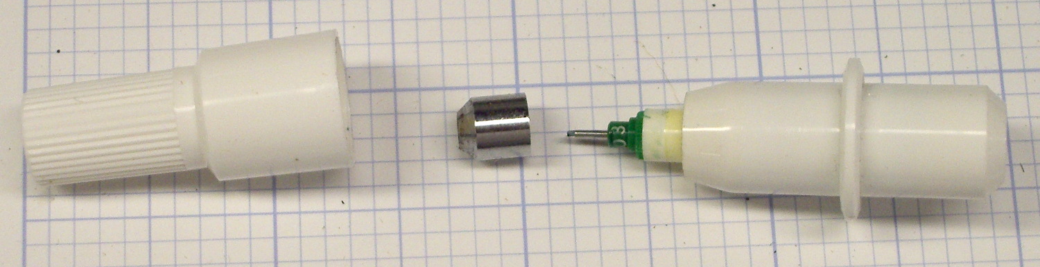
The ceramic-tip green pen I’ve been using finally ran dry and, having nothing to lose, I tried refilling it.
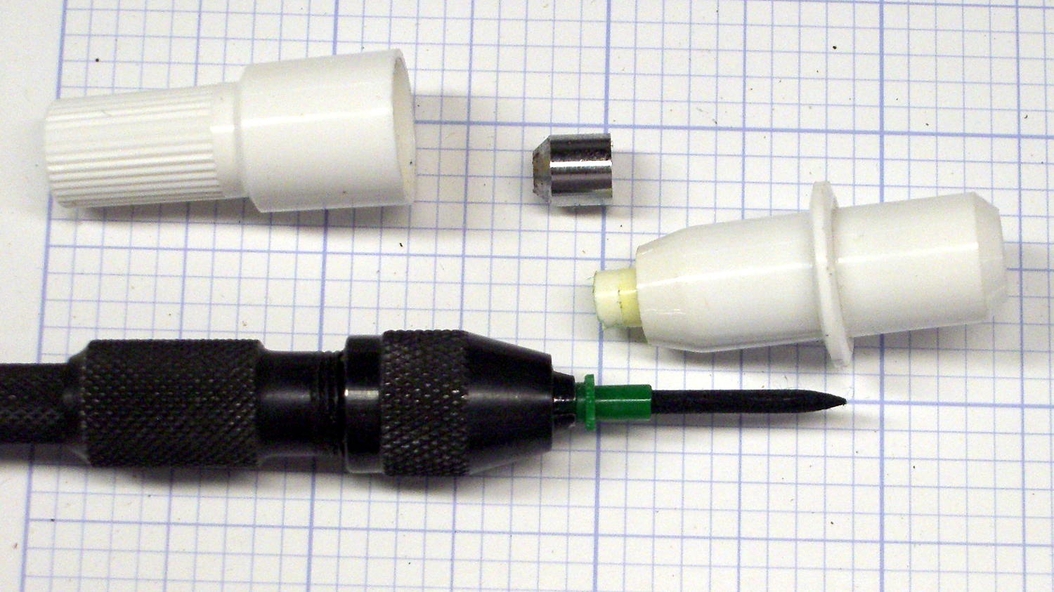
Grabbing the metal ferrule in the drill press chuck provided enough traction to twist / pull it off, revealing the pen nib assembly inside:
HP 7475A Ceramic-tip pen – ferrule
A pin vise provided enough traction to remove the nib, which had the expected fiber cylinder extending into the ink reservoir:
HP 7475A Ceramic-tip pen – disassembly
I injected 0.5 ml of yellow ink from my lifetime supply of bulk inkjet ink (*), then tried to inject 0.5 ml of cyan, which promptly overflowed. In retrospect, allowing a few minutes for the new ink to seep into whatever’s inside the reservoir would be prudent.
After wiping the mess off the pen and reassembling it in reverse order, it works just like new:
HP 7475A Ceramic-tip pen – C-Y refill
During the course of the first plot, the trace went from green to deep blue-green to a different green, which suggests the yellow ink took a while to make its presence known. No problem; whatever comes out of that tip is all good with me.
The stain around the rim of the pen body above the flange suggests a cap that might come off with sufficient persuasion. If it’s firmly fused to the flange, which would make perfect sense, injecting ink through a small hole drilled in the end might produce better results than ripping the nib out yet again.
(*) This leftover came from the never-sufficiently-to-be-damned HP2000C inkjet printer. ‘Nuff said.
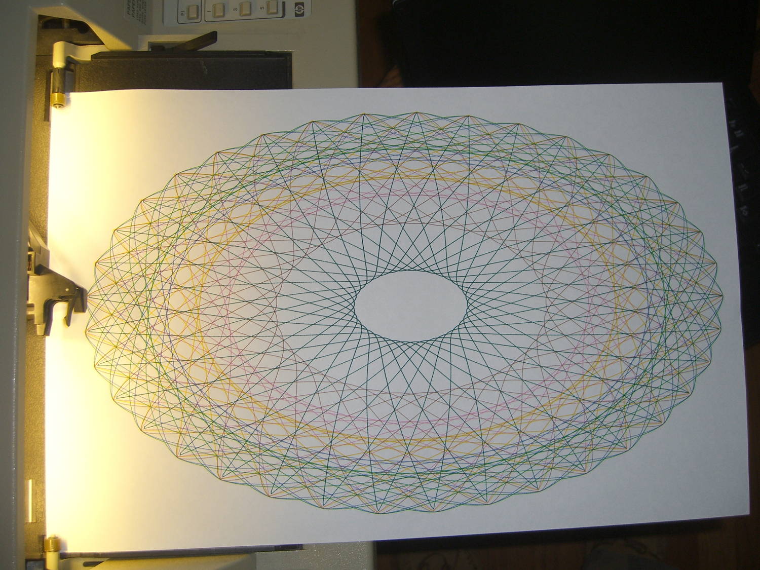
Setting n2=n3=1.5 generates smoothly rounded shapes, rather than the spiky ones produced by n2=n3=1.0, so I combined the two into a single demo routine:
HP 7475A – SuperFormula patterns
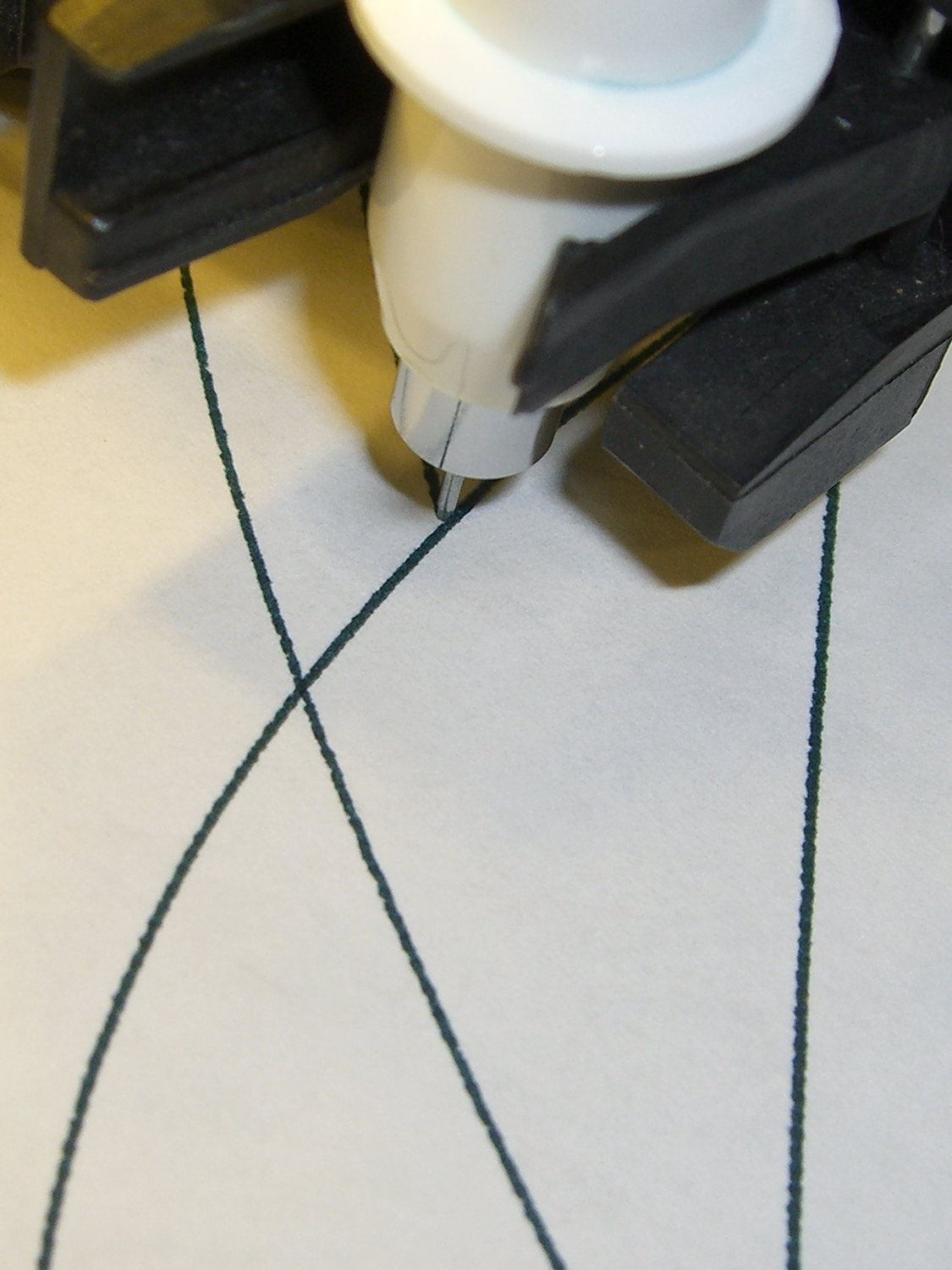
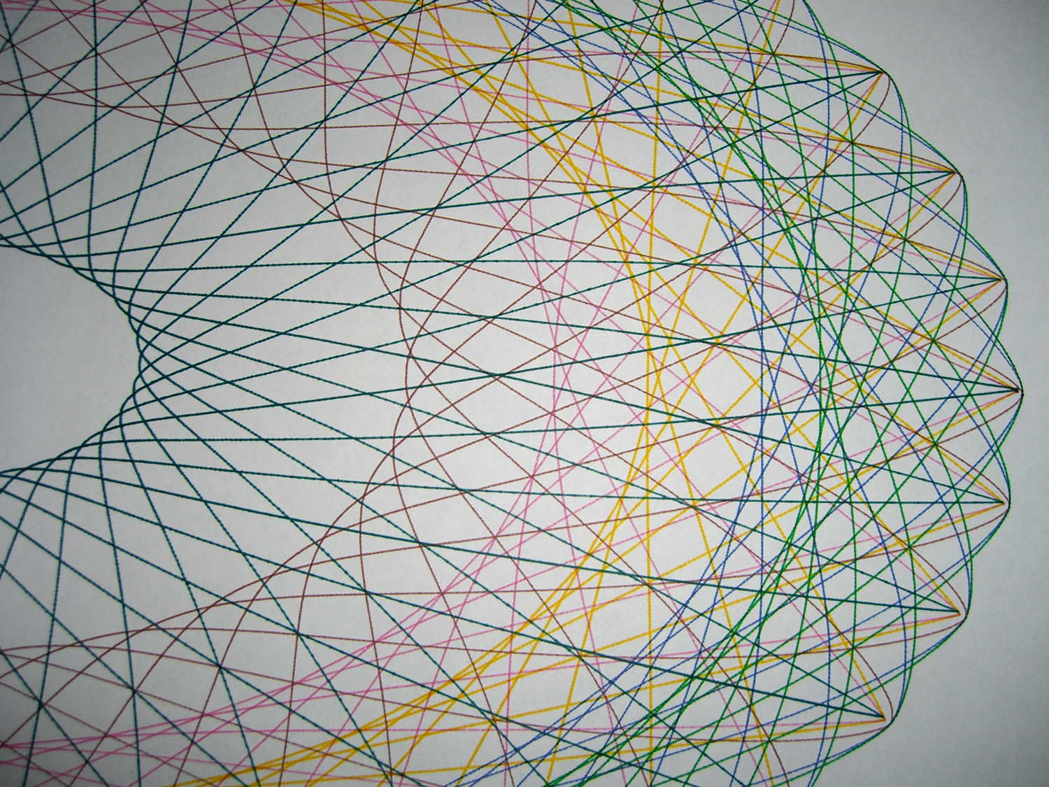
A closer look shows all the curves meet at the points, of which there are 37:
HP 7475A – SuperFormula patterns – detail
The spikes suffer from limited resolution: each curve has 10 k points, but if the extreme end of a spike lies between two points, then it gets blunted on the page. Doubling the number of points would help, although I think this has already gone well beyond the, ah, point of diminishing returns.
I used the three remaining “disposable” liquid ink pens for the spiked curves; the black pen was beyond repair. They produce gorgeous lines, although the magenta ink seems a bit thinned out by the water I used to rinse the remains of the last refill out of the spiral vent channel.
I modified the Chiplotle supershape() function to default to my choices for point_count and travel, then copied the superformula() function and changed it to return polar coordinates, because I’ll eventually try scaling the linear value as a function of the total angle, which is much easier in polar coordinates.
The demo code produces the patterns in the picture by iterating over interesting values of n1 and n2=n3, stepping through the pen carousel for each pattern. As before, m should be prime/10 to produce a prime number of spikes / bumps. You could add more iteration values, but six of ’em seem entirely sufficient.
A real demo should include a large collection of known-good parameter sets, from which it can pick six sets to make a plot. A legend documenting the parameters for each pattern, plus the date & time, would bolster the geek cred.
The Python source code with the modified Chiplotle routines:
from chiplotle import *
from math import *

def superformula_polar(a, b, m, n1, n2, n3, phi):
   ''' Computes the position of the point on a
   superformula curve.
   Superformula has first been proposed by Johan Gielis
   and is a generalization of superellipse.
   see: http://en.wikipedia.org/wiki/Superformula
   Tweaked to return polar coordinates
   '''

   t1 = cos(m * phi / 4.0) / a
   t1 = abs(t1)
   t1 = pow(t1, n2)

   t2 = sin(m * phi / 4.0) / b
   t2 = abs(t2)
   t2 = pow(t2, n3)

   t3 = -1 / float(n1)
   r = pow(t1 + t2, t3)
   if abs(r) == 0:
      return (0,0)
   else:
 #     return (r * cos(phi), r * sin(phi))
     return (r,phi)

def supershape(width, height, m, n1, n2, n3,
   point_count=10*1000, percentage=1.0, a=1.0, b=1.0, travel=None):
   '''Supershape, generated using the superformula first proposed
   by Johan Gielis.

   - `points_count` is the total number of points to compute.
   - `travel` is the length of the outline drawn in radians.
      3.1416 * 2 is a complete cycle.
   '''
   travel = travel or (10*2*pi)

   ## compute points...
   phis = [i * travel / point_count
      for i in range(1 + int(point_count * percentage))]
   points = [superformula_polar(a, b, m, n1, n2, n3, x) for x in phis]

   ## scale and transpose...
   path = [ ]
   for r, a in points:
      x = width * r * cos(a)
      y = height * r * sin(a)
      path.append(Coordinate(x, y))

   return Path(path)

## RUN DEMO CODE

if __name__ == '__main__':
   paperx = 8000
   papery = 5000
   if  not False:
     plt=instantiate_plotters()[0]
     plt.set_origin_center()
     plt.write(hpgl.VS(10))
     pen = 1
     for m in [3.7]:
        for n1 in [0.20, 0.60, 0.8]:
          for n2 in [1.0, 1.5]:
              n3 = n2
              e = supershape(paperx, papery, m, n1, n2, n3)
              plt.select_pen(pen)
              if pen < 6:
                 pen += 1
              else:
                 pen = 1
              plt.write(e)
     plt.select_pen(0)
   else:
     e = supershape(paperx, papery, 1.9, 0.8, 3, 3)
     io.view(e)
Although the Superformula can produce a bewildering variety of patterns, I wanted to build an automated demo that plotted interesting sets of similar results. Herewith, some notes after an evening of fiddling around with the machinery.
The first two parameters set the more-or-less maximum X and Y values in plotter units; the plot is centered at zero and will extend that far in both the positive and negative directions. For US paper:
A = Letter = 11 x 8½ inch → 4900 x 3900
B = 17 x 11 inch → 8000 x 5000
The point_count parameter defines the number of points to be plotted for the entire figure. They’re uniformly distributed in angle, not in distance, so some parts of the figure will plot very densely and others sparsely, but the plotter will connect all of the points with straight lines and it’ll look reasonably OK. For the figures below, 10*1000 works well.
The travel value defines the number of full cycles that the figure will make, in units of 2π. Ten cycles seems about right.
The four parameters in between those are the m, n1, n2, and n3 values plugged directly into the basic Superformula. The latter two are exponents of the trig terms; 1.0 seems less bizarre than anything else.
Sooo, that leaves only two knobs…
With travel set for 10 full cycles, m works best when set to a value that’s equal to prime/10, which produces prime points around the figure. Thus, if you want 11 points, use m=1.1 and for 51 points, use m=5.1. Some non-prime numbers produce useful patterns (as below), others collapse into just a few points.
The n1 parameter is an overall exponent for the whole formula in the form -1/n1. Increasing values, from 0.1 to about 2.0, expand the innermost points of the pattern outward and turn the figure into more of a ring and less of a lattice.
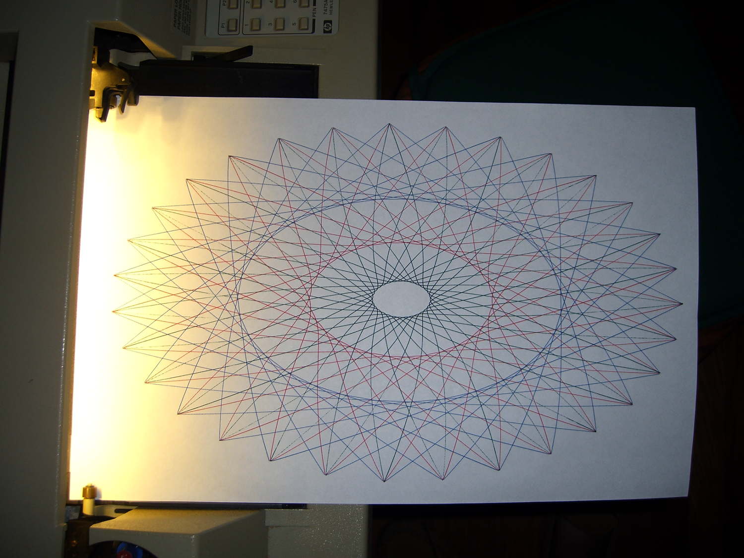
So, for example, with m=3.1, setting n1= 0.15, 0.30, 0.60 produces this pattern with 31 points:
HP 7475A – Superformula – m 3.1 vary n1
Varying both at once, thusly: (m,n1) = (1.9,0.20)=green (3.7,0.30)=red (4.9,0.40)=blue
produces this pattern:
HP 7475A – Superformula – m 1.9 3.7 4.9 n1 0.2 0.3 0.4
Yeah, 49 isn’t a prime number. It’s interesting, though.
Note that n1 doesn’t set the absolute location of the innermost points; you must see how it interacts with m before leaping to any conclusions.
It’s still not much in the way of Art, but it does keep the plotter chugging along for quite a while and that’s the whole point. I must yank the functions out of the Chiplotle library, set my default values, add one point to automagically close the last vertex, and maybe convert them to polar coordinates to adjust the magnitude as a function of angle.
Yes, that poor green ceramic-tip pen is running out of ink after all these decades.
Given the ionization chamber’s tiny currents and the huge resistors required to turn them into voltages, reviewing the thermal noise I generally ignore seems in order…
The RMS noise voltage of an ordinary resistor:
vn = √ (4 kB T R Δf)
The constants:
kB – Boltzman’s Constant = 1.38×10⁻²³ J/K
T – temperature in kelvin = 300 K (close enough)
Mashing them together:
vn = √ (16.6x10⁻²¹ R Δf)
vn = 129x10-12 √ (R Δf)
For a (generous) pulse current of 20 fA, a 10 GΩ resistor produces a mere 200 μV, so wrap a gain of 100 around the op amp to get 20 mV. An LMC6081 has a GBW just over 1 MHz, giving a 10 kHz bandwidth:
vn = 129x10-12 √ (10x109 10x103) = 1.3 mV
Which says the noise will be loud, but not deafening.
A 100 GΩ resistor increases the voltage by a factor of 10, so you can decrease the gain by a factor of ten for the same 20 mV output, which increases the bandwidth by a factor of ten, which increases the noise by a factor of … ten.
Ouch.
With the same gain of 100 (and therefore 10 kHz bandwidth) after the 100 GΩ resistor, the output increases by a factor of ten to 200 mV, but the noise increases by only √10 to 4 mV.
The LMC6081 has 22 nV/√Hz and 0.2 fA/√Hz input-referred noise, neither of which will rise above the grass from the resistor.
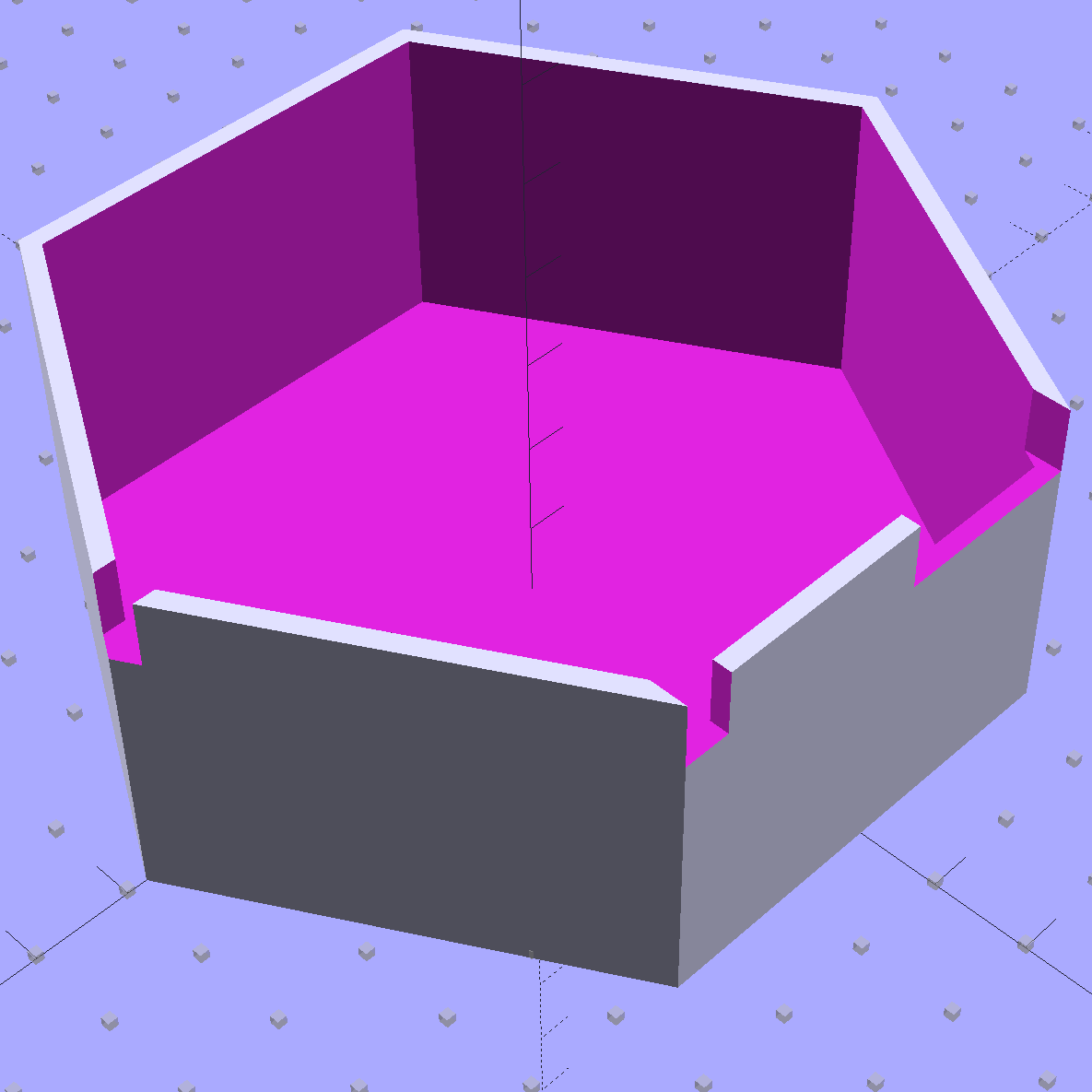
Lining the shield support box with copper foil tape turned out to be surprisingly easy:
Electrometer amp – shield – end view
The flat surface is two overlapping strips of 2 inch wide copper tape. I traced the exterior of the support box on the tape, cut neatly along the lines, slit the corners, bent the edges upward, peeled off the backing paper, stuck the tape into the box, pressed the edges into the corners, and didn’t cut myself once.
Applying 1 inch wide tape to the wall went just as smoothly, after I realized that I should cut it into strips just slightly longer than the hexagon’s sides.
The tape along the rim is adhesive copper mesh that’s springy enough to make contact all around the edge. I cut the 1 inch wide tape in half, which was just barely wide enough to reach::
Electrometer amp – shield – mesh soldering
Although you’re supposed to join the entire length of each seam for best RF-proofing, I tacked the corners and the middle of the long edge, then hoped for the best. The copper mesh seems to be plated on plastic threads that requires a fast hand to solder without melting, but I’m getting better at it. The adhesive is said to be conductive, but I loves me some good solder blob action.
The resistance from the flat bottom to the side panels and the fabric on the edge started out at a few ohms before soldering and dropped to 0.0 Ω after soldering, so I’ll call it a success. Didn’t even melt the outside of the PETG box, but I admit I didn’t take it apart to see what the copper-to-PETG surface looks like.
Covering the foil on the sides with 1 inch Kapton tape completed the decoration. I didn’t bother to cover the flat surface, because none of the circuitry should reach that far, and didn’t worry about covering the fabric tape for similar reasons. As madbodger pointed out, this violates the no-plastic-on-the-inside rule, but I’m still hoping for better results than having the entire plastic structure with all its charges on the inside.
A strip of horribly clashing orange plastic tape (which might be splicing tape for reel-to-reel recording tape) covers the outside edges of the fabric, prevents fraying, and gives the black electrical tape that holds the box down a solid grip:
Electrometer amp – shield – exterior
Yeah, like you’d notice mismatched colors around here.
Using black tape as an anchor seemed easier and better than messing with nesting pins & sockets. The copper fabric tape makes good contact with the rim of the PCB all the way around the perimeter and the black tape holds it firmly in place.
Early reports suggest the shield works pretty well…
Although I’d thought of a Mu-metal shield, copper foil tape should be easier and safer to shape into a simple shield. The general idea is to line the interior with copper tape, solder the joints together, cover with Kapton tape to reduce the likelihood of shorts, then stick it in place with some connector pin-and-socket combinations. Putting the tape on the outside would be much easier, but that would surround the circuitry with a layer of plastic that probably carries enough charge to throw things off.
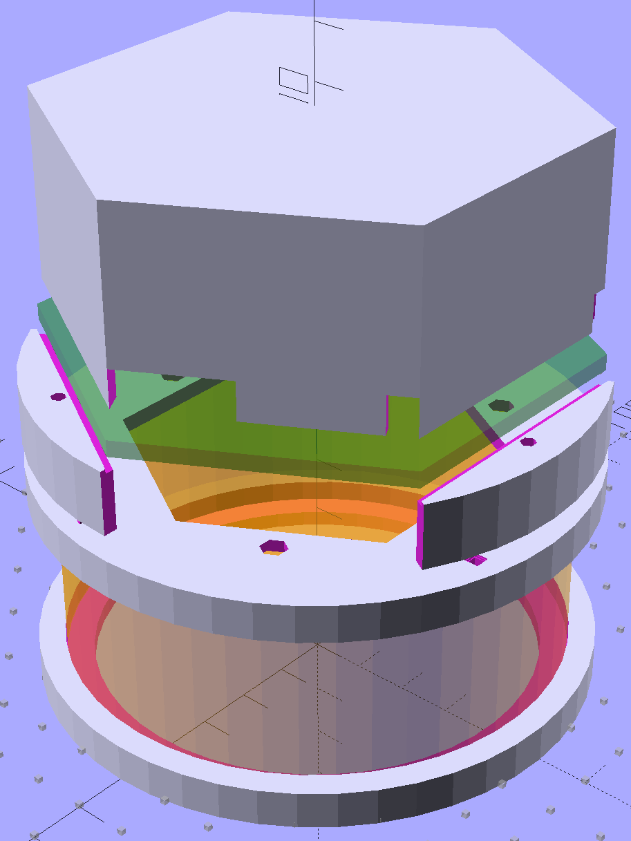
Anyhow, the hexagonal circuit board model now sports a hexagonal cap to support the shield:
Victoreen 710-104 Ionization Chamber Fittings – Show with shield
The ad-hoc openings fit various switches, wires, & twiddlepots: