In the unlikely event our bikes need two running lights or, perhaps, a running light and a headlight, the solid model now builds mounts for the right side of the fairing, as before:
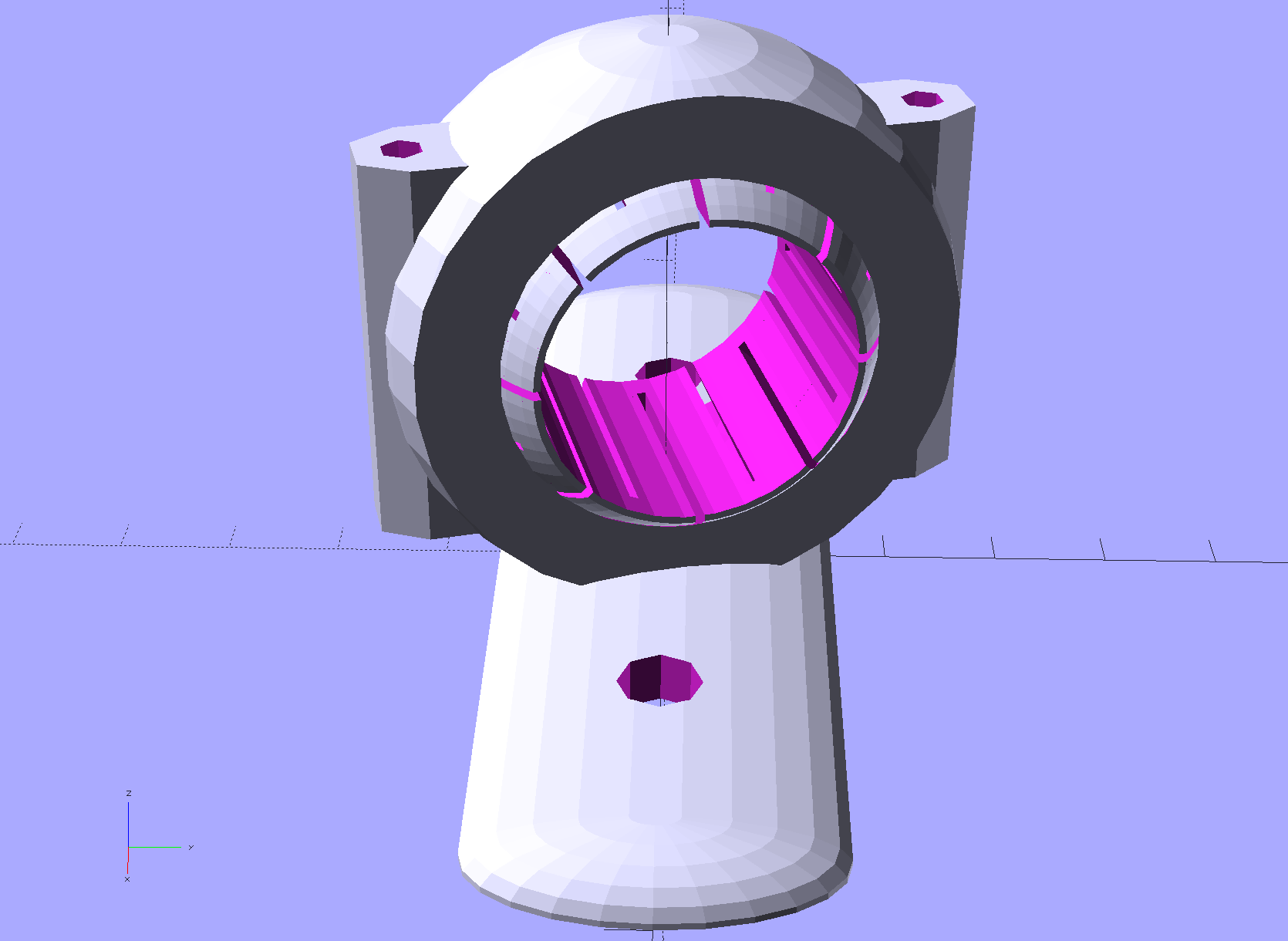
And for the left side:

Ahhh, chirality: love that word.
Those pix come from a cleaned-up version of the OpenSCAD code that finally gets the 3-axis rotations right, after a rip-and-replace rewrite to deliver the ball model with its origin in the center of the ball where it belonged and rotate the ring about its geometric center. Then the rotations become trivially easy and a slight hack job spits out a completely assembled model:
if (Component == "Complete") {
  translate([-BracketHoleOC,0,0])
    PlateBlank();
  mirror(TiltMirror) {
    translate([0,0,ClampOD/2]) {
      rotate([-Roll,ToeIn,Tilt])
        SlotBall();
      rotate([-Roll,ToeIn,Tilt])
        BallClamp();
    }
  }
}
However, putting the center of rotation directly over the center of the base plate means the ToeIn rotation shifts the bottom of the clamp ring along the X axis, where it can obstruct the mounting holes. Shifting the ring by a little bit:
ClampOD*sin(ToeIn/2)
… keeps the ring more-or-less centered on the top of the plate. That’s not quite the correct geometry, but it’s close enough for the small angles needed here.
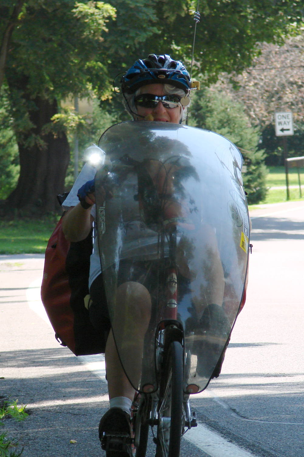
Aiming the beam slightly higher makes a 400 lumen flashlight about as bright as any single LED in new car running lights:
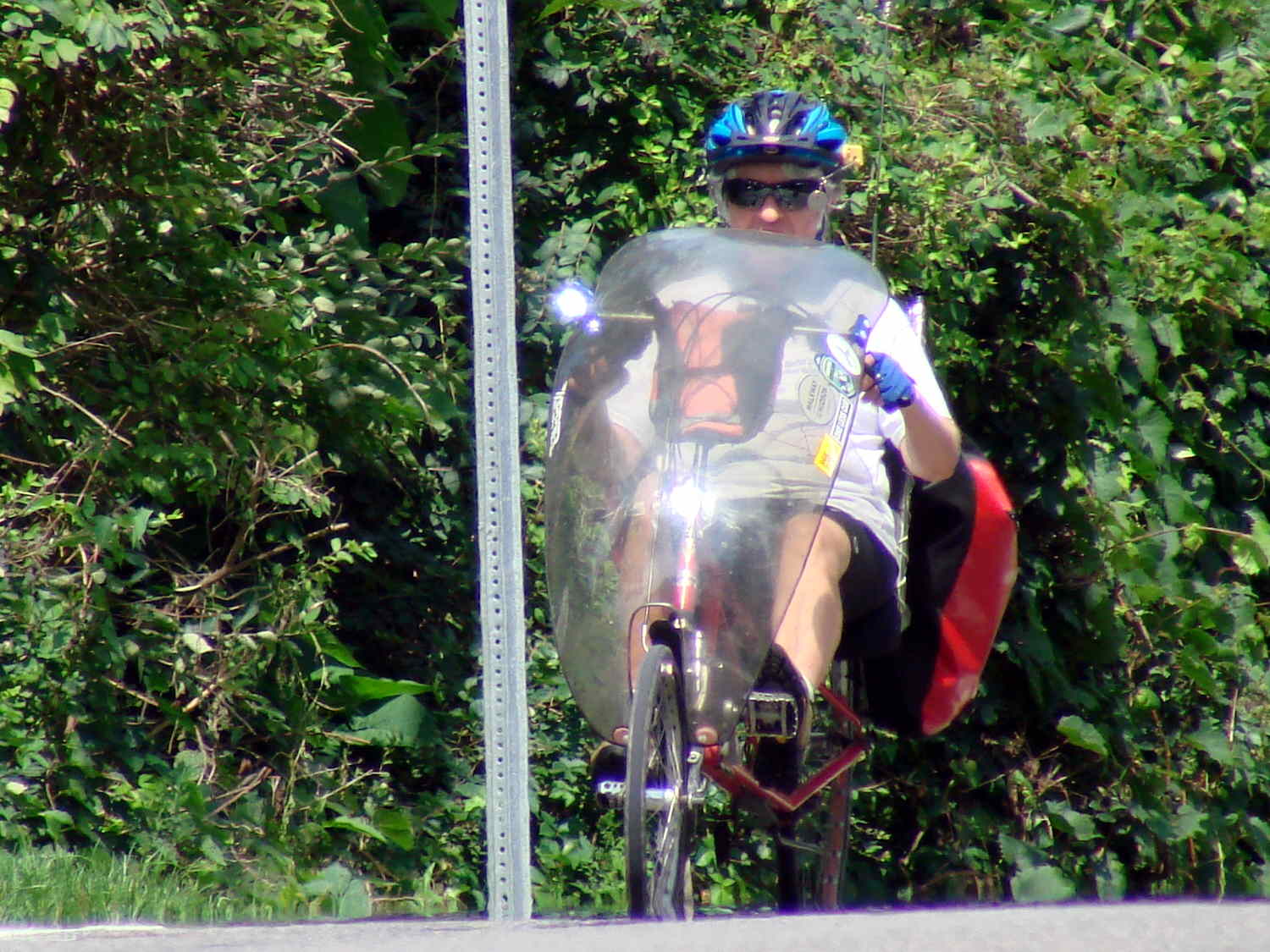
You can just barely make out the snazzy new blue plate on the left side of the fairing.
A bike’s natural back-and-forth handlebar motion sweeps the beam across the lane, so I think there’s no real benefit from blinking.
The OpenSCAD source code as a GitHub Gist:
| // Tour Easy Fairing Flashlight Mount | |
| // Ed Nisley KE4ZNU – July 2017 | |
| // August 2017 – | |
| /* [Build Options] */ | |
| FlashName = "AnkerLC40"; // [AnkerLC40,AnkerLC90,J5TactV2,InnovaX5] | |
| Component = "Complete"; // [Ball, BallClamp, Mount, Plates, Bracket, Complete] | |
| Layout = "Show"; // [Build, Show] | |
| Support = false; | |
| MountSupport = false; | |
| /* [Extrusion] */ | |
| ThreadThick = 0.25; // [0.20, 0.25] | |
| ThreadWidth = 0.40; // [0.40] | |
| function IntegerMultiple(Size,Unit) = Unit * ceil(Size / Unit); | |
| Protrusion = 0.01; // [0.01, 0.1] | |
| HoleWindage = 0.2; | |
| /* [Fairing Mount] */ | |
| Side = "Right"; // [Right,Left] | |
| ToeIn = 0; // inward from ahead | |
| Tilt = 15; // upward from forward (M=20 E=15) | |
| Roll = 0; // outward from top | |
| //- Screws *c | |
| /* [Hidden] */ | |
| ID = 0; | |
| OD = 1; | |
| LENGTH = 2; | |
| /* [Screws and Inserts] */ | |
| ClampInsert = [3.0,4.2,8.0]; | |
| ClampScrew = [3.0,5.9,35.0]; // thread dia, head OD, screw length | |
| ClampScrewWasher = [3.0,6.75,0.5]; | |
| ClampScrewNut = [3.0,6.1,4.0]; // nyloc nut | |
| /* [Hidden] */ | |
| F_NAME = 0; | |
| F_GRIPOD = 1; | |
| F_GRIPLEN = 2; | |
| LightBodies = [ | |
| ["AnkerLC90",26.6,48.0], | |
| ["AnkerLC40",26.6,55.0], | |
| ["J5TactV2",25.0,30.0], | |
| ["InnovaX5",22.0,55.0] | |
| ]; | |
| //- Fairing Bracket | |
| // Magic numbers taken from the actual fairing mount | |
| /* [Hidden] */ | |
| inch = 25.4; | |
| BracketHoleOD = 0.25 * inch; // 1/4-20 bolt holes | |
| BracketHoleOC = 1.0 * inch; // fairing hole spacing | |
| // usually 1 inch, but 15/16 on one fairing | |
| Bracket = [48.0,16.3,3.6 – 0.6]; // fairing bracket end plate overall size | |
| BracketHoleOffset = (3/8) * inch; // end to hole center | |
| BracketM = 3.0; // endcap arc height | |
| BracketR = (pow(BracketM,2) + pow(Bracket[1],2)/4) / (2*BracketM); // … radius | |
| //- Base plate dimensions | |
| Plate = [100.0,30.0,6*ThreadThick + Bracket[2]]; | |
| PlateRad = Plate[1]/4; | |
| RoundEnds = true; | |
| echo(str("Base plate thick: ",Plate[2])); | |
| //- Select flashlight data from table | |
| echo(str("Flashlight: ",FlashName)); | |
| FlashIndex = search([FlashName],LightBodies,1,0)[F_NAME]; | |
| //- Set ball dimensions | |
| BallWall = 5.0; // max ball wall thickness | |
| echo(str("Ball wall: ",BallWall)); | |
| BallOD = IntegerMultiple(LightBodies[FlashIndex][F_GRIPOD] + 2*BallWall,1.0); | |
| echo(str(" OD: ",BallOD)); | |
| BallLength = IntegerMultiple(min(sqrt(pow(BallOD,2) – pow(LightBodies[FlashIndex][F_GRIPOD],2)) – 2*4*ThreadThick, | |
| LightBodies[FlashIndex][F_GRIPLEN]),1.0); | |
| echo(str(" length: ",BallLength)); | |
| BallSides = 8*4; | |
| //- Set clamp ring dimensions | |
| ClampOD = 50; | |
| echo(str("Clamp OD: ",ClampOD)); | |
| ClampLength = min(20.0,0.75*BallLength); | |
| echo(str(" length: ",ClampLength)); | |
| ClampScrewOC = IntegerMultiple((ClampOD + BallOD)/2,1); | |
| echo(str(" screw OC: ",ClampScrewOC)); | |
| TiltMirror = (Side == "Right") ? [0,0,0] : [0,1,0]; | |
| //- Adjust hole diameter to make the size come out right | |
| module PolyCyl(Dia,Height,ForceSides=0) { // based on nophead's polyholes | |
| Sides = (ForceSides != 0) ? ForceSides : (ceil(Dia) + 2); | |
| FixDia = Dia / cos(180/Sides); | |
| cylinder(r=(FixDia + HoleWindage)/2,h=Height,$fn=Sides); | |
| } | |
| //- Fairing Bracket | |
| // This part of the fairing mount supports the whole flashlight mount | |
| // Centered on screw hole | |
| module Bracket() { | |
| linear_extrude(height=Bracket[2],convexity=2) | |
| difference() { | |
| translate([(Bracket[0]/2 – BracketHoleOffset),0,0]) | |
| offset(delta=ThreadWidth) | |
| intersection() { | |
| square([Bracket[0],Bracket[1]],center=true); | |
| union() { | |
| for (i=[-1,0,1]) // middle circle fills gap | |
| translate([i*(Bracket[0]/2 – BracketR),0]) | |
| circle(r=BracketR); | |
| } | |
| } | |
| circle(d=BracketHoleOD/cos(180/8),$fn=8); // dead center at the origin | |
| } | |
| } | |
| //- General plate shape | |
| // Centered on the hole for the fairing bracket | |
| module PlateBlank() { | |
| difference() { | |
| translate([BracketHoleOC,0,0]) | |
| intersection() { | |
| translate([0,0,Plate[2]/2]) // select upper half of spheres | |
| cube(Plate,center=true); | |
| hull() | |
| if (RoundEnds) | |
| for (i=[-1,1]) | |
| translate([i*(Plate[0]/2 – PlateRad),0,0]) | |
| resize([Plate[1]/2,Plate[1],2*Plate[2]]) | |
| sphere(r=PlateRad); // nice round ends! | |
| else | |
| for (i=[-1,1], j=[-1,1]) | |
| translate([i*(Plate[0]/2 – PlateRad),j*(Plate[1]/2 – PlateRad),0]) | |
| resize([2*PlateRad,2*PlateRad,2*Plate[2]]) | |
| sphere(r=PlateRad); // nice round corners! | |
| } | |
| translate([2*BracketHoleOC,0,-Protrusion]) // punch screw holes | |
| PolyCyl(BracketHoleOD,2*Plate[2],8); | |
| translate([0,0,-Protrusion]) | |
| PolyCyl(BracketHoleOD,2*Plate[2],8); | |
| } | |
| } | |
| //- Inner plate | |
| module InnerPlate() { | |
| difference() { | |
| PlateBlank(); | |
| translate([0,0,Plate[2] – Bracket[2] + Protrusion]) // punch fairing bracket | |
| Bracket(); | |
| } | |
| } | |
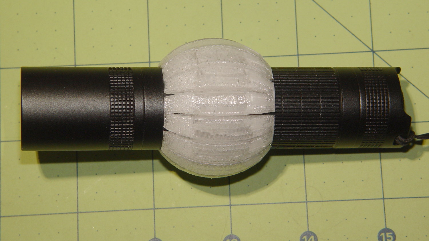
| //- Slotted ball around flashlight | |
| // Print with brim to ensure adhesion! | |
| module SlotBall() { | |
| NumSlots = 8*2; // must be even, half cut from each end | |
| SlotWidth = 2*ThreadWidth; | |
| SlotBaseThick = 10*ThreadThick; // enough to hold finger ends together | |
| RibLength = (BallOD – LightBodies[FlashIndex][F_GRIPOD])/2; | |
| translate([0,0,(Layout == "Build") ? BallLength/2 : 0]) | |
| rotate([0,(Layout == "Show") ? 90 : 0,0]) | |
| difference() { | |
| intersection() { | |
| sphere(d=BallOD,$fn=2*BallSides); // basic ball | |
| cube([2*BallOD,2*BallOD,BallLength],center=true); // trim to length | |
| } | |
| translate([0,0,-LightBodies[FlashIndex][F_GRIPOD]]) | |
| rotate(180/BallSides) | |
| PolyCyl(LightBodies[FlashIndex][F_GRIPOD],2*BallOD,BallSides); // remove flashlight body | |
| for (i=[0:NumSlots/2 – 1]) { // cut slots | |
| a=i*(2*360/NumSlots); | |
| SlotCutterLength = LightBodies[FlashIndex][F_GRIPOD]; | |
| rotate(a) | |
| translate([SlotCutterLength/2,0,SlotBaseThick]) | |
| cube([SlotCutterLength,SlotWidth,BallLength],center=true); | |
| rotate(a + 360/NumSlots) | |
| translate([SlotCutterLength/2,0,-SlotBaseThick]) | |
| cube([SlotCutterLength,SlotWidth,BallLength],center=true); | |
| } | |
| } | |
| color("Yellow") | |
| if (Support && (Layout == "Build")) { | |
| for (i=[0:NumSlots-1]) { | |
| a = i*360/NumSlots; | |
| rotate(a + 180/NumSlots) | |
| translate([(LightBodies[FlashIndex][F_GRIPOD] + RibLength)/2 + ThreadWidth,0,BallLength/(2*4)]) | |
| cube([RibLength,2*ThreadWidth,BallLength/4],center=true); | |
| } | |
| } | |
| } | |
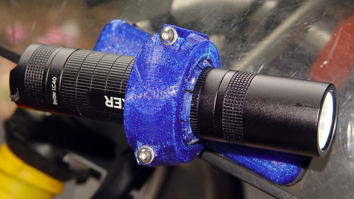
| //- Clamp around flashlight ball | |
| module BallClamp(Section="All") { | |
| BossLength = ClampScrew[LENGTH] – 1*ClampScrewWasher[LENGTH]; | |
| BossOD = ClampInsert[OD] + 2*(6*ThreadWidth); | |
| difference() { | |
| union() { | |
| intersection() { | |
| sphere(d=ClampOD,$fn=BallSides); // exterior ball clamp | |
| cube([ClampLength,2*ClampOD,2*ClampOD],center=true); // aiming allowance | |
| } | |
| hull() | |
| for (j=[-1,1]) | |
| translate([0,j*ClampScrewOC/2,-BossLength/2]) | |
| cylinder(d=BossOD,h=BossLength,$fn=6); | |
| } | |
| sphere(d=(BallOD + 1*ThreadThick),$fn=BallSides); // interior ball with minimal clearance | |
| for (j=[-1,1]) { | |
| translate([0,j*ClampScrewOC/2,-ClampOD]) // screw clearance | |
| PolyCyl(ClampScrew[ID],2*ClampOD,6); | |
| translate([0,j*ClampScrewOC/2, // insert clearance | |
| -(BossLength/2 – ClampInsert[LENGTH] – 3*ThreadThick)]) | |
| rotate([0,180,0]) | |
| PolyCyl(ClampInsert[OD],2*ClampOD,6); | |
| translate([0,j*ClampScrewOC/2, // insert transition | |
| -(BossLength/2 – ClampInsert[LENGTH] – 3*ThreadThick)]) | |
| cylinder(d1=ClampInsert[OD]/cos(180/6),d2=ClampScrew[ID],h=6*ThreadThick,$fn=6); | |
| } | |
| if (Section == "Top") | |
| translate([0,0,-ClampOD/2]) | |
| cube([2*ClampOD,2*ClampOD,ClampOD],center=true); | |
| else if (Section == "Bottom") | |
| translate([0,0,ClampOD/2]) | |
| cube([2*ClampOD,2*ClampOD,ClampOD],center=true); | |
| } | |
| color("Yellow") | |
| if (Support) { // ad-hoc supports | |
| NumRibs = 6; | |
| RibLength = 0.5 * BallOD; | |
| RibWidth = 1.9*ThreadWidth; | |
| SupportOC = ClampLength / NumRibs; | |
| if (Section == "Top") // base plate for adhesion | |
| translate([0,0,ThreadThick]) | |
| cube([ClampLength + 6*ThreadWidth,RibLength,2*ThreadThick],center=true); | |
| else if (Section == "Bottom") | |
| translate([0,0,-ThreadThick]) | |
| cube([ClampLength + 6*ThreadWidth,RibLength,2*ThreadThick],center=true); | |
| render(convexity=2*NumRibs) | |
| intersection() { | |
| sphere(d=BallOD – 0*ThreadWidth); // cut at inner sphere OD | |
| cube([ClampLength + 2*ThreadWidth,RibLength,BallOD],center=true); | |
| if (Section == "Top") // select only desired section | |
| translate([0,0,ClampOD/2]) | |
| cube([2*ClampOD,2*ClampOD,ClampOD],center=true); | |
| else if (Section == "Bottom") | |
| translate([0,0,-ClampOD/2]) | |
| cube([2*ClampOD,2*ClampOD,ClampOD],center=true); | |
| union() { // ribs for E-Z build | |
| for (j=[-1,0,1]) | |
| translate([0,j*SupportOC,0]) | |
| cube([ClampLength,RibWidth,1.0*BallOD],center=true); | |
| for (i=[0:NumRibs]) // allow NumRibs + 1 to fill the far end | |
| translate([i*SupportOC – ClampLength/2,0,0]) | |
| rotate([0,90,0]) | |
| cylinder(d=BallOD – 2*ThreadThick, | |
| h=RibWidth,$fn=BallSides,center=true); | |
| } | |
| } | |
| } | |
| } | |
| //- Mount between fairing plate and flashlight ball | |
| // Build with support for bottom of clamp screws! | |
| module Mount() { | |
| TextRotate = (Side == "Right") ? 0 : 180; | |
| MountShift = [ClampOD*sin(ToeIn/2), | |
| 0, | |
| ClampOD/2]; | |
| difference() { | |
| translate([-BracketHoleOC,0,0]) // put bracket center at origin | |
| PlateBlank(); | |
| mirror([0,1,0]) | |
| translate([0,0,-Protrusion]) | |
| linear_extrude(height=3*ThreadThick + Protrusion) { | |
| translate([BracketHoleOC + 15,0,0]) | |
| text(text=">>>",size=5,spacing=1.20,font="Arial",halign="center",valign="center"); | |
| translate([-BracketHoleOC,8,0]) rotate(TextRotate) | |
| text(text=str("Toe ",ToeIn),size=5,spacing=1.20,font="Arial",halign="center",valign="center"); | |
| translate([-BracketHoleOC,-8,0]) rotate(TextRotate) | |
| text(text=str("Tilt ",Tilt),size=5,spacing=1.20,font="Arial",halign="center",valign="center"); | |
| translate([BracketHoleOC,-8,0]) rotate(TextRotate) | |
| text(text=Side,size=5,spacing=1.20,font="Arial",halign="center",valign="center"); | |
| translate([BracketHoleOC,8,0]) rotate(TextRotate) | |
| text(text=str("Roll ",Roll),size=5,spacing=1.20,font="Arial",halign="center",valign="center"); | |
| translate([-(BracketHoleOC + 15),0,0]) | |
| rotate(90) | |
| text(text="KE4ZNU",size=4,spacing=1.20,font="Arial",halign="center",valign="center"); | |
| } | |
| } | |
| mirror(TiltMirror) { | |
| translate(MountShift) | |
| rotate([-Roll,ToeIn,Tilt]) | |
| BallClamp("Bottom"); | |
| color("Yellow") | |
| if (MountSupport) { // anchor outer corners at worst overhang | |
| RibWidth = 1.9*ThreadWidth; | |
| SupportOC = 0.1 * ClampLength; | |
| difference() { | |
| rotate([0,0,Tilt]) | |
| translate([(ClampOD – BallOD)*sin(ToeIn/2),0,0]) | |
| for (i=[-4.5,-2.5,0,2.0,4.5]) | |
| translate([i*SupportOC – 0.0,0,(5 + Plate[2])/2]) | |
| cube([RibWidth,0.7*ClampOD,(5 + Plate[2])],center=true); | |
| translate(MountShift) | |
| rotate([-Roll,ToeIn,Tilt]) | |
| sphere(d=ClampOD – 2*ThreadWidth,$fn=BallSides); | |
| } | |
| } | |
| } | |
| } | |
| //- Build things | |
| if (Component == "Bracket") | |
| Bracket(); | |
| if (Component == "Ball") | |
| SlotBall(); | |
| if (Component == "BallClamp") | |
| if (Layout == "Show") | |
| BallClamp("All"); | |
| else if (Layout == "Build") | |
| BallClamp("Top"); | |
| if (Component == "Mount") | |
| Mount(); | |
| if (Component == "Plates") { | |
| translate([0,0.7*Plate[1],0]) | |
| InnerPlate(); | |
| translate([0,-0.7*Plate[1],0]) | |
| PlateBlank(); | |
| } | |
| if (Component == "Complete") { | |
| translate([-BracketHoleOC,0,0]) | |
| PlateBlank(); | |
| mirror(TiltMirror) { | |
| translate([0,0,ClampOD/2]) { | |
| rotate([-Roll,ToeIn,Tilt]) | |
| SlotBall(); | |
| rotate([-Roll,ToeIn,Tilt]) | |
| BallClamp(); | |
| } | |
| } | |
| } |