The rail height measurements suggested three shims could level the MPCNC rails:

The numbers inside the lower square give the additional height required to sorta-kinda level the result, keeping in mind we’re not dealing with a particularly stable mechanical setup.
The figures in the lower right translate sensible metric values into mils. I plucked those sheets from my brass shimstock selection, taped them together into a 42 mil stack, and introduced them to Mr Bandsaw:

The sacrificial sheet underneath the stack prevents bending. Using the saw (with a 24 tpi blade), rather than tin snips or scissors, produces a nice clean flat cut without any curling or bending.
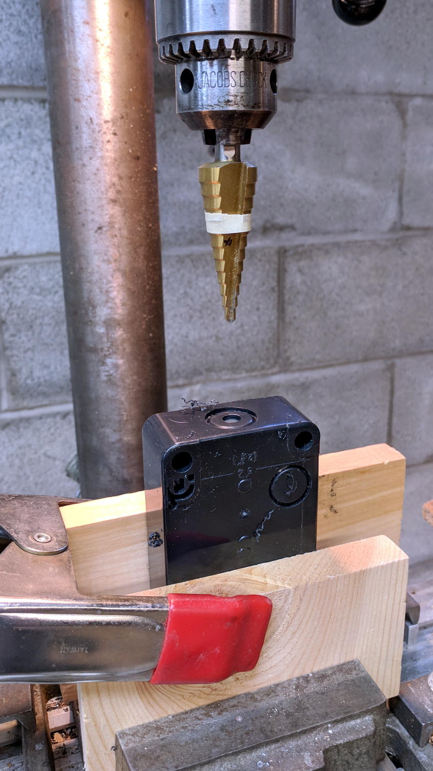
A brief conversation with Mr Drill Press created screw clearance holes:
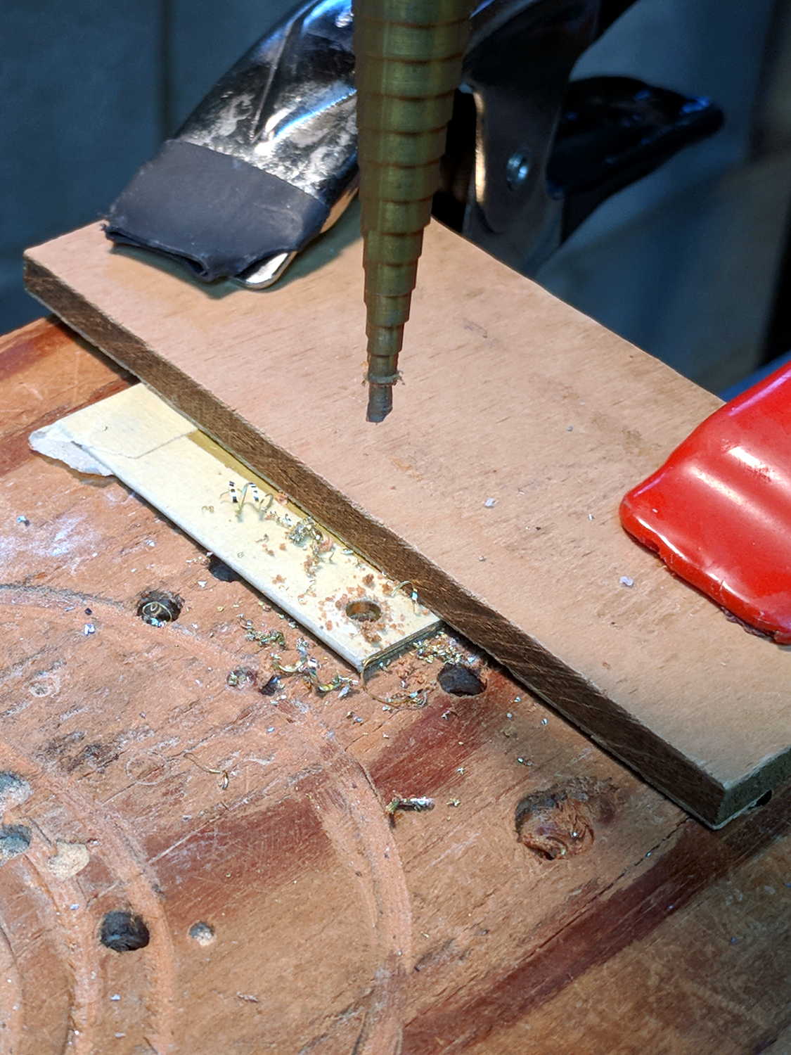
N.B.: Brass is fiercely grabby, so don’t use an ordinary twist drill. Blunt ’em if you have a spare set of drills, but a step drill works for my simple needs, shallow holes, and infrequent drilling. In any event, don’t hand-hold the sheets, because they can turn into whirling knives without the formality of warning you first.
I bandsawed the holes into slots, so I could slide the shims under the corner posts without completely removing the screws, in the hope the posts would stay more-or-less in the same place. Probably doesn’t make any difference:

Looks like I overtightened the post clamp screw a bit, doesn’t it? So it goes with 3D printed parts.
Another round of measurements with the shims in place:
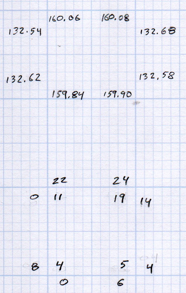
The numbers on the outside of the bottom set give the difference from the lowest rail in each direction, the inner numbers are the average of the two differences in each corner.
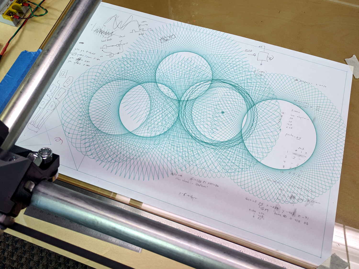
All of which seems to indicate the pen height now varies by a smidge over 0.1 mm across the span of those 16.5×14 inch plots.
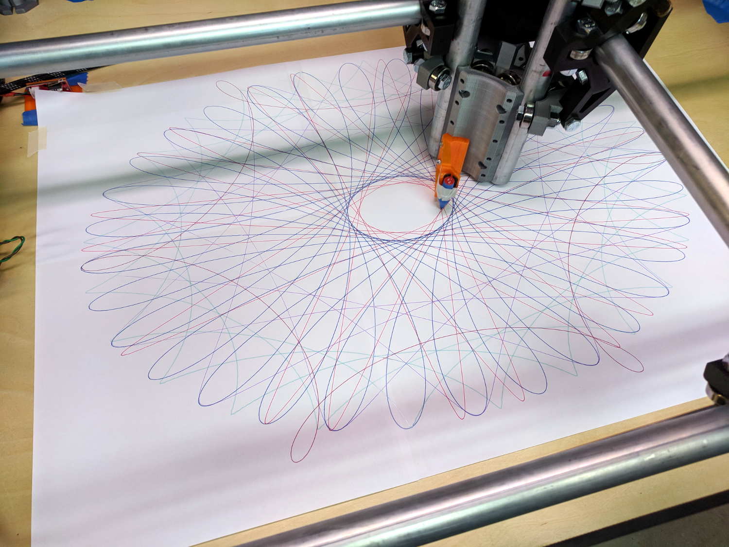
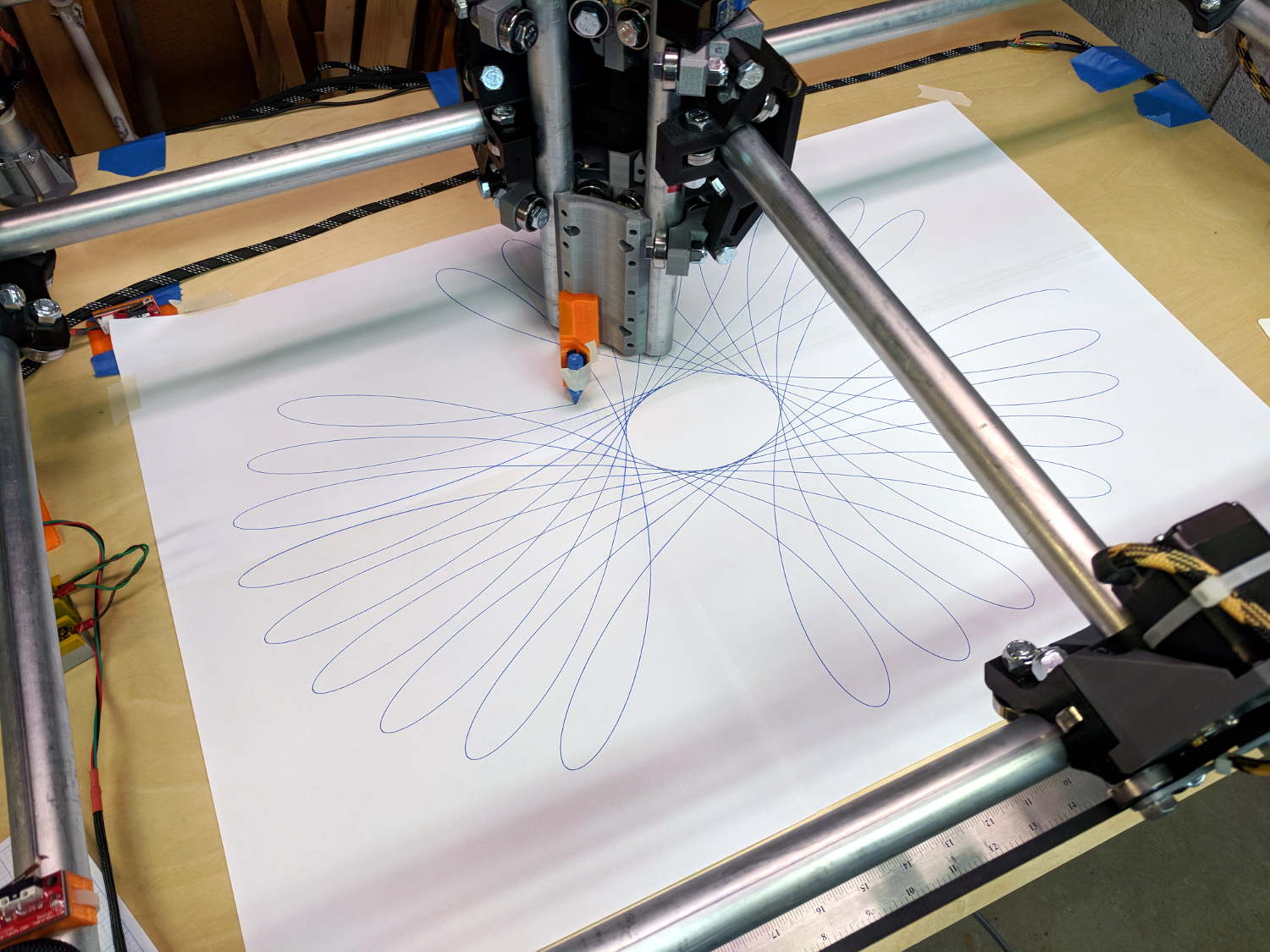
A plot with all the legends and traces at Z=-0.25 came out OK:
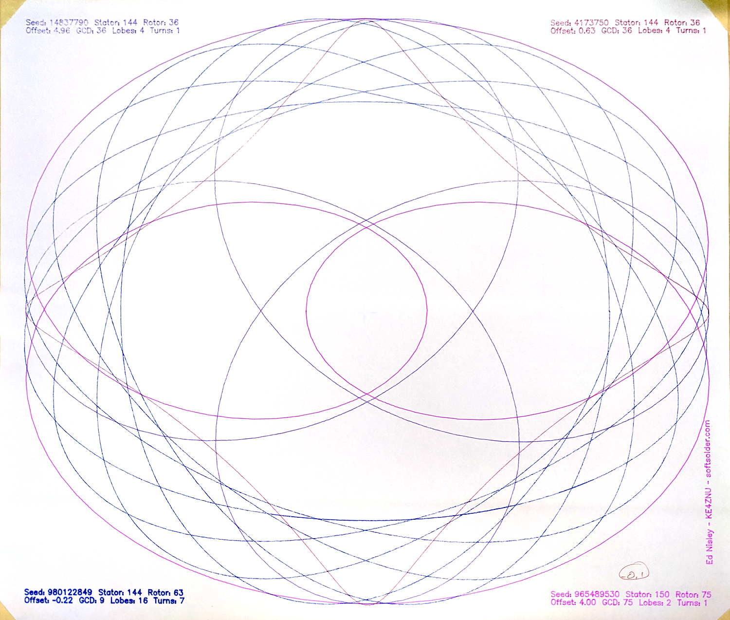
The legend in the upper left looked slightly faint:

The upper right legend looks about the same, suggesting my average of differences probably isn’t meaningful.
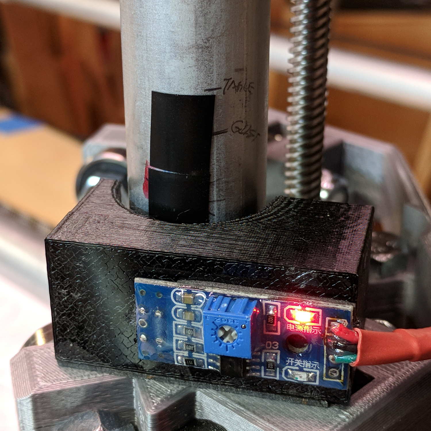
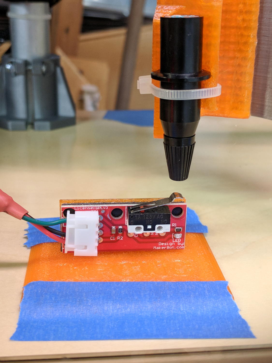
Lowering the pen to Z=-0.25 should darken the traces a bit and reduce the effect of any inconsistencies in the tool length probe switch.
Not, of course, that this will make much difference in actual use; a router will probably shake the whole thing out of alignment in a matter of seconds.