The Smell of Molten Projects in the Morning

Ed Nisley's Blog: Shop notes, electronics, firmware, machinery, 3D printing, laser cuttery, and curiosities. Contents: 100% human thinking, 0% AI slop.

Tag: Improvements

Making the world a better place, one piece at a time

  • Sena PS410 Serial Server: socat and minicom

    Per the socat man page:  “Socat … establishes two bidirectional byte streams and transfers data between them”. Using it to connect minicom to the HP Z3801 (PDF user manual) GPS receiver’s serial port on the PS410 serial server goes like this:

    socat pty,link=/tmp/z3801 tcp:192.168.1.40:7003 &
    

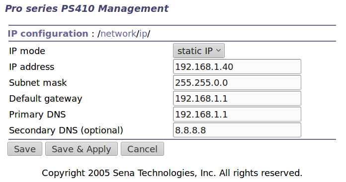
    The 7003 designates the network port corresponding to serial port 3 on the PS410. The PS410 lets you give its ports any numbers you like, but that way lies madness.

    You may want to run socat in a separate terminal window for easy monitoring (use -d -d for more details) and restarting. The PS410 closes all its network connections when updating any configuration values, pushing any ongoing conversations off the rails. Of course, one doesn’t update the configuration very often after getting it right.

    It produces a device with permissions just for you:

    lrwxrwxrwx 1 ed ed 10 Mar 17 18:45 z3801 -> /dev/pts/2
    

    Whereupon you aim minicom (or whatever you like) at the device:

    minicom -D /tmp/z3801
    

    And It Just Works.

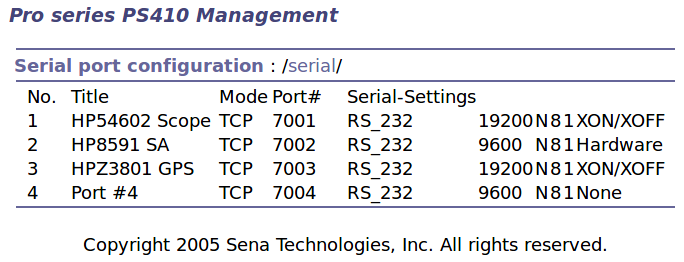
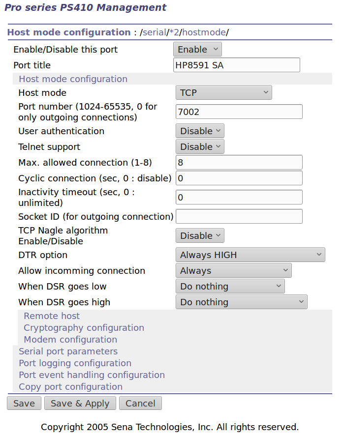
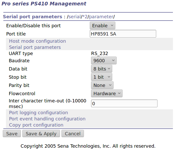
    The PS410 serial port configuration:

    Port 3 - Z3801 serial config
    Port 3 – Z3801 serial config

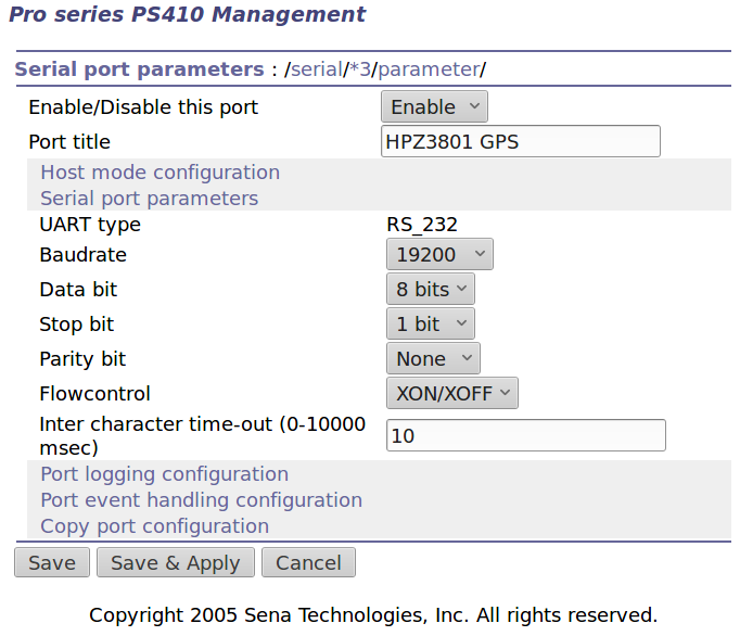
    The default Z3801 serial port setup seems to be 19200, 7 data, odd parity. I vaguely recall some serial port hackage a long time ago, with the details buried in my paper (!) notes.

    Leaving the Inter Character Timeout at the default 0 creates a blizzard of network activity. Setting it to 10 ms produces slight delays during the full-screen (on an 80 character x 24 line green screen monitor, anyway) status display:

    Z3801 system status
    Z3801 system status

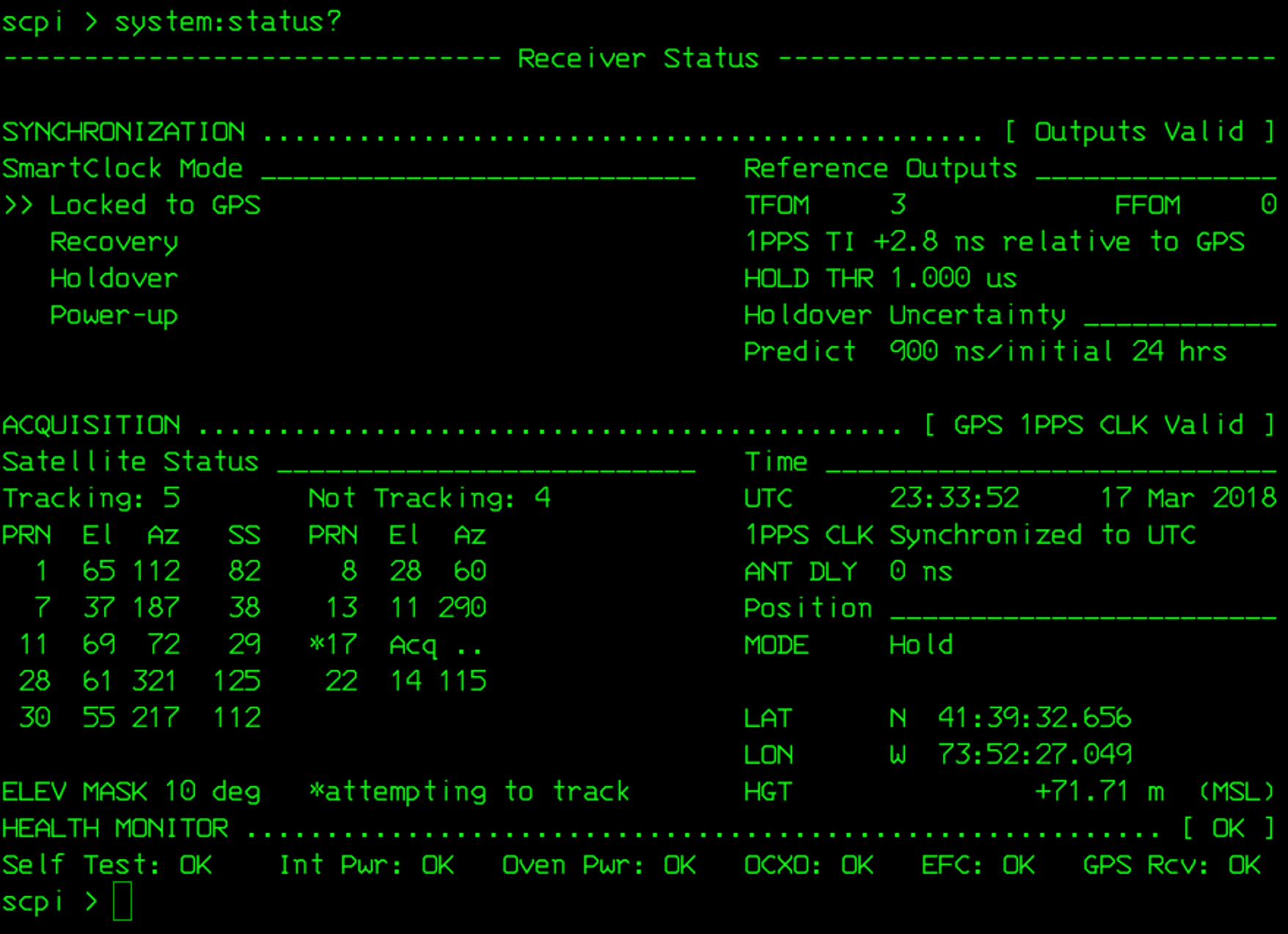
    I inadvertently turned off the UPS powering the thing and the double-oven clock oscillator takes days to restabilize; the Holdover Uncertainty has been dropping slowly ever since.

    Verily, it is written that a man with two clocks never knows what time it is. When one of them is a Z3801, the man has no doubt which clock is correct.

  • MPCNC: USB Camera Alignment

    Adding a lock screw to the camera mount stabilized the camera-to-spindle offset enough to make calibration meaningful. Mark the spot directly under the camera:

    bCNC - Camera - hot glue align
    bCNC – Camera – hot glue align

    Then mark the spot directly under the spindle, perhaps by poking a small cutter into the tape, measure the XY distances between the two center points, and use bCNC’s camera registration process to set the camera offset.

    With those numbers in place, switching to the tool view (the green button with the end mill to the right in the ribbon bar) puts the camera at the spindle location:

    bCNC - Spindle - hot glue align
    bCNC – Spindle – hot glue align

    The view from outside shows the relation between those two pieces of tape:

    MPCNC - USB camera-to-spindle alignment
    MPCNC – USB camera-to-spindle alignment

    Now I can align the camera view to a fixture position and be (reasonably) sure the spindle will automagically align to the same XY coordinate when I switch to the “tool” view. Seems to work well in preliminary tests, anyhow.

  • MPCNC: USB Camera Mount With Lock Screw

    It turned out the previous version of the USB camera mount lacked sufficient griptivity to hold the ball’s position against even moderate bumps, so the upper “half” is now tall enough to hold a lock screw directly over the ball:

    MPCNC - USB Camera mount - lock screw - Slic3r
    MPCNC – USB Camera mount – lock screw – Slic3r

    It doesn’t look much different:

    MPCNC - USB Camera Mount - lock screw
    MPCNC – USB Camera Mount – lock screw

    A view from the other side:

    USB Camera - lock screw mount
    USB Camera – lock screw mount

    The previous iterations used Genuine 3M foam tape, which seemed too flexy for comfort. This one sits on a bed of hot melt glue and is absolutely rigid. We’ll see how long it survives.

    Tightening the cap screw requires needle-nose pliers, because the whole affair has no room for a hex key.

    The OpenSCAD source code as a GitHub Gist:

    // MPCNC USB Camera Mount
    // Ed Nisley KE4ZNU – 2018-02-22
    Layout = "Build"; // Build, Show
    /* [Extrusion] */
    ThreadThick = 0.25; // [0.20, 0.25]
    ThreadWidth = 0.40; // [0.40]
    /* [Hidden] */
    Protrusion = 0.1; // [0.01, 0.1]
    HoleWindage = 0.2;
    inch = 25.4;
    function IntegerMultiple(Size,Unit) = Unit * ceil(Size / Unit);
    ID = 0;
    OD = 1;
    LENGTH = 2;
    //- Adjust hole diameter to make the size come out right
    module PolyCyl(Dia,Height,ForceSides=0) { // based on nophead's polyholes
    Sides = (ForceSides != 0) ? ForceSides : (ceil(Dia) + 2);
    FixDia = Dia / cos(180/Sides);
    cylinder(r=(FixDia + HoleWindage)/2,h=Height,$fn=Sides);
    }
    //- Dimensions
    WallThick = 3.0; // minimum thickness / width
    CameraStalk = [6.0 + 1.0,10.0 + HoleWindage,4.0]; // stalk OD, ball OD, stalk length
    CameraAngle = -5; // stalk tilt, negative = downward
    Screw = [3.0,7.0,25.0]; // holding it all together, OD = washer
    Insert = [3.0,4.4,4.5]; // brass insert
    Pusher = Insert[LENGTH] / 2; // plastic locking snippet
    UpperThick = IntegerMultiple(CameraStalk[OD]/2 + Insert[LENGTH] + Pusher + WallThick,ThreadThick);
    LowerThick = Screw[LENGTH] – UpperThick;
    MountBlock = [24.0,20.0,LowerThick + UpperThick];
    echo(str("Block: ",MountBlock));
    NumSides = 6*4;
    //—–
    // Define shapes
    // Camera mount, enlongated for E-Z differencing
    // Origin at center of ball, stalk along +X
    module Camera() {
    union() {
    sphere(d=CameraStalk[OD],$fn=NumSides);
    rotate([0,90 – CameraAngle,0])
    PolyCyl(CameraStalk[ID],3*CameraStalk[LENGTH],NumSides);
    }
    }
    // Mount block with all the cutouts
    // Ball centerline on XY plane = block split line
    module Mount(Half="All") {
    Rounding = 2.0; // corner radius
    ZShift = // block shift to remove unwanted half
    (Half == "Upper") ? -MountBlock.z/2 – 0*UpperThick :
    (Half == "Lower") ? MountBlock.z/2 + 0*LowerThick :
    2*MountBlock.z; // … want both halves, remove none
    difference() {
    hull()
    for (i=[-1,1], j=[-1,1]) {
    translate([i*(MountBlock.x/2 – Rounding),j*(MountBlock.y/2 – Rounding),(UpperThick – Rounding)])
    sphere(r=Rounding,$fn=3*4);
    translate([i*(MountBlock.x/2 – Rounding),j*(MountBlock.y/2 – Rounding),-(LowerThick – Rounding)])
    sphere(r=Rounding,$fn=3*4);
    }
    for (j=[-1,1])
    translate([-MountBlock.x/4,j*MountBlock.y/4,-(LowerThick + Protrusion)]) {
    PolyCyl(Insert[OD],Insert[LENGTH] + Protrusion,6);
    PolyCyl(Insert[ID],2*MountBlock.z,6);
    }
    translate([MountBlock.x/2 – (CameraStalk[OD]/2 + CameraStalk[LENGTH]),0,0]) {
    Camera();
    translate([0,0,UpperThick – (Insert[LENGTH] + WallThick)])
    PolyCyl(Insert[OD],Insert[LENGTH] + WallThick,6);
    PolyCyl(Insert[ID],2*UpperThick,6);
    }
    translate([0,0,ZShift])
    cube([2*MountBlock.x,2*MountBlock.y,MountBlock.z],center=true);
    }
    }
    //—–
    // Build it
    if (Layout == "Show")
    Mount("All");
    if (Layout == "Build") {
    translate([0,0.75*MountBlock.y,UpperThick])
    rotate([180,0,0])
    Mount("Upper");
    translate([0,-0.75*MountBlock.y,LowerThick])
    rotate([0,0,0])
    Mount("Lower");}
  • Baofeng BL-5 Pack Rebuild

    The 18650 cell protection PCBs with 8205 ICs arrived and seemed small enough to simply tuck into the gap between the rounded cells in the second Baofeng BL-5 pack:

    Baofeng BL-5 - new protection PCB - wiring 1
    Baofeng BL-5 – new protection PCB – wiring 1

    For whatever it might be worth, you’re looking at the only Baofeng battery pack containing an actual 10 kΩ thermistor, harvested from the benchtop Tray of Doom:

    Baofeng BL-5 pack - thermistor
    Baofeng BL-5 pack – thermistor

    Unfortunately, the components on the PCB stuck up a bit too far from the cell surface and held the lid just slightly proud of the case. Applying pressure to lithium cells being a Bad Idea, I rearranged the layout by flipping the cells over, tucking the PCB components between the cells, and connecting everything with nickel tape instead of insulated wires:

    Baofeng BL-5 - new protection PCB - wiring 2
    Baofeng BL-5 – new protection PCB – wiring 2

    The snippets of manila paper and Kapton tape hold things apart and together, as needed. Looks ugly, fits better.

    Pop it in the charger to reset the protection PCB lockout and it’s all good again.

  • Sena PS410 Serial Server: Configuration

    Although I cannot explain why those ferrite beads lit up, it seems connecting the DE-9 shell to the serial device ground is an Extremely Bad Idea. I removed that wire from the HP 8591 spectrum analyzer cable and everything seems to work, so I’ll declare victory:

    Sena PS410 Serial Server - in action
    Sena PS410 Serial Server – in action

    Not shown: the tangle of cables tucked behind that tidy box. You can plug a serial terminal into the DE-9 connector, but it’s much easier to use the PS410’s web interface.

    It needs a static IP address to make it findable, although I also told the router to force the same address should it start up in DHCP mode:

    IP Configuration
    IP Configuration

    Yeah, Google DNS, if all else fails.

    The serial port overview:

    Serial port overview
    Serial port overview

    I’ll go into more detail in a while about individual device setups and the scripts slurping screen shots out of them, but giving each one a useful name is a Good Idea, even though it doesn’t appear anywhere else. I changed the default Inactivity Timeout for each port from the default 100 seconds to zero, thereby preventing the PS410 from closing the connection due to inactivity:

    Serial Port 2 - host params
    Serial Port 2 – host params

    The DTR and DSR defaults work out well; the other choices solve problems I don’t have. Indeed, the PS410 has a myriad configuration options best left in their Disabled state.

    The serial parameters for each port need tweaking to suit the hardware gadget on the other end of the cable:

    Serial Port 2 - serial params
    Serial Port 2 – serial params

    Flow Control applies between the PS410 and the gadget. You can choose:

    • Disabled
    • XON/XOFF – in-band characters
    • RTS/CTS – RS-232 hardware signals

    Somewhat to my surprise, It Just Worked despite my blundering.

  • Bottle Cap Rehabilitation

    Mary acquired this bottle a long time ago and has used it forever, so it has Historic Connotations and cannot be discarded. Alas, the cardboard-and-plastic seal in the cap finally disintegrated; I replaced it with various plastic foams and sheets, none of which worked.

    Finally, I found the cork sheet stash while looking for something else and cut out a disk:

    Rehabilitated bottle cap
    Rehabilitated bottle cap

    It works perfectly, of course, because cork.

    That was easy.

  • SJCAM M20 Camera: Dimensions

    The SJCAM M20 action camera came with a whole bunch of doodads:

    SJCAM M20 Accessories - Manual pg 25
    SJCAM M20 Accessories – Manual pg 25

    Including a waterproof case, some right-angle connectors, and a pipe clamp:

    M20 in waterproof case - Tour Easy seat
    M20 in waterproof case – Tour Easy seat

    The stack turns out to be about as flexy as one might imagine, definitely a Bad Thing for a bike-mounted camera, and a somewhat more rugged mount seems in order.

    A diagram from the M20 manual shows the parts:

    SJCAM M20 Overview - Manual pg 5
    SJCAM M20 Overview – Manual pg 5

    Some camera dimensions:

    • 40.2 mm wide + 0.5 mm for the Up/Down buttons
    • 21.8 mm thick + 1.0 mm cylindrical front curve + 1.0 mm rear screen
    • 50.0 mm tall + 4.0 mm cylindrical top curve + buttons
    • 21.7 mm OD × 6.0 mm long lens housing, 1.3 mm down from top center

    All the edges have neat chamfers or radius rounding on the order of a few millimeters.

    Applying the chord equation to the spans inside the rounding:

    • Front radius: 162.5 mm
    • Top radius: 42.5 mm

    The new batteries survive for a bit over an hour, not quite enough for our usual rides. Rather than conjure a fake battery pack connected to an external 18650 cell with a wire chewed through the case, the least awful way to go may involve a relatively small battery pack (with internal 18650 cells, of course) plugged into the USB port with a right-angle cable and a rigid mount holding both the camera and the pack to the seat frame.

    More pondering is in order.