Ed Nisley's Blog: Shop notes, electronics, firmware, machinery, 3D printing, laser cuttery, and curiosities. Contents: 100% human thinking, 0% AI slop.
Tag: Improvements
Making the world a better place, one piece at a time
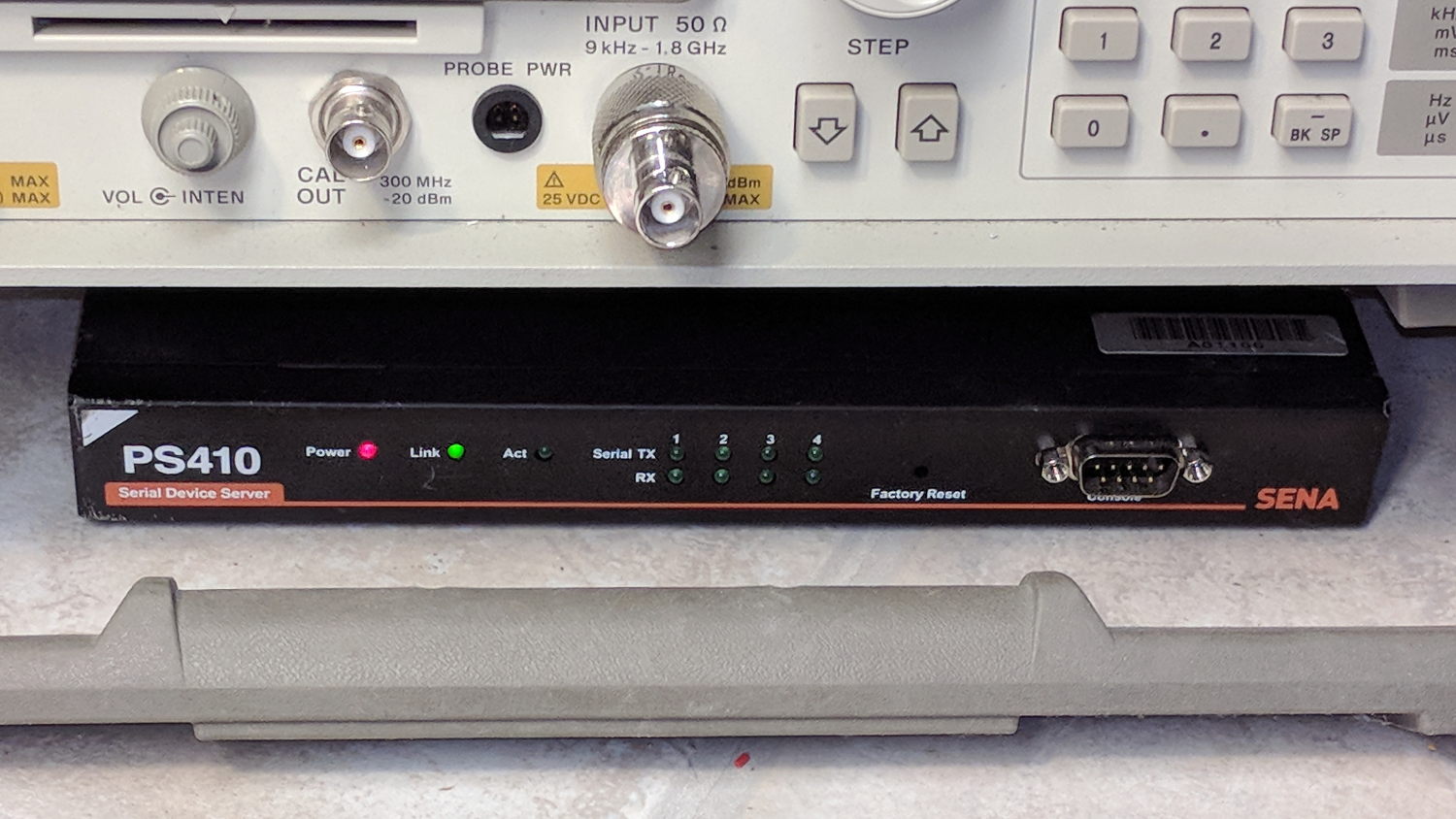
Although I cannot explain why those ferrite beads lit up, it seems connecting the DE-9 shell to the serial device ground is an Extremely Bad Idea. I removed that wire from the HP 8591 spectrum analyzer cable and everything seems to work, so I’ll declare victory:
Sena PS410 Serial Server – in action
Not shown: the tangle of cables tucked behind that tidy box. You can plug a serial terminal into the DE-9 connector, but it’s much easier to use the PS410’s web interface.
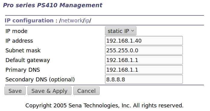
It needs a static IP address to make it findable, although I also told the router to force the same address should it start up in DHCP mode:
IP Configuration
Yeah, Google DNS, if all else fails.
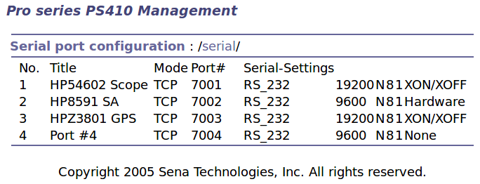
The serial port overview:
Serial port overview
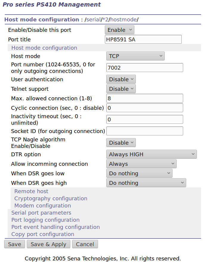
I’ll go into more detail in a while about individual device setups and the scripts slurping screen shots out of them, but giving each one a useful name is a Good Idea, even though it doesn’t appear anywhere else. I changed the default Inactivity Timeout for each port from the default 100 seconds to zero, thereby preventing the PS410 from closing the connection due to inactivity:
Serial Port 2 – host params
The DTR and DSR defaults work out well; the other choices solve problems I don’t have. Indeed, the PS410 has a myriad configuration options best left in their Disabled state.
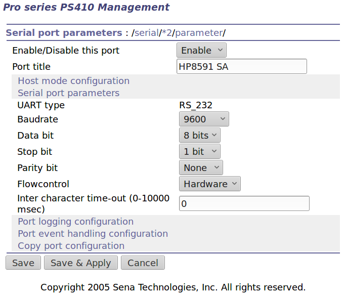
The serial parameters for each port need tweaking to suit the hardware gadget on the other end of the cable:
Serial Port 2 – serial params
Flow Control applies between the PS410 and the gadget. You can choose:
Disabled
XON/XOFF – in-band characters
RTS/CTS – RS-232 hardware signals
Somewhat to my surprise, It Just Worked despite my blundering.
Mary acquired this bottle a long time ago and has used it forever, so it has Historic Connotations and cannot be discarded. Alas, the cardboard-and-plastic seal in the cap finally disintegrated; I replaced it with various plastic foams and sheets, none of which worked.
Finally, I found the cork sheet stash while looking for something else and cut out a disk:
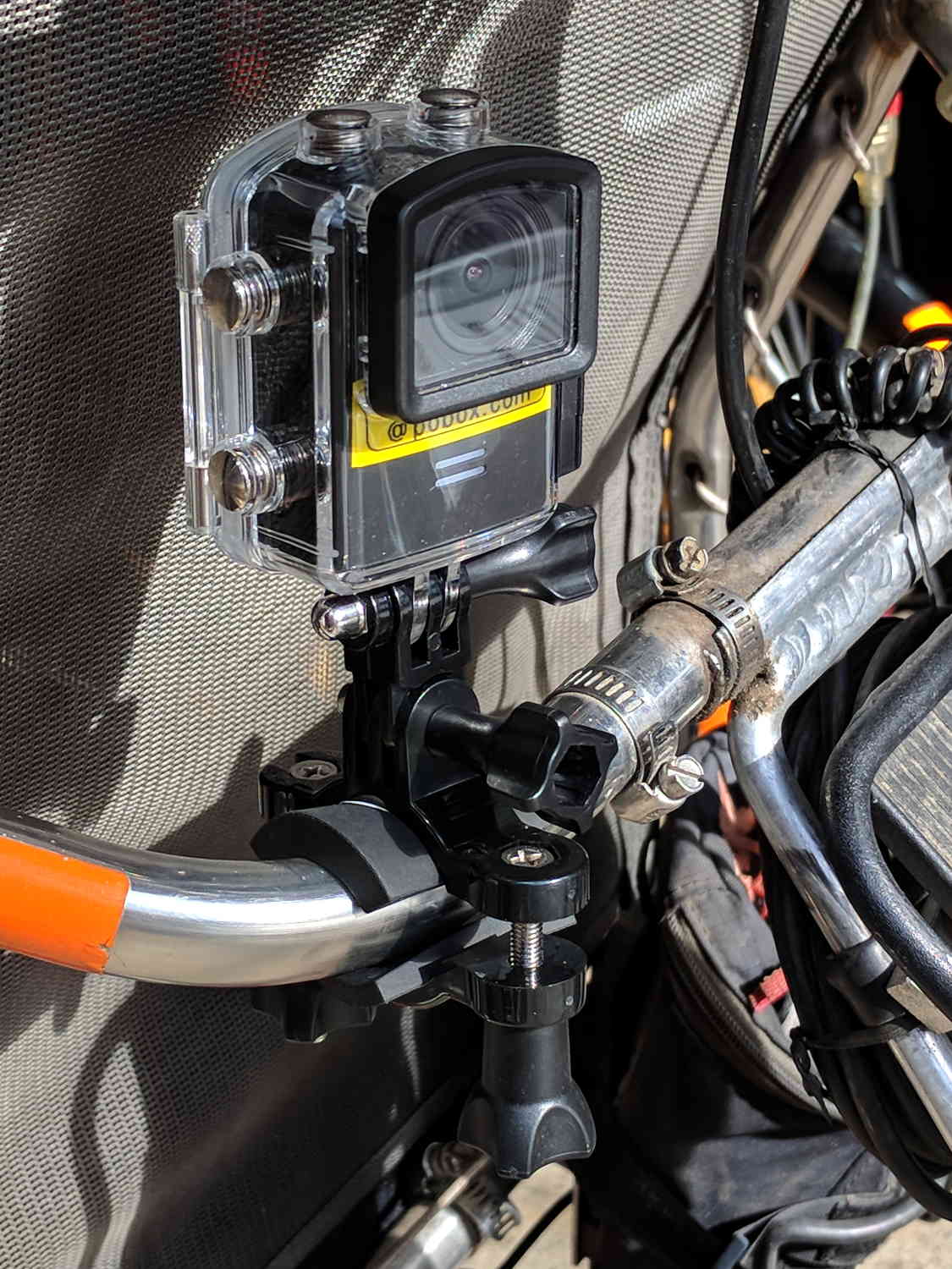
Including a waterproof case, some right-angle connectors, and a pipe clamp:
M20 in waterproof case – Tour Easy seat
The stack turns out to be about as flexy as one might imagine, definitely a Bad Thing for a bike-mounted camera, and a somewhat more rugged mount seems in order.
A diagram from the M20 manual shows the parts:
SJCAM M20 Overview – Manual pg 5
Some camera dimensions:
40.2 mm wide + 0.5 mm for the Up/Down buttons
21.8 mm thick + 1.0 mm cylindrical front curve + 1.0 mm rear screen
50.0 mm tall + 4.0 mm cylindrical top curve + buttons
21.7 mm OD × 6.0 mm long lens housing, 1.3 mm down from top center
All the edges have neat chamfers or radius rounding on the order of a few millimeters.
Applying the chord equation to the spans inside the rounding:
Front radius: 162.5 mm
Top radius: 42.5 mm
The new batteries survive for a bit over an hour, not quite enough for our usual rides. Rather than conjure a fake battery pack connected to an external 18650 cell with a wire chewed through the case, the least awful way to go may involve a relatively small battery pack (with internal 18650 cells, of course) plugged into the USB port with a right-angle cable and a rigid mount holding both the camera and the pack to the seat frame.
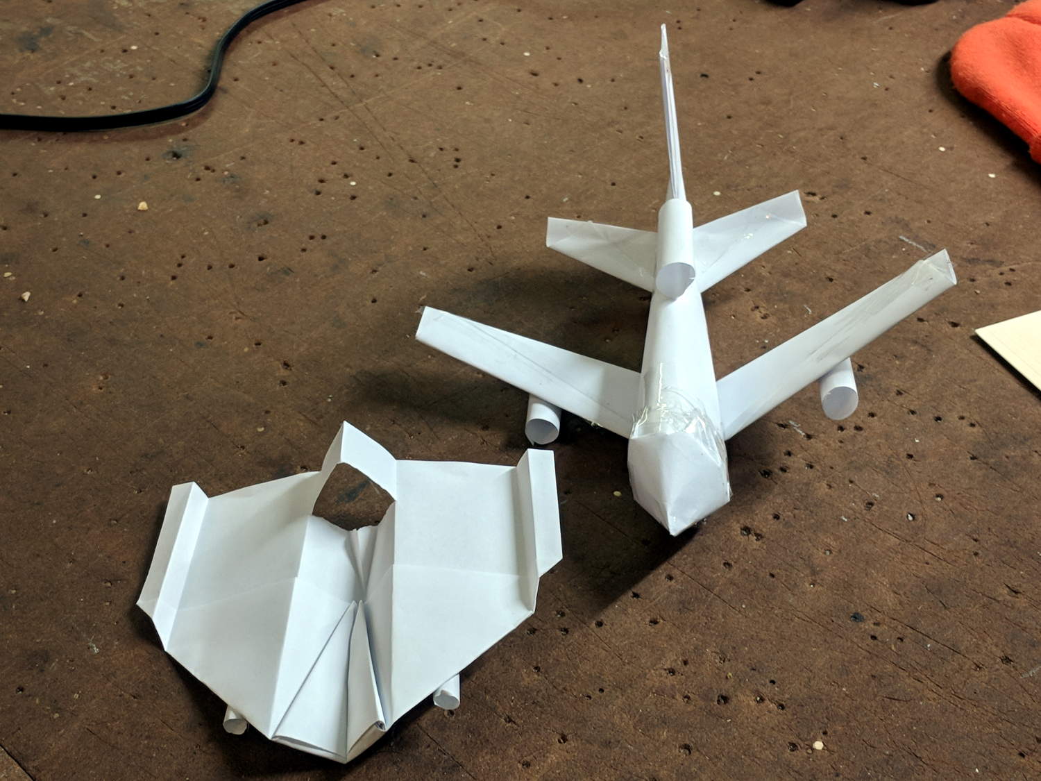
Milo showed how to construct his realistic-looking paper airplane design at Squidwrench, so I had to fold an airplane pattern I learned in fifth grade:
Paper Airplanes – front view
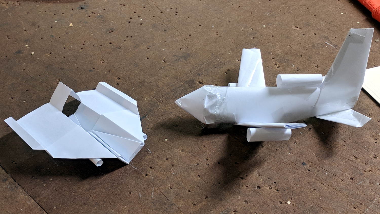
Side views:
Paper Airplanes – side view
Bottom views:
Paper Airplanes – bottom view
His plane flies fine, but “my” airplane has the virtue of simplicity. He had a snippet left over for a fourth engine, so I cut it in half and rolled a pair; the original pattern has none.
It flies best when made from a sheet of 8-½×11 inch (Letter) paper, but anything will suffice. Here’s how to fold one from a Geek Scratch Pad half-Letter sheet.
Start with two diagonal folds:
Best Paper Airplane Ever – 1
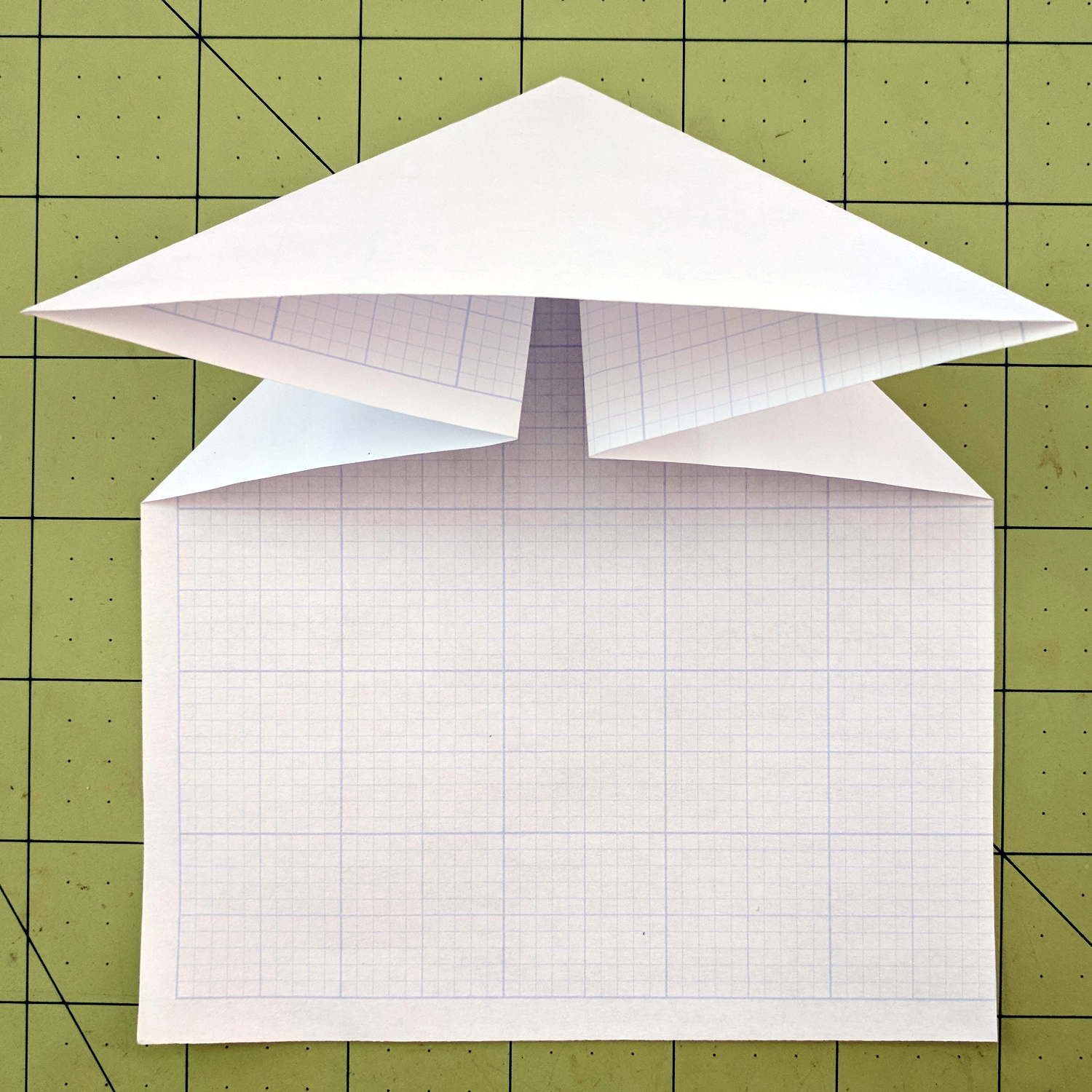
Push the sides in and flatten:
Best Paper Airplane Ever – 2
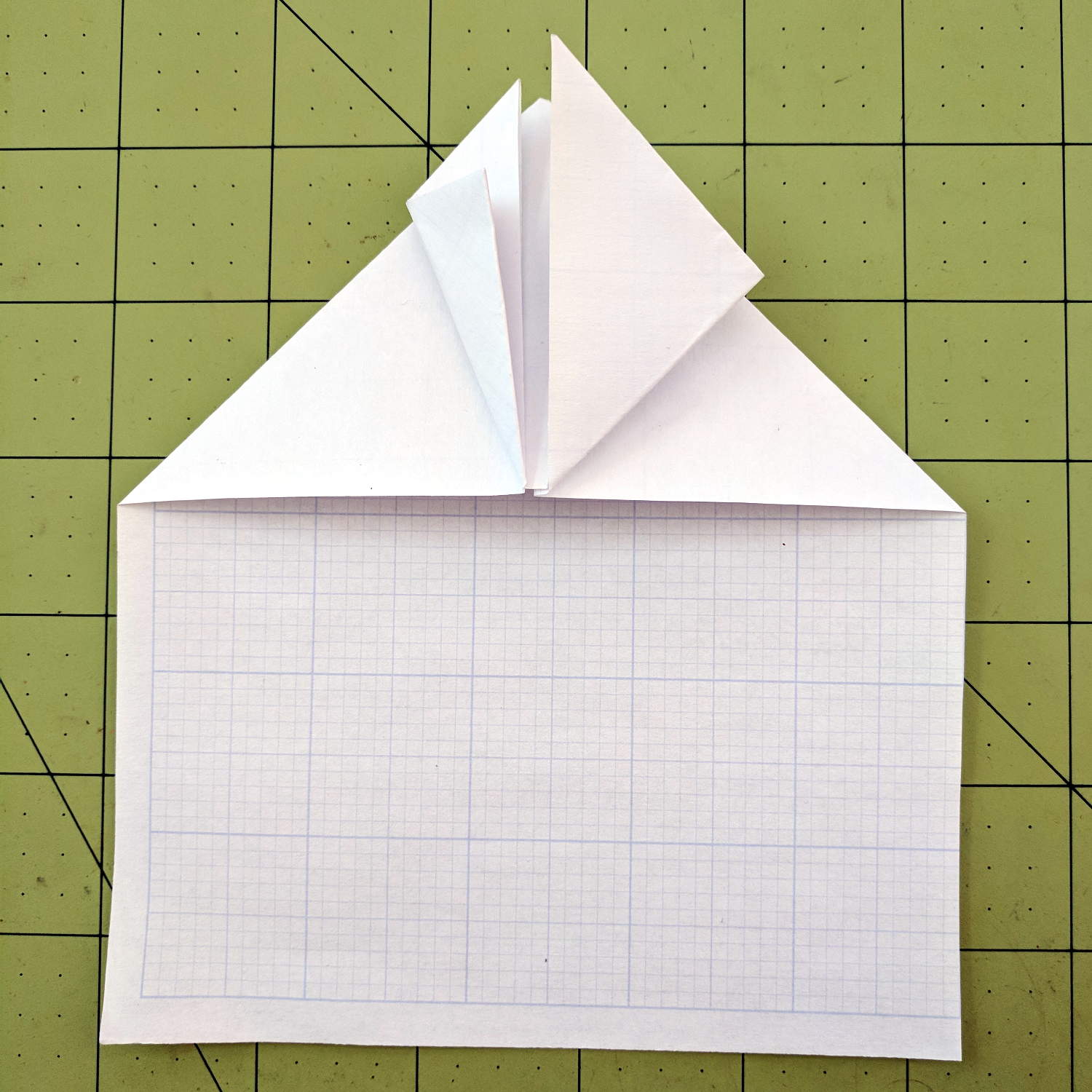
Fold the side tips forward, then again to form pockets:
Best Paper Airplane Ever – 3
I’ve always made those folds to leave a few millimeters of clearance along the centerline, but it probably doesn’t matter.
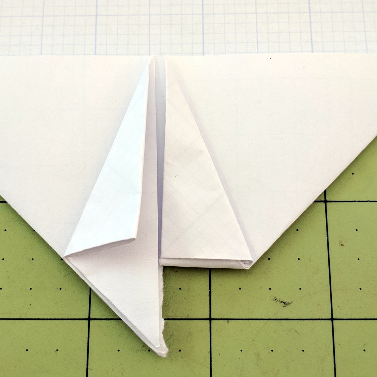
Tear the fuselage rearward from the nose, along the center line, back to the pockets:
Best Paper Airplane Ever – 4
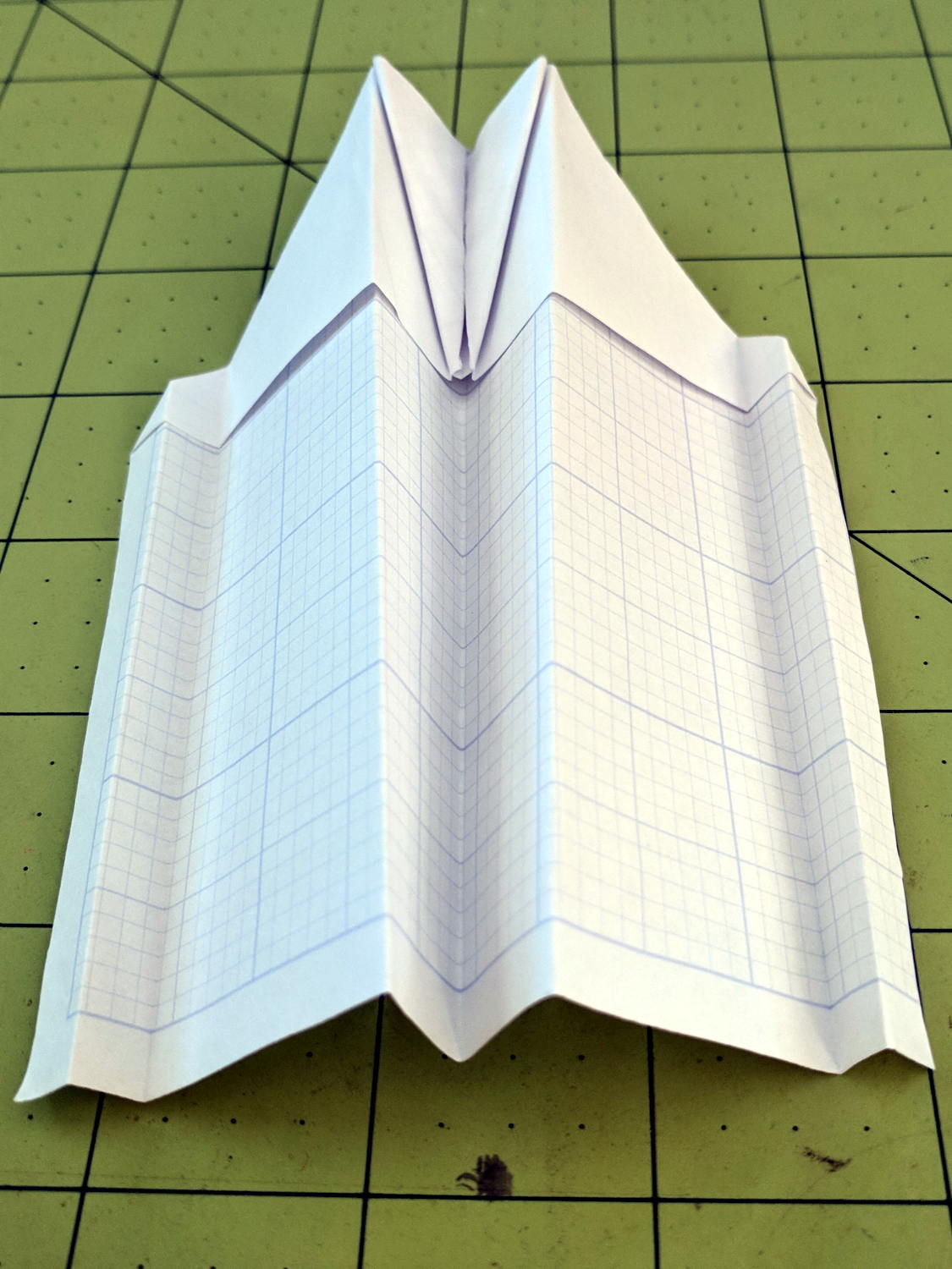
Tuck the nose pieces into the pockets, flatten firmly, then fold in half lengthwise:
Best Paper Airplane Ever – 5
Fold each wing downward from the pocket, upward to put the edge along the bottom of the fuselage, then fold downward to align the edge at the previous fold:
Best Paper Airplane Ever – 6
Which is harder to describe than to do. The end result should look like this:
Best Paper Airplane Ever – 7
Crisp the folds, tear a square-ish vertical-ish stabilizer, fold a triangle into the fuselage, then un-flatten the airplane into shape:
Best Paper Airplane Ever – 8
Grab just behind the pockets, toss gently upward, and it’ll fly fine the first time. Slightly bend the rear edges of the wing and stabilizer to trim the flight path until it sails gently across the room.
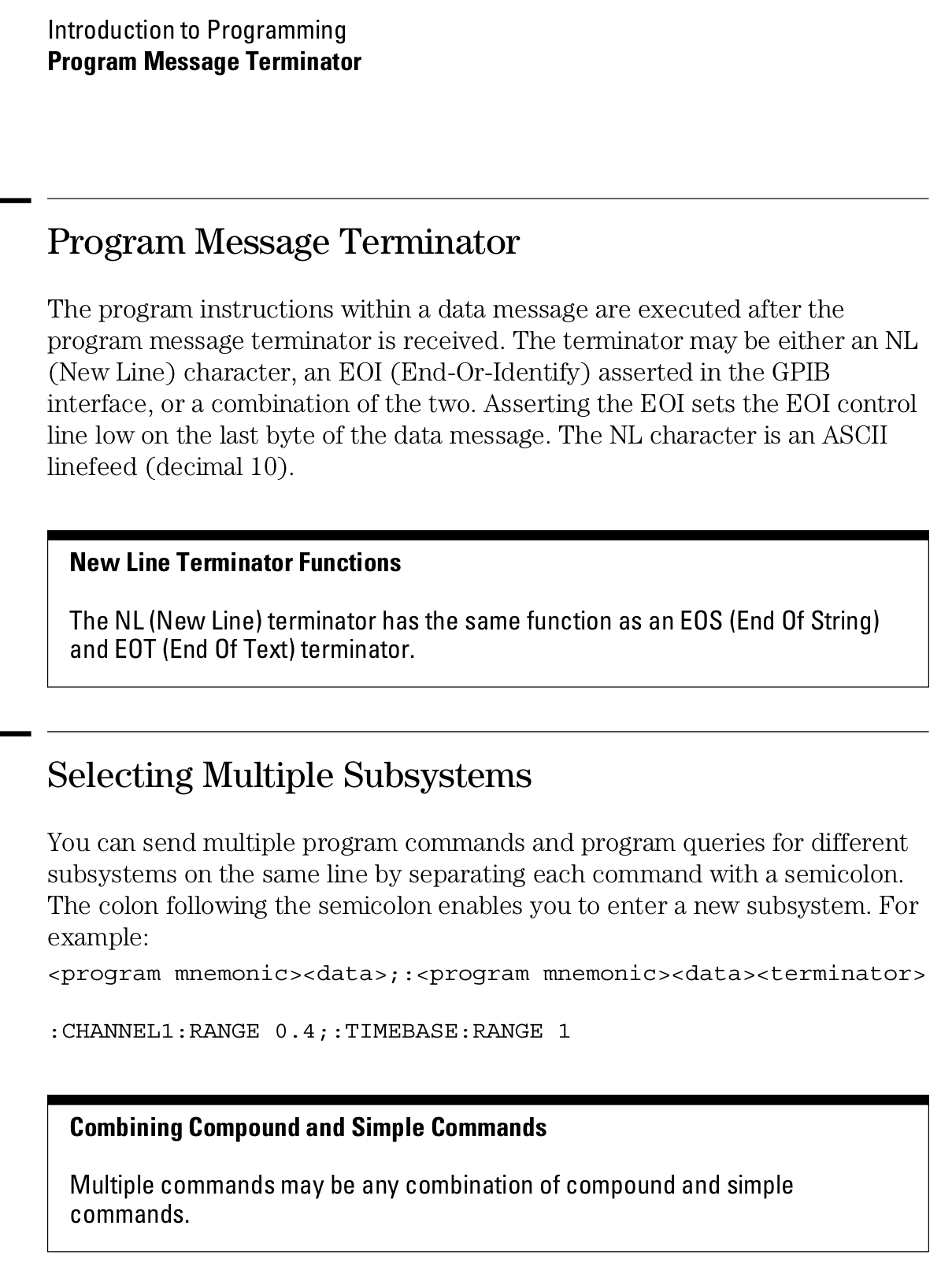
Gastón sent me a note describing how he got serial communications working with an old-school HP 54600-series oscilloscopes. After swapping some hints and tests, it’s worth recording so I (and, perhaps, you!) can make use of it the next time around:
I recently bought a 54616B for which I also bought the 54659 Measurements/Storage module. It comes with an RS232 9-pin port and that, besides the possibility to have the full plethora of additional measurements including FFT, made me buy it.
I saw I had the same problem you had by that time (the oscilloscope printed alright through the serial port but utterly ignored all of the commands I sent to it) so, as I found a solution, I thought it would be nice to share it with you as you share all of your doings with many people on the web.
I discovered that the real problem was not in the interface but in the documentation (go figure, huh!). The terminator character must be, instead of a NL, a semicolon. The NL terminator is probably still valid for the GP-IB interface.
I have tested this setup at 19200 baud, “DTR” flow control on the scope side and a generic USB-Serial converter (Cypress semiconductor) plus a null modem cable and it worked just fine. The software on my PC is Windows 7, but I am running an Xubuntu Xenial under Virtualbox and did the tests using minicom.
Sending NLs did not seem to affect the communication at all but be aware that the error handling routines on the scope side are not the best, meaning that most probably after some errors or just one (which you will see emerge on the scope screen) you will need to reboot the scope to be able to communicate again. No big deal but it could be annoying.
This is a sample of a command sequence to measure the frequency of the calibrator connected to the Channel 1 input:
Let me know if it works for you, or if I can be of any help.
Which knocked me out of my chair!
Wow!
That’s the first time the scope’s serial output pin produced a different voltage in the last, uh, three decades! [grin]
You’re absolutely right about the command parser: it falls off the rails at the slightest provocation and leaves no suicide notes behind.
Gingerly following your technique, I found the scope’s serial interface must be in its “connected to computer” mode; the printer & plotter modes (not surprisingly) don’t respond to commands.
Even with that, I’m unable to get a consistent response to (what seem to be) correctly formatted commands. If I send some *RST; commands, eventually it’ll reset, but I sometimes can’t get anything back from status inquires like *SRE?; and so forth.
Sometimes, a linefeed (Ctrl-J) works as a terminator, sometimes it doesn’t. Even with a semicolon at the end of the command, it sometimes responds only after a Ctrl-J. Recovering from errors seems to require a random number of successive ; and linefeed characters.
What definitely doesn’t work: a normal carriage return + linefeed combination! I think that explains my complete lack of success many years ago, as I probably used a terminal program that automatically sent CR+LF at the end of each line.
However, it’s now doing something in response to serial commands, which it never did before.
The only way to use the interface will be with a (tediously debugged) program sending a preset command sequence and receiving a known series of responses. Hand-carving a series of commands just won’t work.
Gastón did a bit more poking around:
It seems that the implementation for the different oscilloscopes of the same family was different. This was to be expectable but I didn’t think it would be *so* different.
In my case, as said, linefeed does nothing at all. This weekend I will try (just for grins of course) to use linefeeds interspersed with the letters of a single command to see to what extent they are ignored.
In my opinion, the inconsistent response you get could have to do with the implementation of the interface on the computer side, or even marginal baud rate or jitter. I had to resort to the Xubuntu-within-Virtualbox-within-Windows7 just because I couldn’t get a consistent communication from Windows 7 alone from my “usual” laptop. I tried another laptop with Xubuntu as OS and the serial port worked only up to 9600 baud, and with some errors from time to time, shown as “Override error” and “RS232 Protocol Error” on the scope screen. From this ones, the oscilloscope did recover without problems. Parser ones in my case are fatal every time. They show as “Unknown Header” and that’s a death signal. The oscilloscope functionality, though, is not affected in any way.
Just as an aside, my HP 54659A interface uses a Philips SCN2661AC1A28 as UART.
I agree with you regarding to the way to use it is with a program that only sends the right sequence of commands and receives in turn a known series of responses. Back in the ’90s I worked with a functional level board tester which used several HPIB-managed instruments (HP3314 arbitrary waveform generator, two programmable power supplies), a couple others with VXI bus, among which there was a display-less version of an HP545xx oscilloscope. That beast was managed from an IBM PS/2 model 70 (a 486 based one) with National Instruments interface boards. Not a hobby setup in any way. Every single time I managed to send the wrong command to the oscilloscope, I had to reboot both the board tester rack and the PC… so the parser’s lack of humor is not exclusive of the 546xx series :).
Even with a fully debugged command sequence, sometimes the oscilloscope decided to act up… this last didn’t happen very often but when it did, it was extremely annoying for the tester operator as the sequence was a lengthy one (about 10 minutes per board) and when it failed, it meant sometimes half an hour of time lost, between recognition of a tester failure (and not simply a board that required multiple test retries and thus took longer than usual), reboot of both instruments rack and computer, and rerun.
And a followup which may discourage all but the stout of heart:
To add to the general confusion, I tried with Ctrl-J instead of a semicolon, and the commands are accepted too. It seems that my tty terminal setup is not as good as I thought it was.
The semicolon, from what I have been reading, is a command separator within a line and perhaps that is why it is accepted as readily as the linefeed. I did test sending newlines between the characters and I got a “Syntax Error” in the scope screen from which the only way to recover was an oscilloscope reboot.
Page 1-12 from the Programmer’s Guide (54600-97032) may be of interest (clicky for more dots):
The hole fits a 25 mm fan, but the thing runs cool enough it should survive without forced air; think of it as a contingency. Mounting the case on standoffs seems like a Good Idea, however, as the bottom plate includes many vent slots for Good Circulation.
The top plate builds upside-down, so I had Slic3r add teeny support plugs inside the recessed screw holes. I think button-head screws would fit neatly in the recesses, but we’re obviously not in this for the looks.
The tiny white stud is a Reset switch hot-melt glued into the slot. I plan to just turn off the AC power after shutting the RPi down, so a power-on will suffice as a reset.
The Fly6 records 1280×720 @ 30 fps, with somewhat high contrast and weird color balance:
Fly6 – Backlit license
It works better with a stationary target in good light:
Fly6 – Stationary license
The M20 records 1920×1080 @60 fps (among many other choices), with reasonable contrast and coloring:
M20 – backlit license
Good lighting and no motion helps it along, too:
M20 – Stationary license
The original frames-grabbed-from-the-video aren’t visibly different from the JPGs you see here.
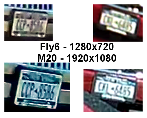
Collecting all the plates in one montage:
Fly6 vs M20 – License Plates
I enlarged the left pair by 200% and the right pair by 300%, using GIMP’s cubic interpolation, to make them large enough to see with the naked eye. The interpolation algorithm slightly smooths the edges, but the cameras put those weird compression artifacts / blobs in the original images.
The left pair also got auto-brightness adjustments to drag ’em out of the murk.
I saved the montage as a PNG, rather than a JPG, although JPG image compression made no difference.
All in all, the M20 has better image quality than the Fly6, but its 1.5× higher resolution isn’t a slam-dunk win and, IMO, video compression has more effect than image resolution. The Fly6 has no compression controls and I’ve set all the M20 controls to as good as they can be.
Both those license plates sport NYS’s now-obsolete high-contrast blue-on-white color scheme: the current blue-on-gold NYS plates have much lower contrast. In this age of ubiquitous license plate reading and storing, I cannot explain why this was allowed to happen.
The Fly6, now equipped with a high-quality 18650 lithium cell, should have more hours of run time than I can measure this early in the season. Perhaps six hours, with its red blinky LED at full throttle, according to the doc.
The M20 lasted 72 minutes with a freshly charged battery, which means it didn’t quite survive the trip. Performing battery maintenance in the middle of a ride for groceries isn’t appealing; I should conjure an external 18650 battery pack for the thing.