Ed Nisley's Blog: Shop notes, electronics, firmware, machinery, 3D printing, laser cuttery, and curiosities. Contents: 100% human thinking, 0% AI slop.
Tag: Improvements
Making the world a better place, one piece at a time
My venerable amateur radio HT APRS-voice interfaces have recently begun failing and, given poor APRS coverage in Poughkeepsie due to having two iGates shut down (due to the aging radio geek population), I decided it’s time to simplify the radio interface. Given that HTs are designed to run with an external electret mic and earbud, the “interface” becomes basically some wires between the radio’s jacks, a repurposed USB plug on the bike helmet, and the PTT switch on the handlebar.
I expected to add a resistive attenuator to the earbud, but it wasn’t clear whether the mic would need an amplifier similar to the one in the APRS interface, so I decided to start as simply as possible.
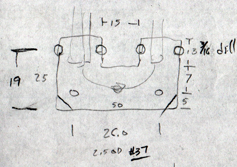
The general idea is to anchor all the cables to a plate on the back of the radio, interconnect as needed, then “protect” everything with tape. The pocket clip has M2.5 screws on 26 mm (not 25.4, honest) centers, so that’s how it started:
Baofeng headset wire plate – dimensions
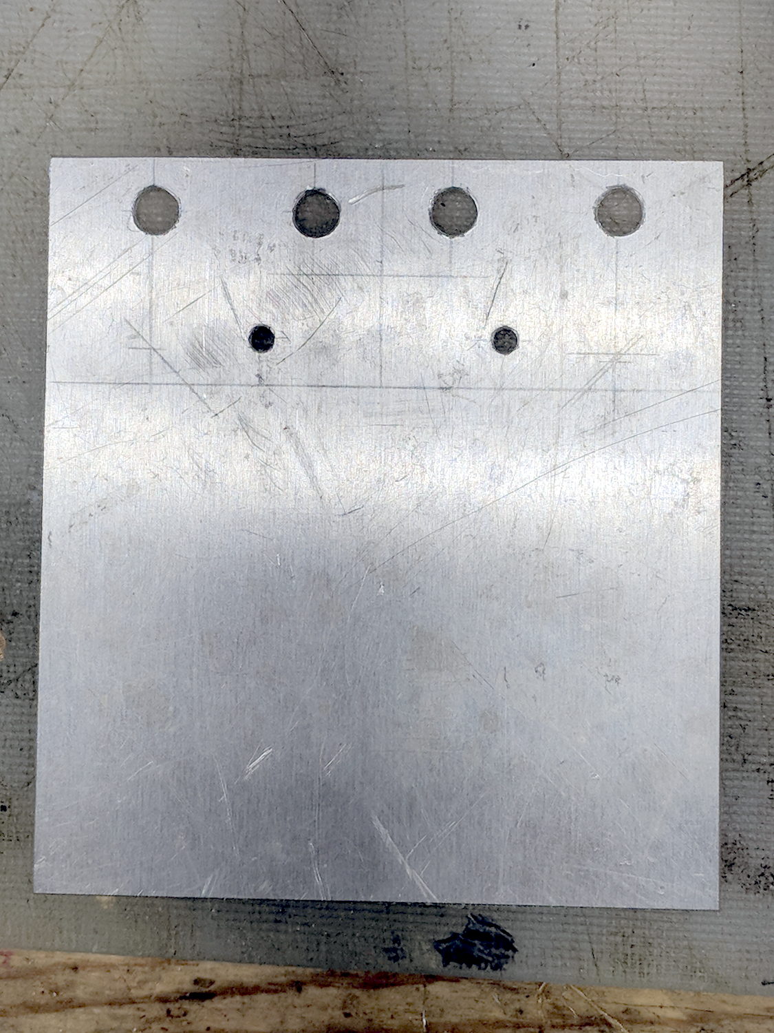
The four holes beside the tabs will serve as starting points for rectangular notches holding cable ties lashing the wires to the plate:
Baofeng headset wire plate – drilled
Like this:
Baofeng headset wire plate – sawed
That’s hot and nasty, straight from the bandsaw.
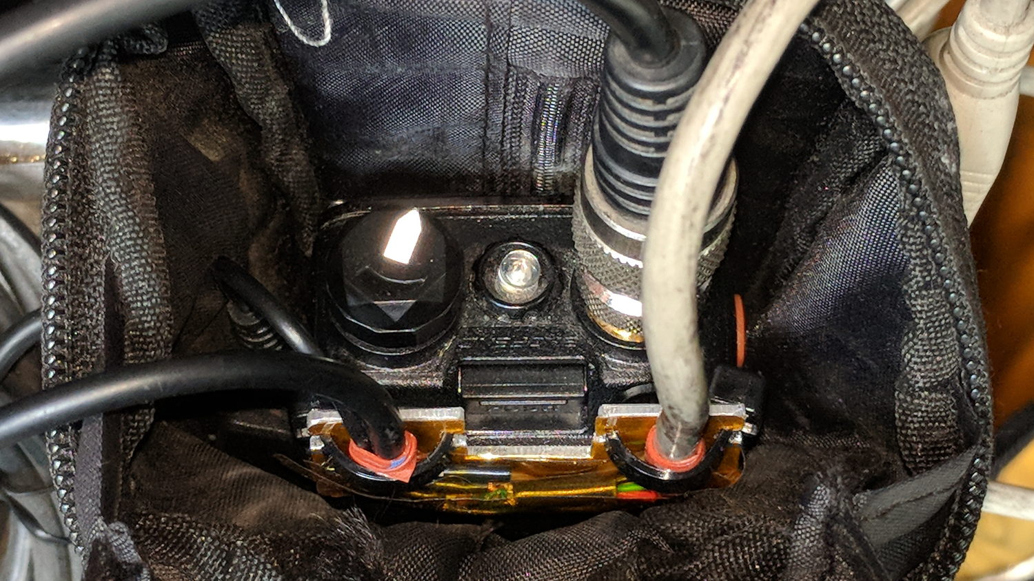
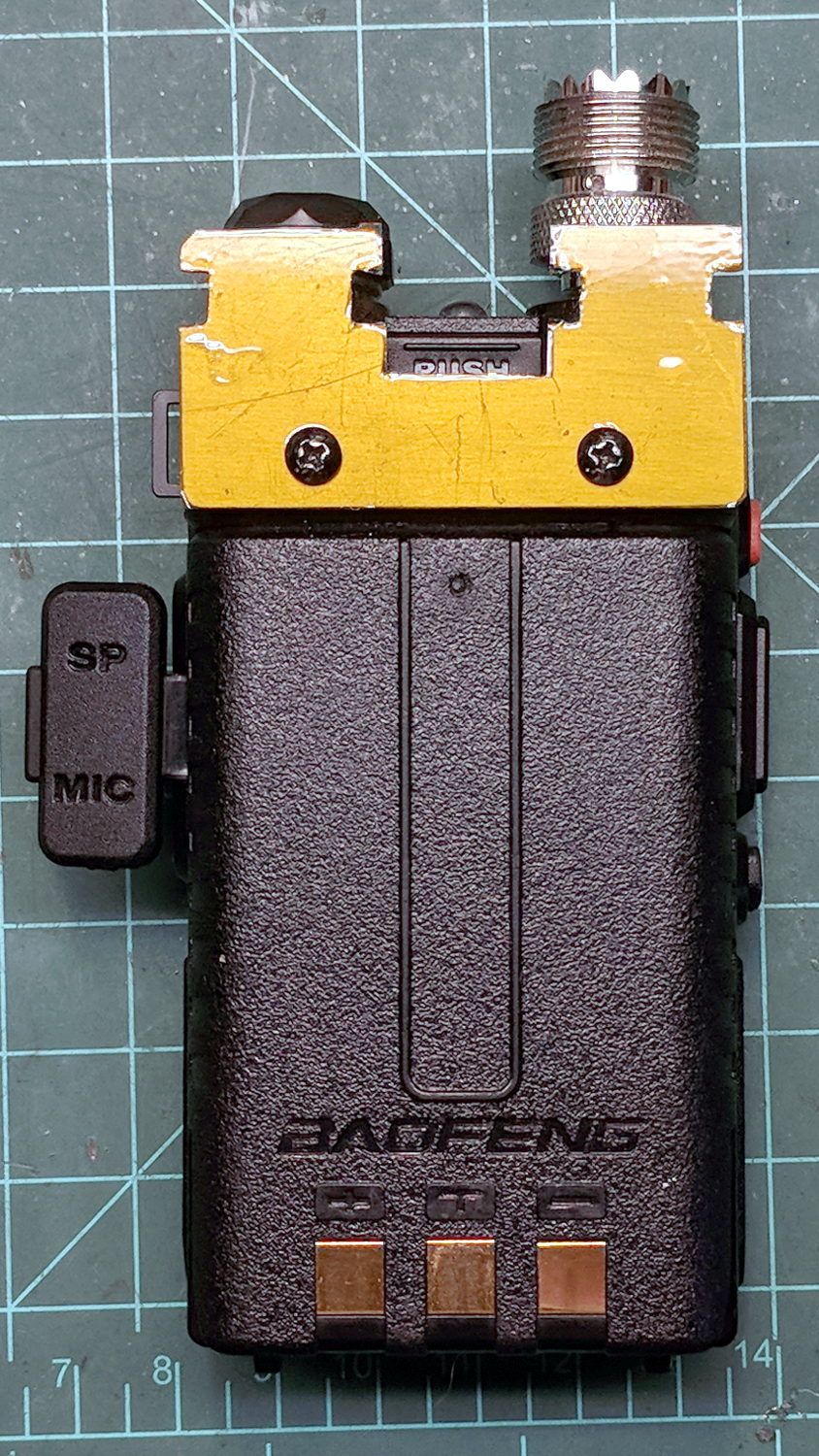
After some edge cleanup, add obligatory Kapton tape to insulate stray wires from the aluminum:
Baofeng headset wire plate – installed
The alert reader will note beveled corners on one plate and square corners on the other; think “continuous product improvement”.
The big rectangular gap in the middle of the plate provides (barely enough) finger clearance to push the battery release latch.
Now, to wire it up …
The dimensions of the recess surrounding the jacks on the Baofeng UV-5, just to have them around:
Baofeng headset jack socket – dimension doodle
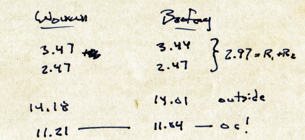
Which came from measurements of both the Wouxun and Baofeng radios:
Baofeng Wouxun headset jack sockets – measurements
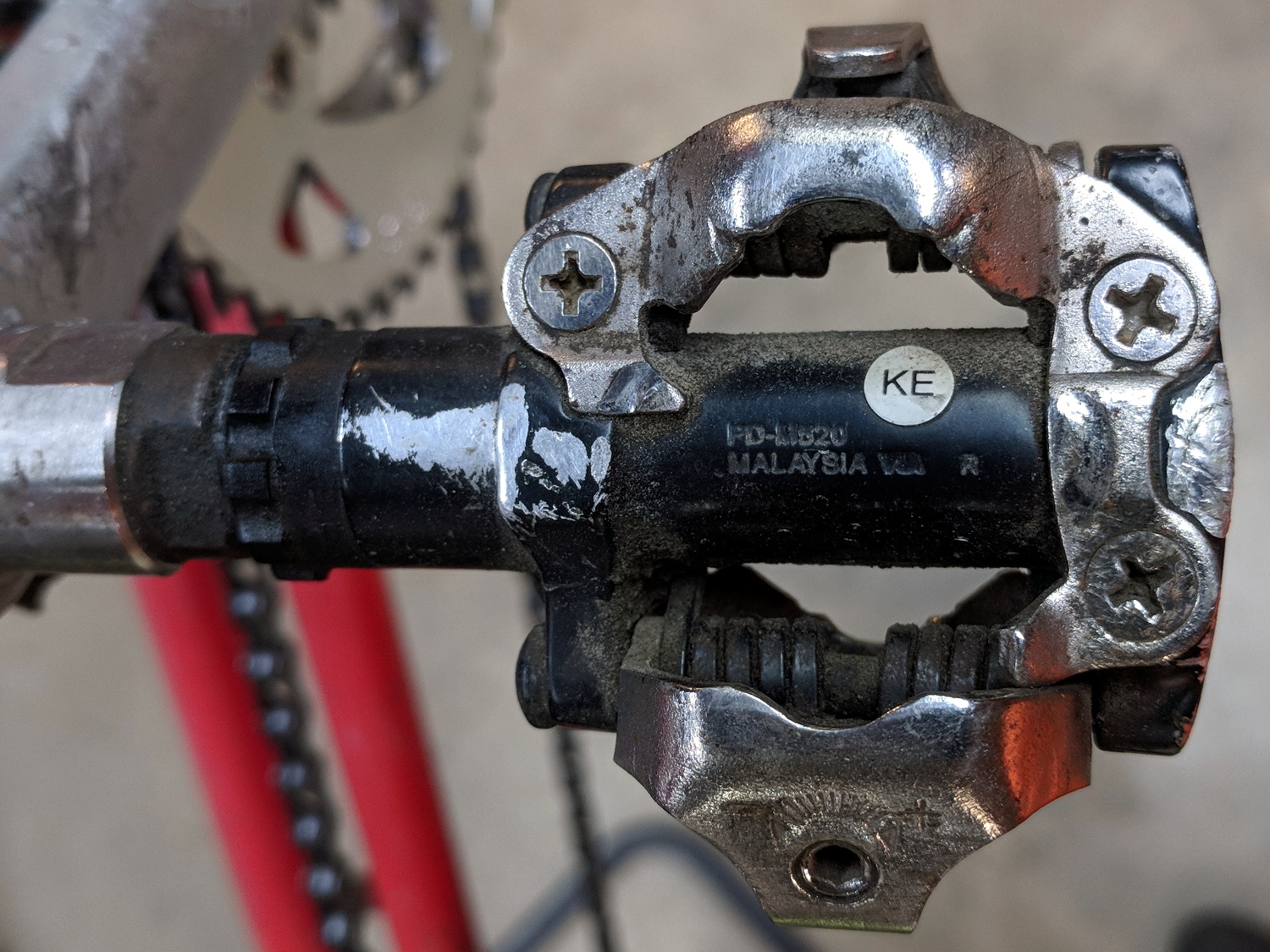
But the soles jammed against the frame on the PD-M324 pedals.
So I carved away enough rubber around the cleat sockets for clearance to float properly with the cleats latched. A bit of trial-and-error, probably with a bit more to come after on-the-road experience, but definitely a step in the right direction.
Protip: always always always arrange the workpiece so the blade trajectory cannot intersect any part of your body, no matter what slips occur.
The front rim on my Tour Easy developed a distinct bulge, of the sort usually caused by ramming something, but I’m not Danny McAskell and the bulge got worse over the course of a few weeks, suggesting the rim was deforming under tire pressure. Having ridden it upwards of 35 k miles with plenty of trailer towing and too much crushed-stone trail riding, the brake tracks were badly worn and it’s time for a new rim.
An Amazon seller had an identical (!) rim, except for the minor difference of having a hole sized for a Schraeder valve stem, rather than the Presta valves on the original rims. One can buy adapters / grommets, but what’s the fun in that?
The brake track walls are 1.5 mm thick on the new rim and a scant 1.0 mm on the old rim, so, yeah, it’s worn.
A few measurements to get started (and for future reference):
Presta to Schraeder Adapter – dimension doodle
If you don’t have an A drill, a 15/64 inch drill is only half a mil larger and, sheesh, anything close will be fine.
Introduce a suitable brass rod to Mr Lathe:
Presta-Schraeder Adapter – parting off
Break all the edges and drop it in place:
Presta-Schraeder Adapter – installed
One could argue for swaging the adapter to fit flush against the curved rim, but commercial adapters don’t bother with such refinements and neither shall I.
The 7.0 mm length got shortened to fit flush with the center of the rim:
Presta-Schraeder Adapter – valve stem installed
It’s brass, because the rim is heaviest on the far side where the steel pins splicing the ends live, and, with the tube & tire installed, the rim came out almost perfectly balanced. Which makes essentially no difference whatsoever, of course.
The shiny new rim sports shiny new reflector tape (from the same stockpile, of course).
A long time ago, a pair of white LED + red laser flashlights powered by an AA cell diverged: one flashlight worked fine, the other always had a dead battery. The latter ended up on my “one of these days” pile, from which it recently emerged and accompanied me to a Squidwrench Tuesday session:
Small Sun flashlight – original wiring
The black wire trailing from the innards goes to the battery negative terminal, with the aluminum body providing the positive terminal connection to the wavy-washer spring contact visible atop the rear PCB inside the front shell.
The switch connects each red wire to the battery negative terminal, so there’s a color code issue in full effect. The two red wires burrow through holes in the rear PCB (shown above) and connect to the negative terminal of the laser module (the brass cylinder near the top) and the negative terminal ring on the front PCB holding the seven white LEDs:
Small Sun flashlight – original wiring – LED laser board
Continuing the color code issue, the black wire from the laser is its positive terminal. The out-of-focus wire (an LED pin) sticking up near the top of the picture carries the positive connection to the LED ring. The red wires from the switch are the negative connections for the LEDs and laser.
Voltages applied to the LED ring and the currents flowing therein:
Small Sun flashlight – 7x white LED current vs voltage
Seven LEDs at 20 mA each = 140 mA, so the voltage booster must crank out slightly more than 3.2 V. They’re not the brightest white LEDs I’ve ever seen, but suffice for a small flashlight.
A crude sketch of the PCB layout, with a completely incorrect schematic based on the mistaken assumption the SOT23-3 package was an NPN transistor:
Small Sun flashlight – schematic doodle
Obviously, that’s just not ever going to oscillate, even if the 2603 topmark meant a 2SC2603 transistor, which it doesn’t.
A bit more searching suggests it’s a stripped-down Semtech SC2603A boost converter, normally presented in a SOT23-6 package. If you order a few million of ’em, you can strip off three unused pins, do some internal rebonding, and (presumably) come out with an SOT23-3:
Small Sun flashlight – correct schematic doodle
That topology makes more sense!
Before going further, I had to rationalize the colors:
Small Sun flashlight – rewired LED laser board
Soldering longer leads to the PCB allows current & voltage measurements:
Small Sun flashlight – LED current test
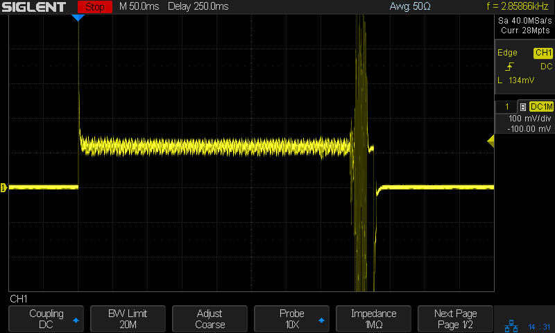
With the LEDs and laser disconnected, the converter seems to be struggling to keep the capacitor charged:
Small Sun flashlight – V boost I 200mA-div – idle
Those purple spikes come from the current probe at 200 mA/div: maybe half an amp in 5 μs pulses at 6 kHz works out to a 15 mA average current, which is pretty close to the 11 mA I measured; it’s not obvious the Siglent SDM3045 meter was intended to handle such a tiny duty cycle.
Obviously, the output capacitor is junk and, after removing it, the AADE L/C meter says NOT A CAPACITOR. Perhaps it never was one?
Measuring the cap in the good (well, the other flashlight) suggests something around 100 nF, so I installed a random 110 nF cap from the stash. The current peaks are about the same size:
Small Sun flashlight – I 200mA-div – 110nF cap
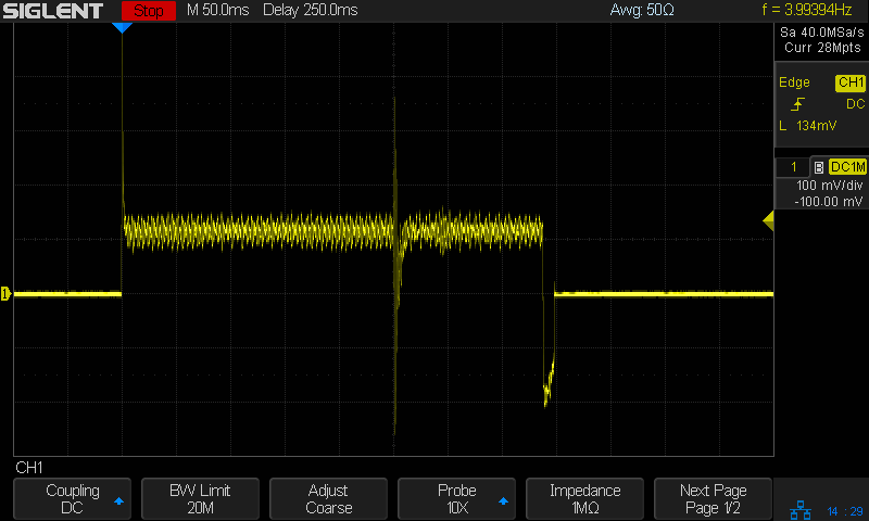
The cap voltage (not shown) is now nearly constant and the 50 Hz PWM rate reduces the average battery current to 100-ish μA:
Small Sun flashlight – I 200mA-div – color-grade – 110nF cap
Not great, but tolerable; a 1000 mA·h battery will go flat in a few months.
The LED current runs a bit hotter than I expected:
Small Sun flashlight – I 200mA-div – LED current – 110nF cap
The bottom is about 200 mA and the average might be 350 to 400 mA.
Compared with the other flashlight:
Small Sun flashlight other – I 200mA-div – LED current
So the cap is maybe a bit too small, but it likely doesn’t matter.
And, because they’re firmly attached to the fairing mount, there’s no way to tilt them to extract the 18650 cell.
This took entirely too long to figure out:
Lithium 18650 Cell Extractor Tab
The LC40 end caps have a recess exactly where it’ll do the most good: capturing the tab inside the cap means it can’t interfere with the rear contact spring:
Being that sort of bear, I (sometimes) note the date on cells when I change them, as with this notation on the AA alkaline cells in the Logitech trackball:
Amazon Basics AA cell – mouse runtime
These Amazon Basics AA cells lasted almost exactly two years, compared with 15 and 20 months from the previous two pairs of Duracell AAs. A few months one way or the other probably don’t mean much, but the Amazon cells aren’t complete duds.
The new Amazon Basics cells have a gray paint job, so they’ve either changed suppliers or branding.