Ed Nisley's Blog: Shop notes, electronics, firmware, machinery, 3D printing, laser cuttery, and curiosities. Contents: 100% human thinking, 0% AI slop.
Tag: Improvements
Making the world a better place, one piece at a time
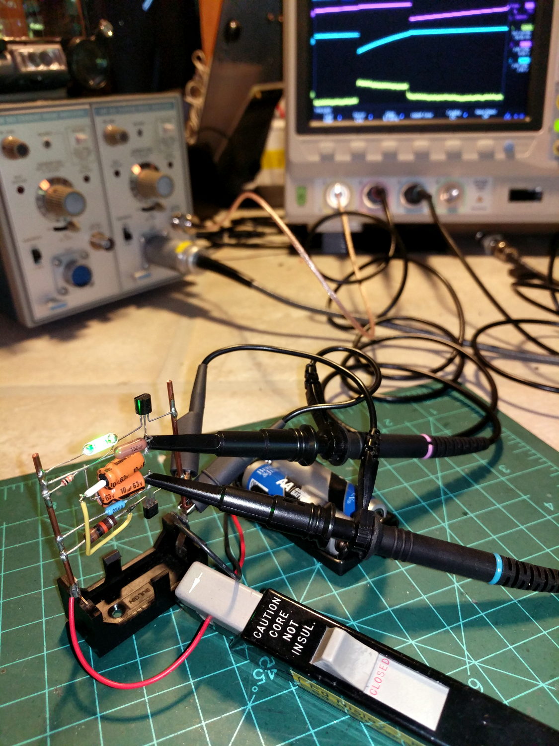
The question occasionally comes up as to why one would want a Tektronix A6302 Hall effect current probe and AM503 amplifier. The answer is simple: non-contact, essentially non-invasive current monitoring.
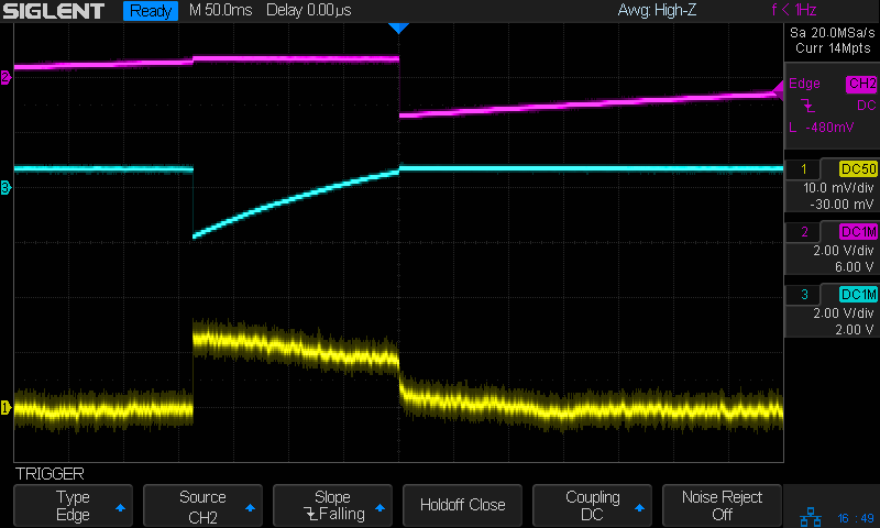
The scope screen in the background shows the two base voltages at the top, plus the overall battery current along the bottom:
Tek A6302 – Astable multivibrator – LED current 1 mA-div
The current at 1 mA/div shows plenty of noise, but the 200 ms LED pulse is barely 1 mA tall. The two AA alkaline cells have faded to 2.5 V, so the “wearable” white-LED-with-dyed-overcoat runs far under its nominal 3.6-ish V spec.
There’s basically no other way to get that result, because inserting a current-sense resistor into the circuit will alter the results, plus be intractably difficult to measure, particularly if you need the current in a non-ground-referenced branch of the circuit.
The AM503 has terrible thermal drift, by contemporary standards, but after the first half-hour or so it’s manageable for short durations. I’m thinking of epoxying a small knob to the screwdriver-adjustable twiddlepot to simplify the baseline adjustment.
Alas, even non-working probes and amps have become eBay collectables. You could, of course, buy new.
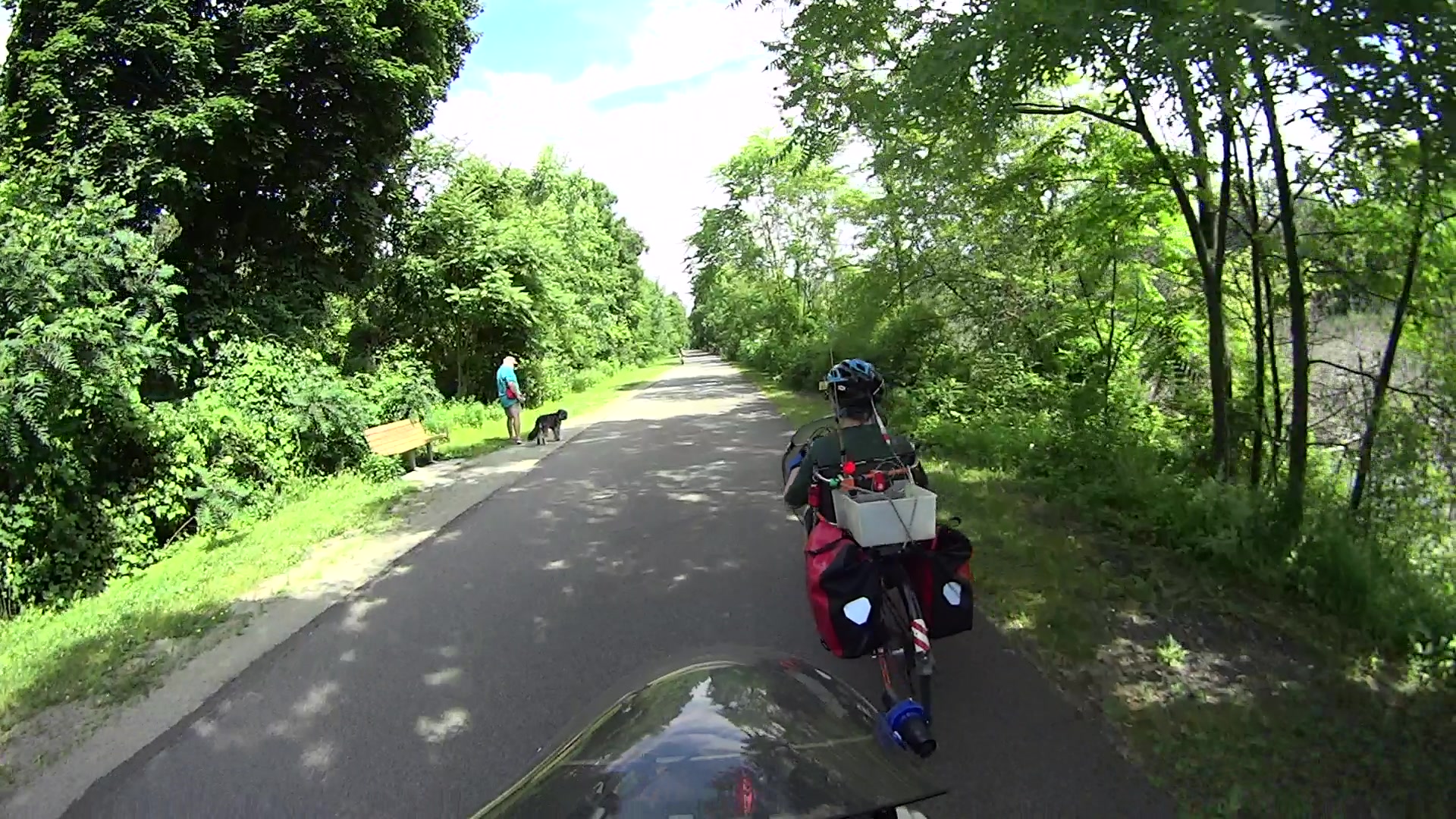
Although the pair of Ortlieb Back-Roller packs on Mary’s bike make her look like a long-distance tourist, we’re actually on our way to her garden plot:
AS30V-0285
The left-side pack suddenly seemed unusually floppy:
AS30V-0300
One second later:
AS30V-0360
Another second and it’s visible under my right hand:
AS30V-0420
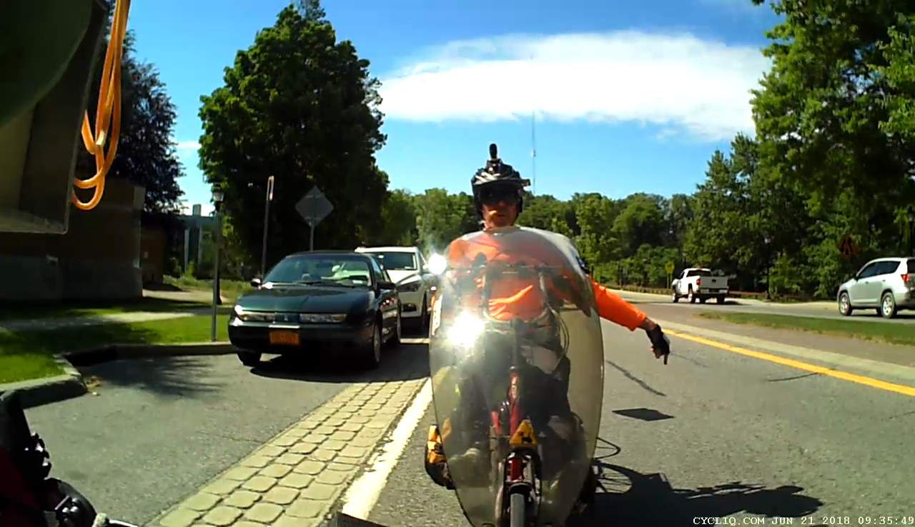
The view from her bike at about the same time:
Ortlieb-0158
I’m expecting to fall to my right, but it’d have been better if I hadn’t kicked the bag:
Ortlieb-0169
The pack went under the rear wheel and out the far side:
Ortlieb-0185
Where it came to rest in the middle of the trail:
Ortlib pack drop – aftermath
Elapsed time from the first picture: just under 5 s.
Did you notice the other cyclist in the other pictures? She’s why I veered so hard to my right!
A pair of these latches hold the pack onto the rear rack:
Ortlieb pack drop – QL latch detail
When they’re properly engaged, they look like this:
Ortlieb pack drop – QL latch – secure
When they’re not, they look like this:
Ortlieb pack drop – QL latch – whoopsie
Which is obvious in the picture and inconspicuous in real life.
The strap emerging from the top of the latch serves as both a carrying handle and latch release: pull upward to open the latches and release them from the bar, lift to remove the pack, and carry it away as you go. Installing the pack proceeds in reverse: lower the pack onto the rack bar, release the handle, and the latches engage.
Unless the pack is empty enough to not quite fully open the latches as you carry it, in which case the closed latches simply rest on the bar. We’ve both made that mistake and I generally give her packs a quick glance to ensure sure they’re latched. In this case, the plastic drawer atop the racks (carrying seedling pots on their way to the garden) completely concealed the pack latches.
Tree roots have been creasing the asphalt along that section of the rail trail: the bike finally bounced hard enough to lift the drawer and fall off the rack rod.
Memo to Self: In addition to the visual check, lift the packs using the strap across the middle holding the rolled-down top in place. Remember, don’t check by lifting the carrying handle, because it just releases the latches; another easy mistake to make.
You get those by plugging everything in, running blkid, and sorting out the results.
The 64 GB MicroSD card from the Sony AS30V camera uses Microsoft’s proprietary exfat file system, which apparently doesn’t associate a UUID/GUID with the entire device, so you must use a partition label. The Official SD Card Formatter doesn’t (let you) set one, so:
exfatlabel /dev/sdd1 AS30V
It turns out you can include spaces in the partition label, but there’s no way to escape them (that I know of) in /etc/fstab, so being succinct counts for more than being explanatory.
One could name the partition in the Windows device properties pane, which would make sense if one knew it was necessary while the Token Windows Laptop was booted with the card in place.
I think this is easier then trying to persuade UDEV to create known device names based on the USB hardware characteristics, because those will depend on which USB card / device / reader I use. I can force the UUIDs to be whatever I want, because they’re just bits in the disk image.
With all that in place, you plug in All. The. Gadgets. and run the script (as seen below). The general idea is to verify the bulk video drive mounted OK, attempt to mount each memory card and fire off a corresponding rsync copy, wait until they’re all done, tidy the target filenames, then delete all the source files to get ready for the next ride.
Funneling all three copies to a single USB hard drive probably isn’t the smartest thing, but the overall write ticks along at 18 MB/s, which is Good Enough for my simple needs. If the drive thrashes itself to death, I won’t do it again; I expect it won’t fail until well outside the 1 year limited warranty.
If any of the rsync copies fail, then nothing gets deleted. I’m a little queasy about automagically deleting files, but it’s really just video with very little value. Should somethinghorriblehappen, I’d do the copies by hand, taking great care to not screw up.
After all, how many pictures like this do we need?
This file contains hidden or bidirectional Unicode text that may be interpreted or compiled differently than what appears below. To review, open the file in an editor that reveals hidden Unicode characters.
Learn more about bidirectional Unicode characters
This file contains hidden or bidirectional Unicode text that may be interpreted or compiled differently than what appears below. To review, open the file in an editor that reveals hidden Unicode characters.
Learn more about bidirectional Unicode characters
Both my Tek 2215A and HP 54602 oscilloscopes came with snap-on front covers to protect all those delicate knobs and connectors. Not so the Siglent SDS2304X, which is basically a flat shoebox with a handle: the case has no features for a cover to snap onto, Siglent doesn’t offer a padded carrying case, and it’s too thick big for any of the laptop bags around here.
I’ve been lugging it to Squidwrench meetings and can easily visualize a gash across the LCD panel or a knob rammed against a door frame.
So I trimmed a pair of foam angles, punched holes to fit around the knobs along the right edge, cut up a cardboard tray from the heap, and duct-taped the whole mess together:
Siglent SDS2304X Oscilloscope – crude front cover – interior
The cover is equally ugly from the outside:
Siglent SDS2304X Oscilloscope – crude front cover – installed
A Velcro bellyband around the whole affair / through the handle holds it together.
I considered 3D printing a set of corners and screwing them to a flat plastic plate, but came to my senses just in time.
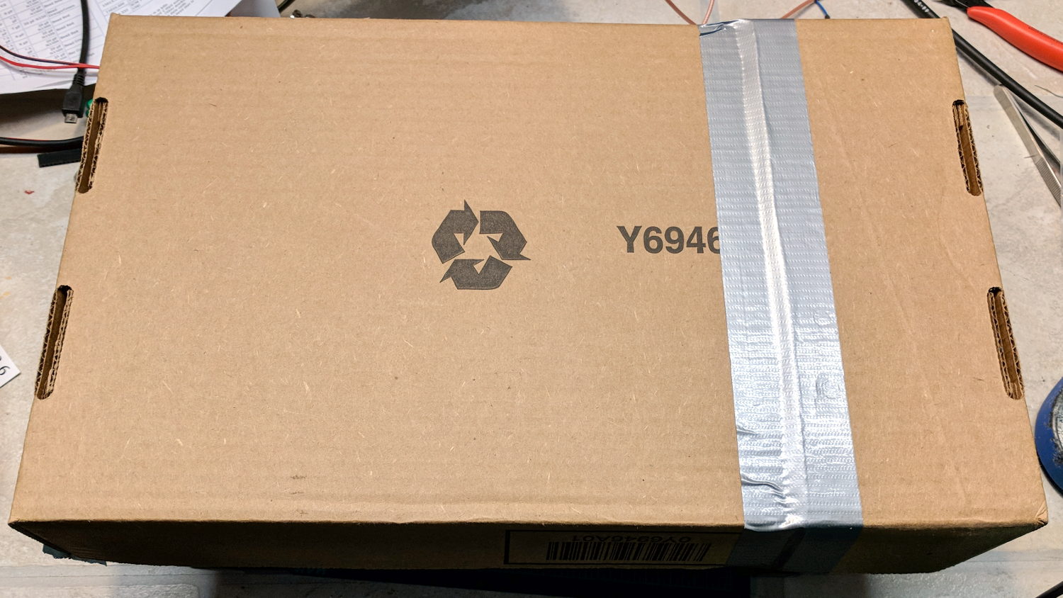
Some surreptitious brush clearing called for a tool larger than our wonderful Fiskars PowerGear pruner, so I unearthed a long-disused bypass lopper in the garage (it may have Come With The House). Alas, the pivot bolt lost its jam nut long ago:
Bypass loppers – OEM 10 mm bolt
That’s an M10x1.5 bolt, for which I lack a corresponding nut.
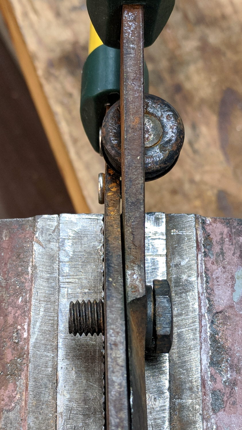
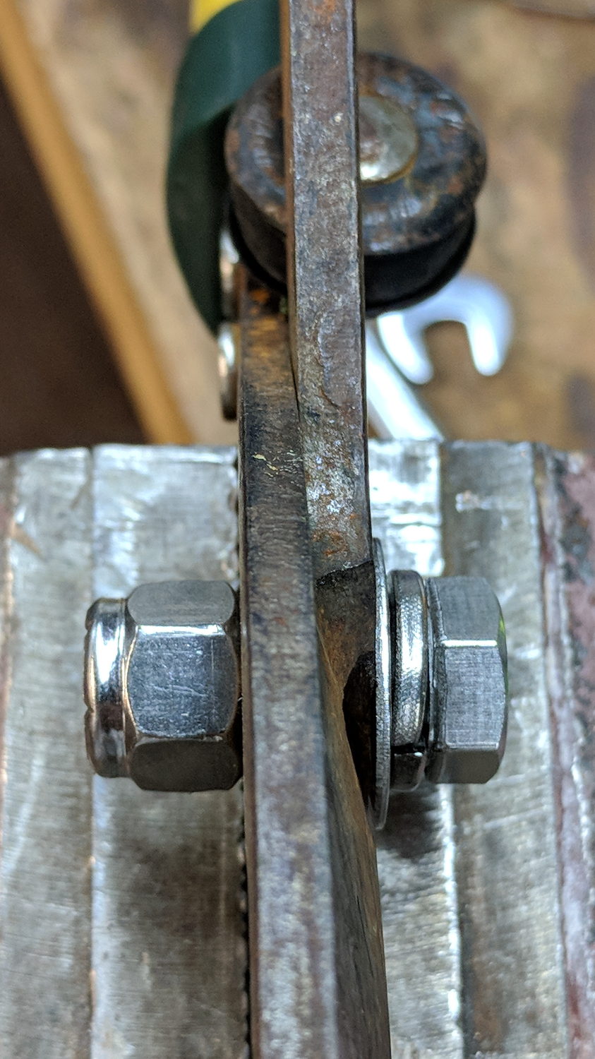
But 3/8-16 is approximately M10x1.5, for small values of thread engagement, and I do have an assortment of inch-sized stainless steel fasteners:
Bypass loppers – 0.375 inch bolt
The nylon lock nut jams the bolt against the left blade, with the split washer applying pressure to the tapered blade. Slobbering oil in the sliding joints restored it to perfect working order.
The weird round dingus on the far side of the pivot, up against the handles, is a bumper cushioning the fully closed position. It’s a nice touch and might work better if its rubber pad hadn’t aged out over the decades spent in the garage waiting for this very day.
It’s my kind of yard work: “What do you need killed next?”
That’s with the card jammed into an Anker USB 3.0 adapter and both devices plugged into the two USB 3.0 “Super Speed” ports in the front of my desktop box. Plugging them both into the adjacent USB 2.0 ports drops the data rate to 18 MB/s.
The Sandisk card claims read-write speeds of “up to” 20 MB/s, so it’s the limiting factor.
Getting reliable performance numbers is surprisingly difficult:
dd bs=4M count=1000 status=progress if=/dev/urandom of=/mnt/part/random.bin
4177526784 bytes (4.2 GB, 3.9 GiB) copied, 214.064 s, 19.5 MB/s
1000+0 records in
1000+0 records out
4194304000 bytes (4.2 GB, 3.9 GiB) copied, 214.922 s, 19.5 MB/s

dd bs=4M count=1000 status=progress if=/dev/urandom of=/mnt/part/random2.bin
4194304000 bytes (4.2 GB, 3.9 GiB) copied, 217.08 s, 19.3 MB/s
1000+0 records in
1000+0 records out
4194304000 bytes (4.2 GB, 3.9 GiB) copied, 217.08 s, 19.3 MB/s
Obviously, prying bits out of the random number generator limits the overall write speed.
Zeros, however, are cheap and readily available:
dd bs=4M count=1000 status=progress if=/dev/zero of=/mnt/part/null.bin
4169138176 bytes (4.2 GB, 3.9 GiB) copied, 23.0091 s, 181 MB/s
1000+0 records in
1000+0 records out
4194304000 bytes (4.2 GB, 3.9 GiB) copied, 23.1775 s, 181 MB/s

dd bs=4M count=1000 status=progress if=/dev/zero of=/mnt/part/null2.bin
4093640704 bytes (4.1 GB, 3.8 GiB) copied, 25.031 s, 164 MB/s
1000+0 records in
1000+0 records out
4194304000 bytes (4.2 GB, 3.9 GiB) copied, 25.7781 s, 163 MB/s
But the caches take a while to drain, even after the command returns:
time ( dd bs=4M count=1000 status=progress if=/dev/zero of=/mnt/part/null3.bin ; sync )
4118806528 bytes (4.1 GB, 3.8 GiB) copied, 23.0004 s, 179 MB/s
1000+0 records in
1000+0 records out
4194304000 bytes (4.2 GB, 3.9 GiB) copied, 23.5305 s, 178 MB/s

real	0m35.887s
user	0m0.008s
sys	0m4.824s
Dividing 4 GB / 35.9 s says the mechanical write speed is close to 110 MB/s.
Reading proceeds a bit faster, while also running up against the effect of the many caches between the spinning platter and the screen:
time ( cp /mnt/part/random.bin /dev/null )
real	0m36.565s
user	0m0.048s
sys	0m1.712s

time ( cp /mnt/part/random.bin /dev/null )
real	0m29.157s
user	0m0.036s
sys	0m1.800s

time ( cp /mnt/part/random.bin /dev/null )
real	0m10.265s
user	0m0.028s
sys	0m1.040s

time ( cp /mnt/part/random.bin /dev/null )
real	0m0.608s
user	0m0.004s
sys	0m0.600s

time ( cp /mnt/part/random.bin /dev/null )
real	0m0.590s
user	0m0.008s
sys	0m0.580s

time ( cp /mnt/part/random2.bin /dev/null )
real	0m31.035s
user	0m0.056s
sys	0m1.816s

time ( cp /mnt/part/random2.bin /dev/null )
real	0m31.024s
user	0m0.052s
sys	0m1.860s
Unsurprisingly, copying a brace of 4 GB files in parallel takes twice as long as each cold-buffer read, so disk’s raw read speed seems to be around 130 MB/s.
The drive’s write speed won’t be the limiting factor while saving camera video data!