Ed Nisley's Blog: Shop notes, electronics, firmware, machinery, 3D printing, laser cuttery, and curiosities. Contents: 100% human thinking, 0% AI slop.
Tag: Improvements
Making the world a better place, one piece at a time
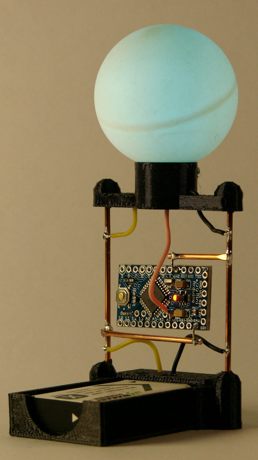
A two-legged spider radome base definitely looks better than the four-legged version:
Arduino Pro Mini – NP-BX1 – radome
The radome base now has a hole punched in its bottom for the data lead, with the two power wires going out the sides as before:
Arduino Pro Mini Battery Holder – SK6812 radome base
The alert reader will notice the vertical strut on the far side doesn’t go directly into the center of its base fitting. I attempted a bit of cosmetic repair on the horizontal wire below the Pro Mini and discovered, not at all to my surprise, (re)soldering a connection to a 14 AWG copper wire an inch away from a 3D printed base doesn’t work well at all.
Doesn’t affect the function and, as nobody will ever notice, I’ll leave it be.
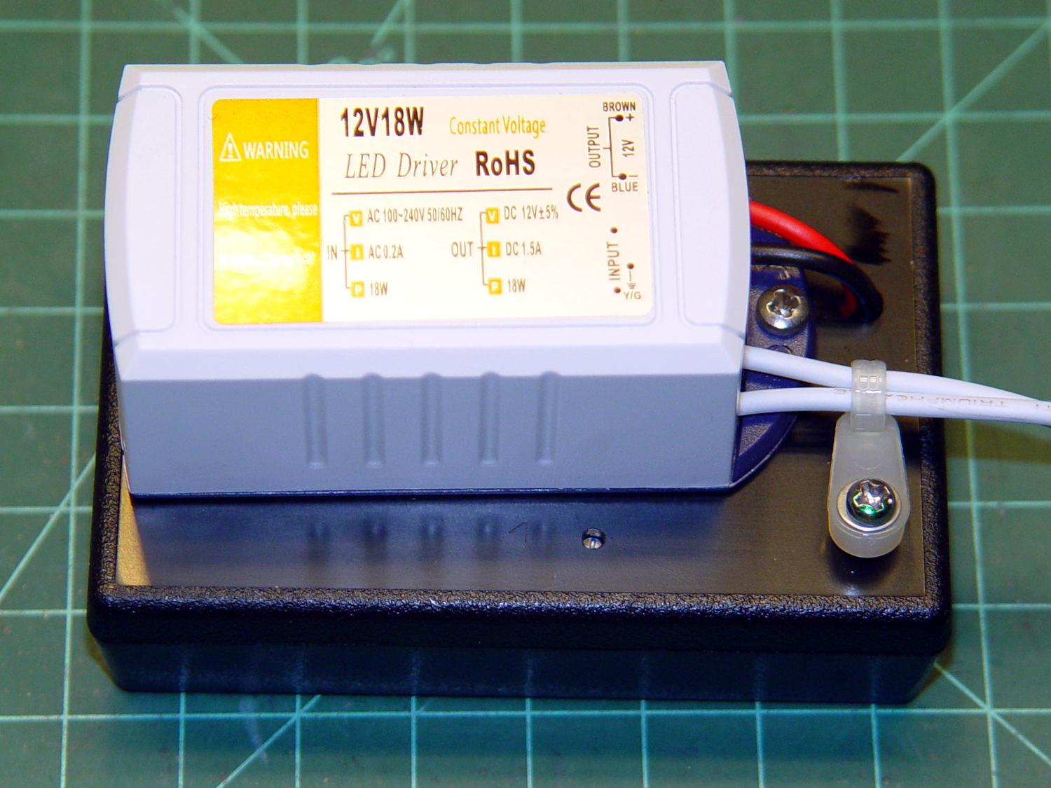
The LEDs connected through a coaxial power jack on the far side of the box, held in place with a generous blob of epoxy:
Needle LEDs power supply – interior
A closer look:
Kenmore 158 COB LED – power supply jack
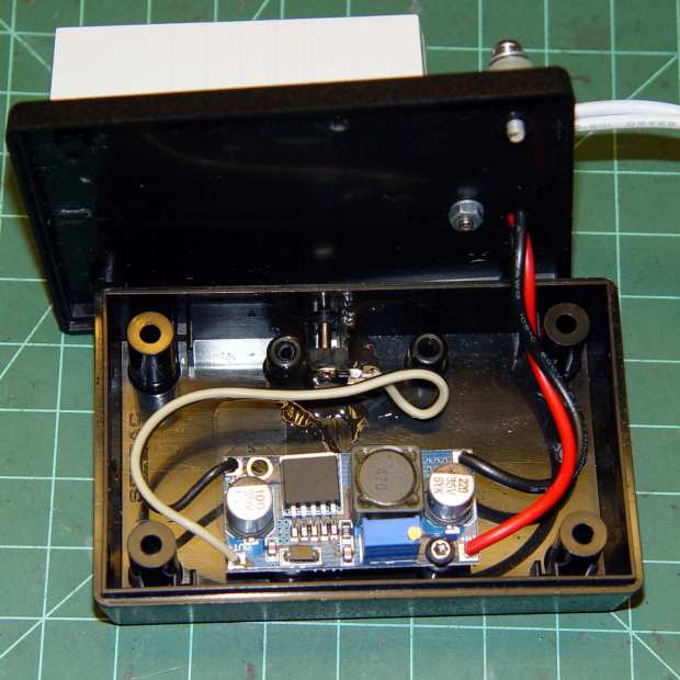
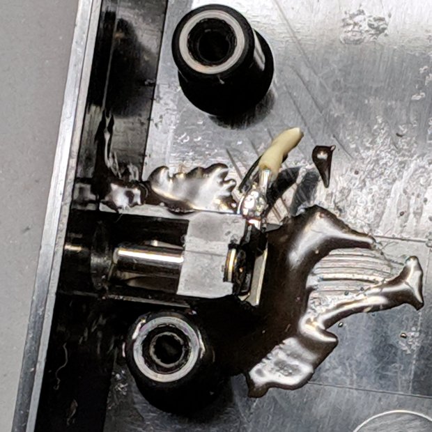
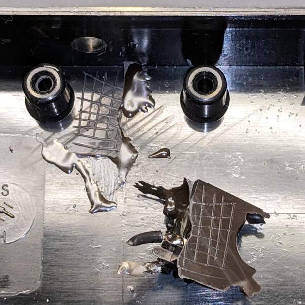
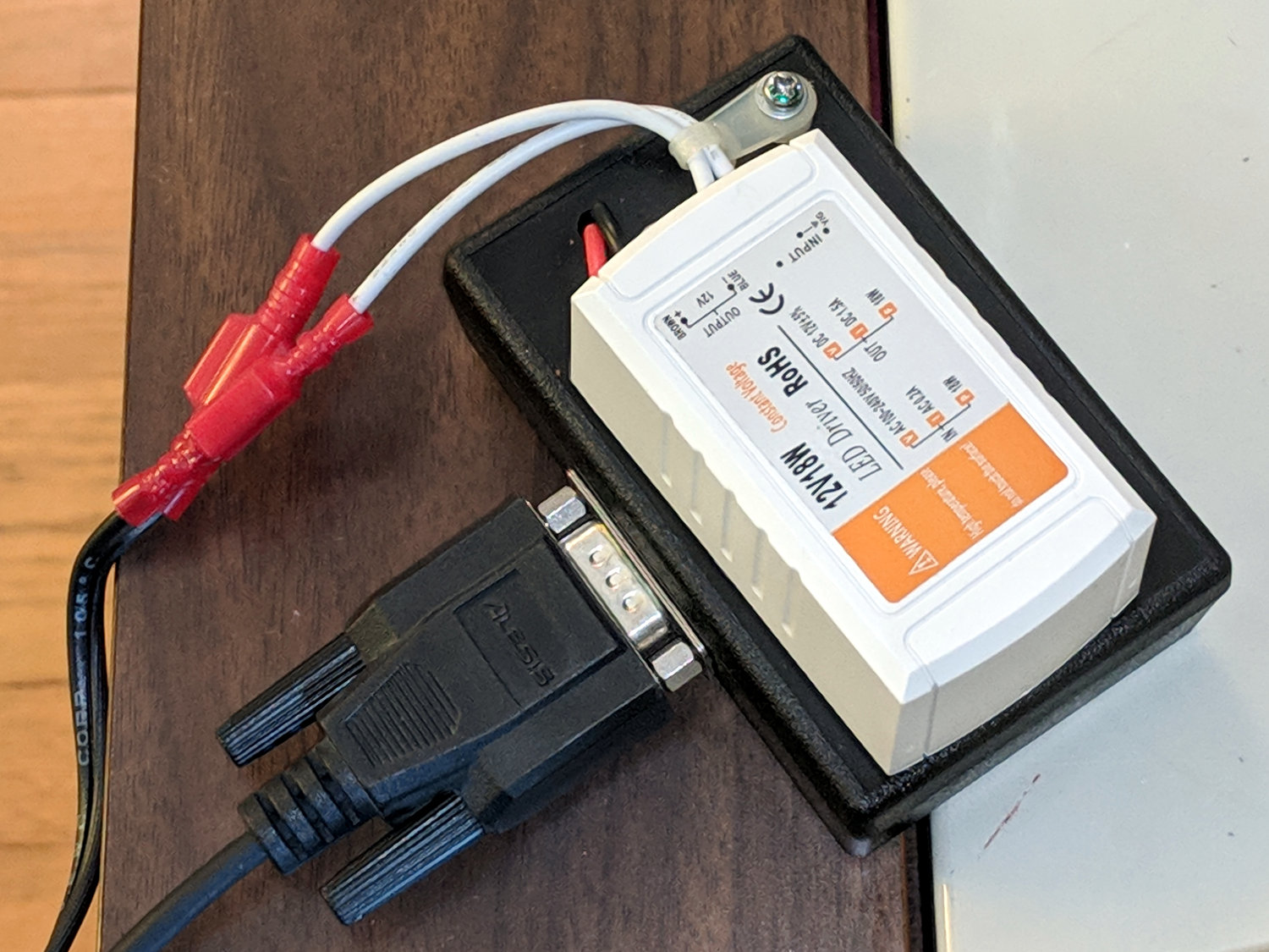
I’m adding a light bar, similar to the one now going onto the Juki TL-2010Q, which needs a direct connection to the 12 VDC supply. Rather than add another coaxial jack, I ripped out the existing jack and installed a DE-9 connector (serial ports being a fading memory by now), giving me an opportunity to test the epoxy joint:
Kenmore 158 COB LED – power supply jack – epoxy bond
Which required grabbing the connector with a pair of pliers and twisting / bending / abusing until it popped free. I don’t know how much grip the scored lines added to the joint, but the connector definitely didn’t give up without a fight; it wasn’t going to fall off on its own.
To be fair, the epoxy had a better grip on the coaxial jack than on the plastic plate, perhaps because the bottom of the jack had all manner of nooks and pins intended for PCB mounting. Ya use what ya got, sez I.
The new connector looks exactly like it should and, because it’s held in place by a pair of screws, should last forever, too:
Continuing the process of silk-purse-izing the DSO150, a batch of USB 1S lithium battery charger modules arrived from halfway around the planet. I drilled & filed a suitable hole / slot / aperture in one of the few remaining spots in the case, then stuck the PCB to the bottom with good foam tape:
DSO150 – USB charger – internal layout
Because the charger includes cell protection circuitry, I replaced the original protected 18650 cell with a bare cell sporting solder tabs. The cell should go directly to the charger board, but the switch disconnects the + wire; I’m unwilling to believe the charger won’t slowly and inexorably discharge the cell if I don’t use the DSO150 for a few months. It could happen.
A label makes the hole look almost professional:
DSO150 – USB charger – Micro-B jack
Well, makes it look Good Enough™, I suppose.
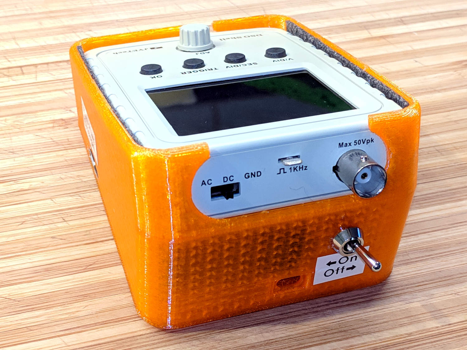
The power switch gets a label, too:
DSO150 – USB charger – battery switch
Flipping the switch ON lights up the scope from the battery.
The charger (sensibly) will not route power from the USB port to the scope without a battery, so you must plug in a USB source with the switch ON, then flip the switch OFF. I don’t know why you’d want to do that, but there you go.
Now it’s a real portable instrument, with all the inconvenience of managing a built-in lithium cell.
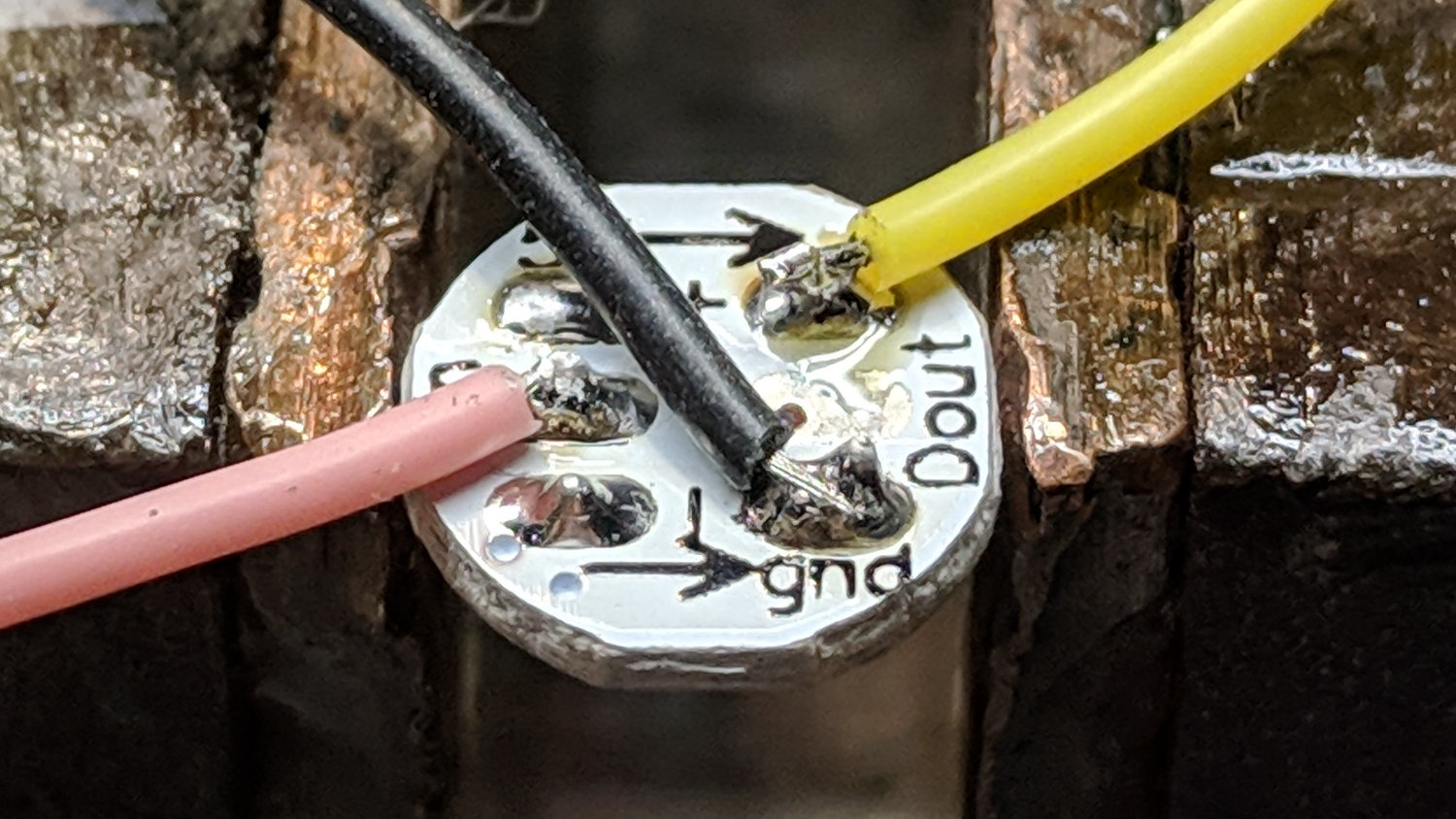
The 3.6 V (and declining) power supply may not produce as much light from the SK6812 LEDs, but it’s entirely adequate for anything other than a well-lit room. The 28 AWG silicone wires require a bit of careful dressing to emerge from the holes in the radome holder:
SK6812 LED PCB – Pirhana holder wiring
The firmware cycles through all the usual colors:
Arduino Pro Mini – NP-BX1 cell – SK6812 – orange phase
A pair of tensilized 22 AWG copper wires support the Pro Mini between the rear struts. The whole affair looks a bit heavier than I expected, though, so I should reduce the spider to a single pair of legs with a third hole in the bottom of the LED recess for the data wire.
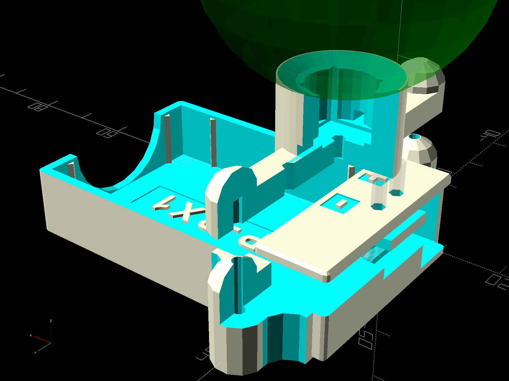
The OpenSCAD source code needs some refactoring and tweaking, but the Pirhana LED solid model version of the battery holder should give you the general idea.
A year or so ago, a certain Young Engineer suggested my Vacuum Tube Lights really needed battery power and rebuffed my feeble objections concerning low LED intensity (3.6-ish V, not plug-in 5 V USB) and short run time (because three constantly lit LEDs draw too much current). Having a spare NP-BX1 holder lying about, here’s a feasibility study:
Arduino Pro Mini – Neopixel – NP-BX1 battery
Not much to it, eh?
Hitching the DSO150 to a Tek current probe (which needs a 50 Ω load, thus the terminator on the BNC tee) seems a clear-cut case of a sow’s ear joining forces with a silk purse:
DSO150 – Arduino Pro Mini – Neopixel current
It was just sitting there, so why not?
Seen with a bit more detail on a better scope:
Ard Mini – NP-BX1 – SK6812 – 10 mA-div
Each vertical increment represents the current into a single LED (at 10 mA/div), with the PWM cycles ticking along at 1.3 kHz.
The current steps aren’t the same height, because the LEDs have different forward voltages. The taller step (at the top) probably comes from the red LED, with the other two being blue and green. The maximum current is only 40 mA, not the 60 mA you’d expect with a 5 V supply.
The PWM width, of course, determines the brightness of each LED. Eyeballometrically, the average current will be half of 40 mA for (just less than) half of each PWM cycle, so figuring each SK6812 module (there’s only one here) will draw 10 mA seems reasonable.
The “base load” from the Arduino looks like 2 mA, so there’s not much point in removing its power and status LEDs.
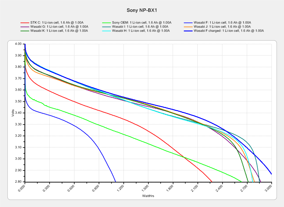
The NP-BX1 lithium cell has lost enough capacity to no longer power my Sony HDR-AS30V helmet camera for at least half of a typical ride. The camera draws around 1 A, so you can clearly see the defunct batteries:
Sony NP-BX1 – 2018-04-24
If the average voltage during discharge is 3.3. V, then a 10 mA load would be 33 mW and a defunct NP-BX1 battery with 2 W·h capacity (at 1 A) might provide 60 hours of continuous use. I’d expect more capacity at lower current, although it’s not clear the cells actually behave that way.
So a battery-powered Vacuum Tube Light might make sense, perhaps as romantic illumination for techie snuggling:
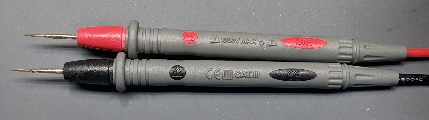
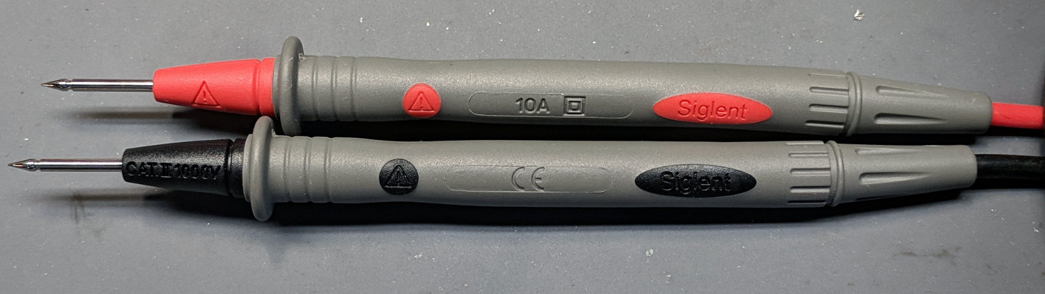
The needle-tip probes carry a 20 A current rating:
No-Name DMM probes – needle tip – 20 A
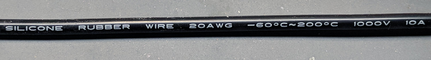
If you look out along the wire, though, you’ll find a 10 A rating:
No-Name DMM probes – needle tip – 10 A wires
Now, even though 20 AWG wire in silicone may carry a 17 A spec, the corresponding 200 °C temperature seems excessive for a test probe. Limiting the current to 10 A would reduce the power dissipation by two thirds, which should limit the temperature rise. Whether the wire actually contains 20 AWG of actual copper strands remains an open question.
The kit also had banana plug / test hooks with no particular rating, although the wire allegedly has 16 AWG conductors:
DMM Clip Leads – 16 AWG
The banana plug / alligator clip combo claims 30 A, also with 16 AWG conductors. Who knows? It could be true.
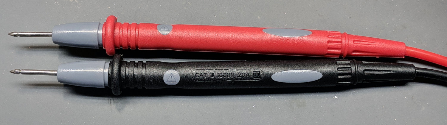
The probes carry a 10 A rating and, although the wires aren’t branded, I’ll assume they have good-enough QC to ensure the copper matches the claims. The production values seem a bit higher, too, even if they bear a striking resemblance to the cheap probes.
And, for reference, the probes with the cold solder joint also claim 20 A:
No-Name DMM probes – 20 A
Wouldn’t trust any of ’em for more than a few amps, tops …
Sony tried, they really tried, to make their proprietary Memory Stick flash memory cards catch on, but the slot in their HDR-AS30V Action / Helmet camera accepts both Memory Stick Micro and MicroSD cards. The two cards have slightly different sizes, the AS30V’s dual-purpose slot allows MicroSD cards to sit misaligned with the contacts, and the camera frequently kvetches about having no card.
The only solution seemed to be starting the camera while watching the display to ensure the card worked, but it would sometimes joggle out of position during a ride.
I cut out a tiny polypropylene rectangle(-ish) spacer to fill the Memory Stick side of the slot, sized to fit between the spring fingers holding the MicroSD card against its contacts:
Sony HDR-AS30V Camera – MicroSD card and spacer
Not the best cutting job I’ve ever done, but it was an iterative process and that’s where I stopped. If this works and I have need for another / better spacer, I promise to do better.
The spacer’s somewhat mottled appearance comes from tapeless sticky (an adhesive layer on a peel-off backing: inverse tape!) applied to the top side, which will affix it to the slot. I’d rather glue the spacer to the MicroSD card, but then the card wouldn’t fit in the USB 3.0 adapter I use to transfer the files.
The chips along the left edge of silkscreen come from my fingernail, because pressing exactly there seems to be the best way to force the damn thing into the proper alignment.
So the slot + spacer looks like this:
Sony HDR-AS30V Camera – dual-card slot with spacer
The MicroSD card fits in the far side of the slot, facing toward you with contacts downward, thusly:
Sony HDR-AS30V Camera – MicroSD card with spacer
And then It Just Works™, at least on the very few rides we’ve gotten in during December and early January.
Incidentally, the blue and exceedingly thin latch finger holding the battery in place will snap, should you drop the camera on its non-lens end from any height. Conversely, should you drop it on the lens end, you can kiss the optics goodbye. Your choice.