Ed Nisley's Blog: Shop notes, electronics, firmware, machinery, 3D printing, laser cuttery, and curiosities. Contents: 100% human thinking, 0% AI slop.
Tag: Improvements
Making the world a better place, one piece at a time
We’ll be tackling several long-delayed household projects during the next month. As a consequence, I won’t be doing my usual techie tinkering and will post shop notes only occasionally.
There’s not much to say about scraping, priming, and repainting, other than that it’s an ugly job which must get done!
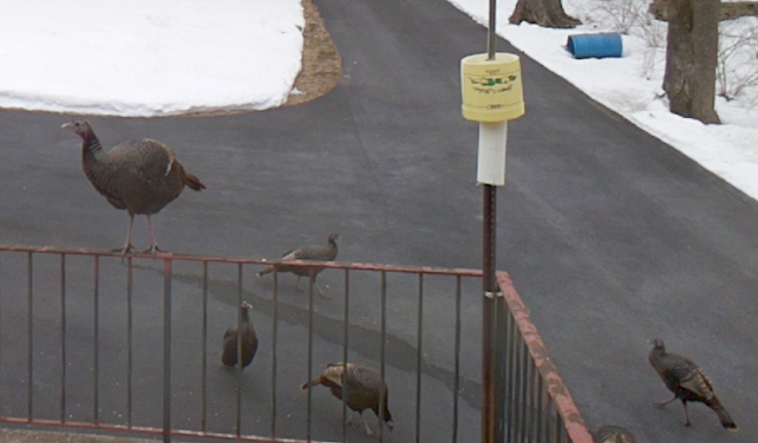
Turkey on patio rail
If only we could train the turkeys to scrape the rail …
The config/hostname.conf file (found under /system/sdcard/when the camera is running) file defines the camera’s name:
Cam4
That file overrides the contents of the usual etc/hostname.conf file, somewhat to my surprise, which remains the default Ingenic-uc1_1.
The bin/hostname utility returns the hostname:
[root@Cam4 ~]# which hostname
/bin/hostname
[root@Cam4 ~]# hostname
Cam4
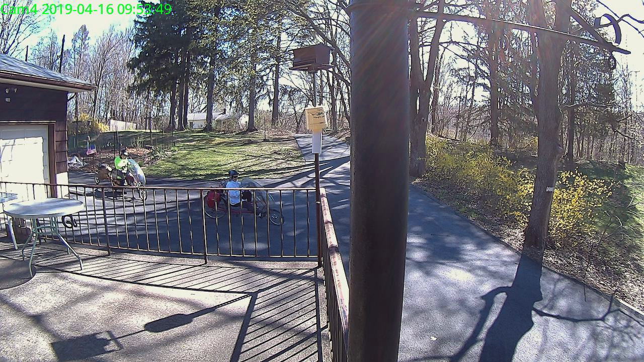
You can automagically get the hostname in the on-screen display by modifying the OSD formatting variable in config/osd.conf:
OSD="$(/bin/hostname) %Y-%m-%d %H:%M:%S"
Which works because the main OSD script sources the config file to set the variable:
Xiaomi Dafang – 15-04-2019_13.26.18
It’s also helpful (at least for my purposes) to add the hostname to the image filenames. A one-line tweak in the scripts/detectionOn.sh script does the trick:
The ESR02 reports one as a 4.8 µF capacitor, the other as a “defective part” with a 4 kΩ resistance. Having a cap fail by turning into a resistor is surprising; I’m more surprised it didn’t simply burn up.
After I finish fiddling with the first camera, I’ll copy its card onto these four, unique-ify the IP addresses / hostnames /suchlike, and bring ’em all online.
Given a camera running Xiaomi Dafang Hacks software, you can set up motion-triggered image capture and save the images either locally or on an FTP server. The latter makes sense, as it automatically plunks the images where they’re more generally available.
Define the FTP server parameters in config/motion.conf:
The FTP server should have the Cam4 directory in place and shared for read-write access before attempting to plunk files therein. Ahem.
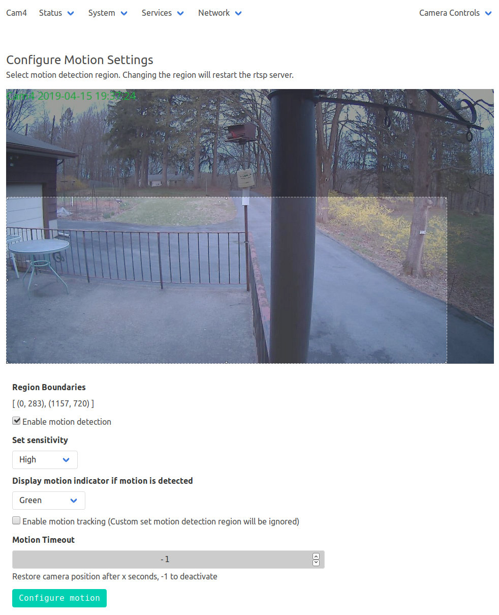
The camera’s Services menu leads to the motion configuration page:
Xiaomi Dafang – Motion Settings page
Limiting the detection region to the lower-left corner cuts out all the waving-in-the-breeze foliage in the yard, while covering the driveway. High sensitivity detects squirrel-sized objects in the foreground, although your mileage will certainly differ.
The camera seems rate-limited at 5 s/image, which may come from FTP transfer overhead; I don’t know if the code includes a built-in delay or if it just works like that. The NAS drive requires upwards of 7 s to spin up if it hasn’t been used for a while, but afterwards the transfers don’t take that long.
Mounting the NAS drive’s CIFS shared directory from my desktop PC works as before:
sudo mount -v -o rw,credentials=/root/.nas-id,vers=1.0,uid=ed -t cifs //192.168.1.10/Cam4 /mnt/part
Then view / edit / delete images as needed:
Xiaomi Dafang – IR motion capture – 15-04-2019_20.02.06
The camera has built-in IR LEDs, but they’re nowhere near powerful enough to illuminate the entire yard.
# Interval between snaps, in seconds
TIMELAPSE_INTERVAL=10
# Duration of the script should run, in minutes, set to 0 for unlimited
TIMELAPSE_DURATION=60
# Save dir config
SAVE_DIR_PER_DAY=1
# Enable compression
COMPRESSION_QUALITY=100
The images, named along the lines of 13-04-2019_191810_001.jpg, appear in the DCIM/timelapse directory, tucked into daily directories with names like 2019-04-13, a mismatch obviously in need of tweaking. There’s also a time_lapse directory which seems like cruft from an earlier revision; you can configure the target directory in scripts/timelapse.sh.
Start the script manually or from a crontab entry, wait until it’s done, then transfer the images to somewhere more convenient with a Bash one-liner:
The -s silences all curl output; omit it until you’re sure the lashup works as you expect. I always forget the backslash before the semicolon terminating the -exec command.
The -n pulls the userID and password from the ~/.netrc file you previously set up for manual ftp sessions:
The IP address corresponds to my ancient NAS drive; your mileage may vary.
From my desktop box, mount the NAS drive:
sudo mount -t cifs -o "credentials=/root/.nas-id,vers=1.0,uid=ed" "//nasty/Timelapse" /mnt/part
The drive’s credentials aren’t particularly secret, but tucking them into /root/.nas-id means you could automount the drive with no hassle. The NAS drive requires the oldest possible CIFS version, of course.
Then view the pix:
Xiaomi Dafang – 15-04-2019_13.26.18
You could set up the camera as an NFS share, but having all the cameras deposit their pix in a common location seems more convenient, particularly after I get around to automating the image transfer. Regrettably, the NAS drive doesn’t support subdirectories.