Ed Nisley's Blog: Shop notes, electronics, firmware, machinery, 3D printing, laser cuttery, and curiosities. Contents: 100% human thinking, 0% AI slop.
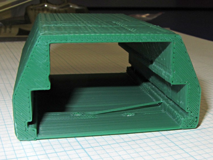
Unlike the previous kludge, this GPS interface case resembles an extrusion with the PCBs sliding into place, held by setscrews along the edges of the slots:
HT-GPS Adapter Case – end view
Those errant threads seem to arise from not quite bonding to the corner. The battery side of the case (bottom in this view) is one thread wide, which isn’t quite enough. Adding another thread makes it 1 mm wide, which seems excessive.
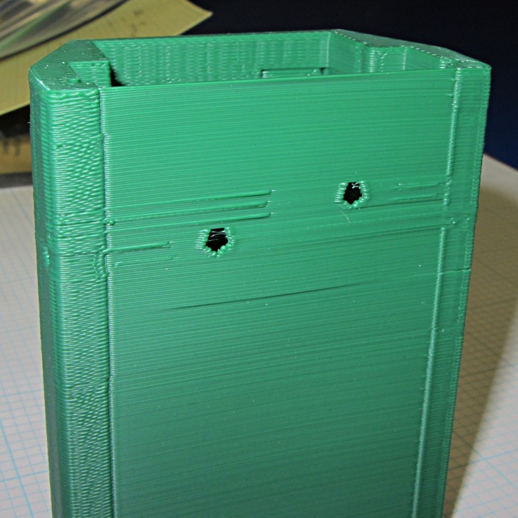
The idea was to glue the battery interface plate on that side, but printing the case vertically puts various flaws along that surface:
HT-GPS Adapter Case – bottom view
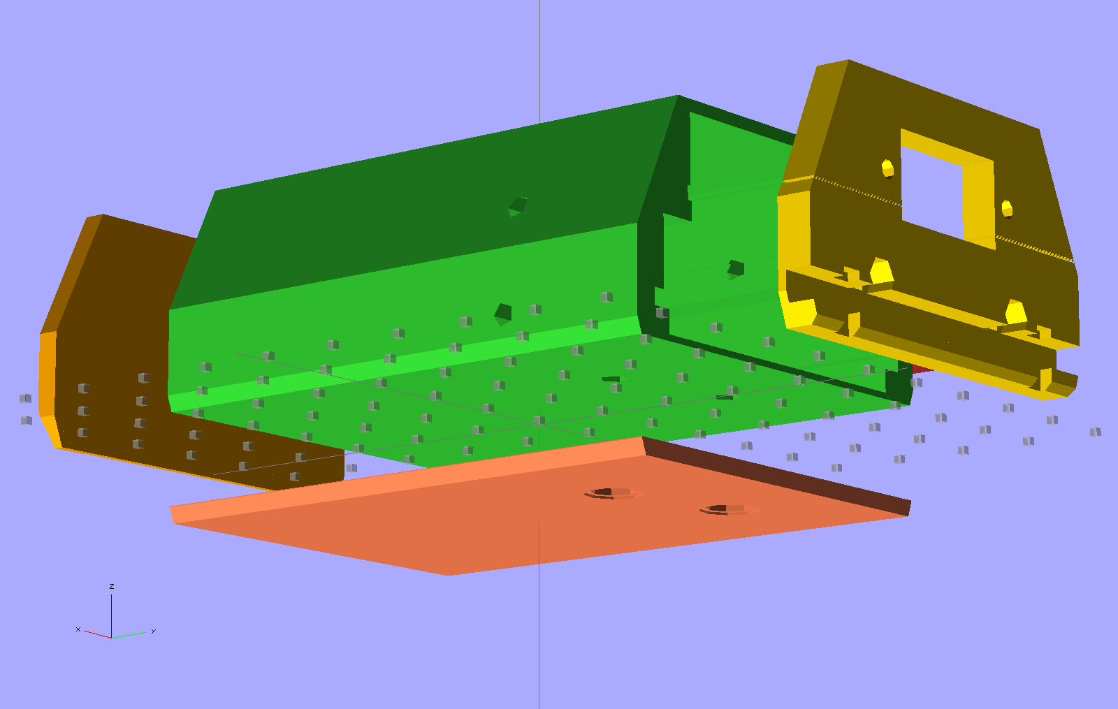
So the next iteration will merge the battery plate with the case and print the whole affair in one shot. This view shows all the parts separately:
HT-GPS Adapter Case – exploded bottom view
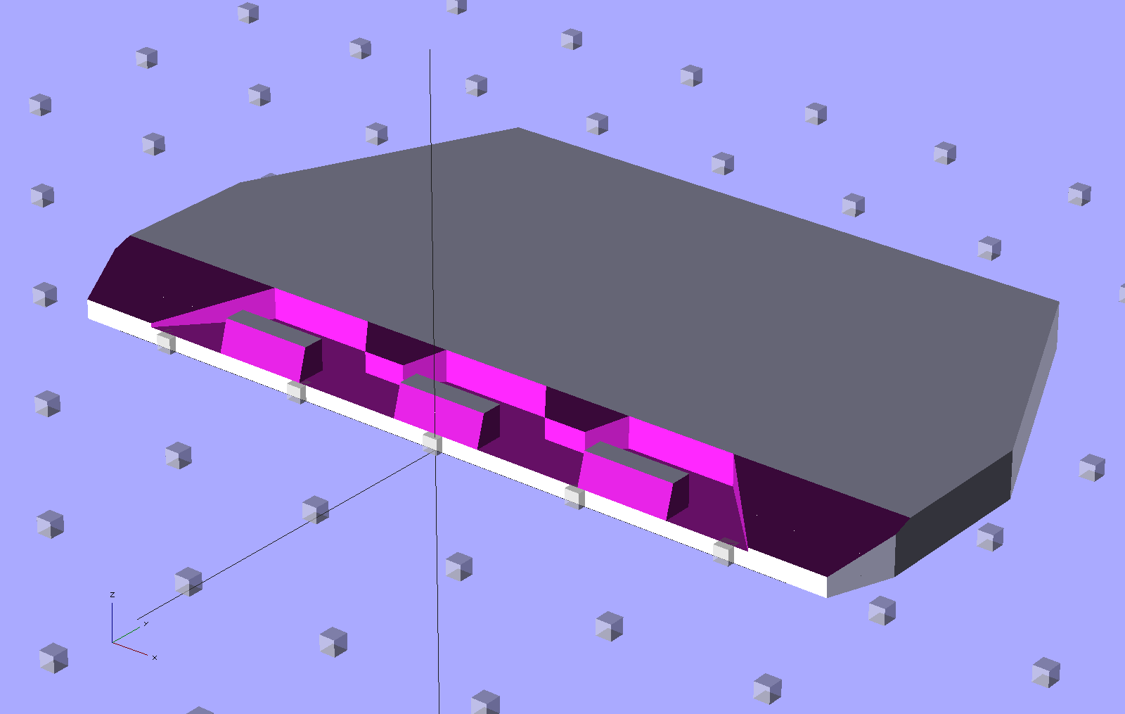
This shows the case joined with the battery plate, neatly aligned for printing:
HT-GPS Adapter Case – combined battery interface
The battery plate has a 0.1 mm extension into the case to avoid problems from objects with coincident planes. Unfortunately, however, that means the intersection between the base plate and the shell forms a line with three planes extending from it: the two outside walls (which are co-planar) and the plate extension inside the case. Skeinforge sometimes complains mightily about that, despite my having applied a union() to fuse the plate with the case: obviously I don’t quite understand how union() works.
I think the battery contact holes will come out close enough to being right; they all have points on the top edge to reduce the overhang problem.
One gotcha: the actual metallic contact studs for the battery. The contacts for the ICOM IC-Z1A case came from carefully shaped brass screws secured by nuts above the PCB and that’s what I’ve been designing around for this case. Unfortunately, the PCB must slide in before installing the studs, which means reaching into the depths of the case, with all the wiring in the way, to turn those nuts. Fortunately, the PCB has plenty of clearance in that direction, but … it’ll be awkward at best.
The studs also need a slot / socket / dingus to prevent rotation while tightening the nuts; right now the contact plate is circular-ish, but maybe I should rethink that.
The Wouxun KG-UV3D radio has two lugs inside the battery compartment:
Wouxun KG-UV3D – battery lugs
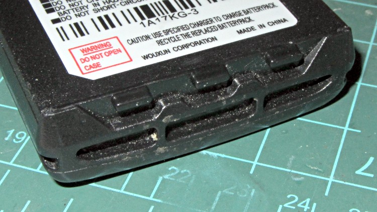
The battery packs and DC adapters all have clever spring-steel latches that engage those lugs, with a pair of sliding buttons that depress the ends of the spring to release the pack:
Wouxun KG-UV3D – battery pack latch
That mechanism may be cheap, straightforward, and easy to build in mass production, but I can’t figure out how to duplicate it for a case to house the GPS+Voice interface circuitry. That box had the dual disadvantages of being plug-ugly and not locking to the radio, but it did help establish some key dimensions, which is not to be sniffed at.
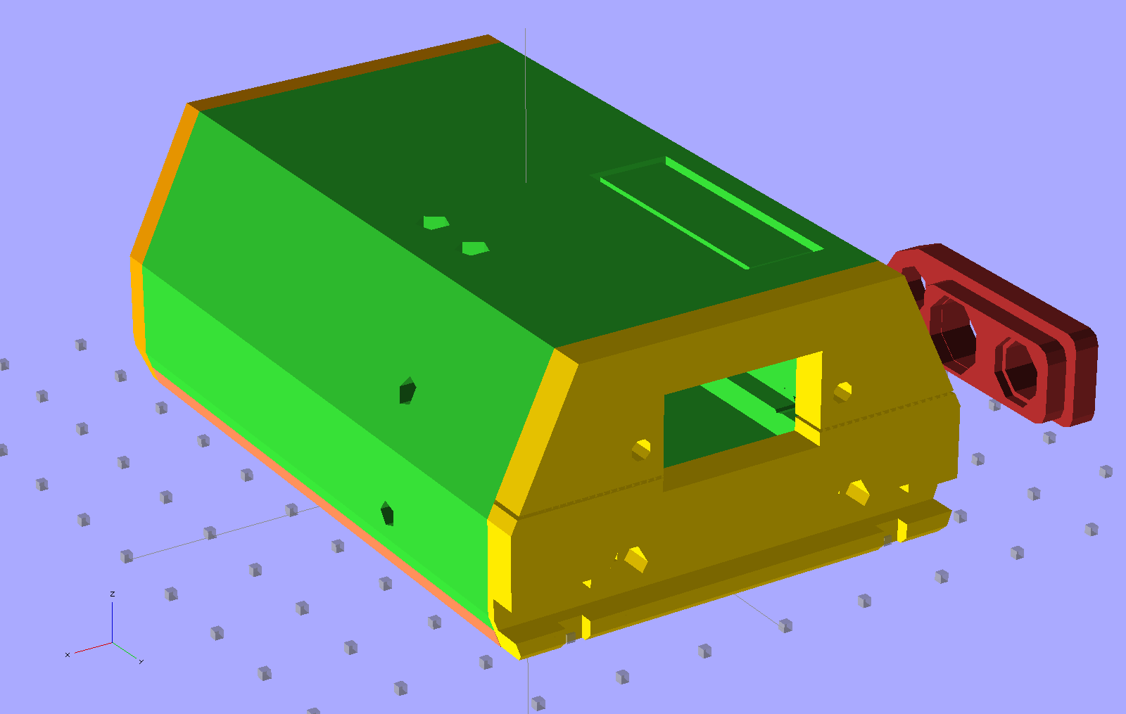
A bit of heads-down effort produced this not-so-hideous printable case:
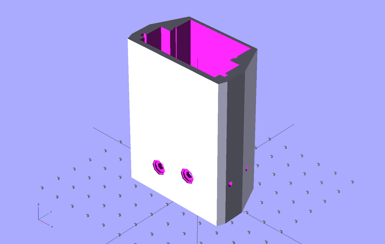
HT-GPS Adapter Case – Overview
The rectangle on the top is a built-in support structure for what will be a window over the four LEDs on the Byonics TinyTrak3+ board. The two holes on the top allow screwdriver access to the TT3 trimpots, although they might not be necessary. The four holes (two visible) along the sides fit 4-40 setscrews that lock the PCBs into slots along the inside of the main case body. The red doodad off to the far side is that plug alignment block for the radio.
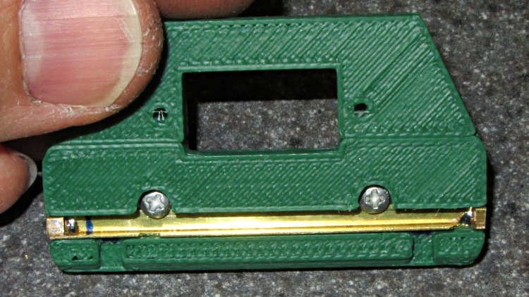
The yellow latch plate on the end engages the lugs with a bar sliding in a slot, which looks like this when it’s locked:
HT-GPS Case Latch – locked
A view from the top side shows the notches that release the lugs:
HT-GPS Case Latch – detail
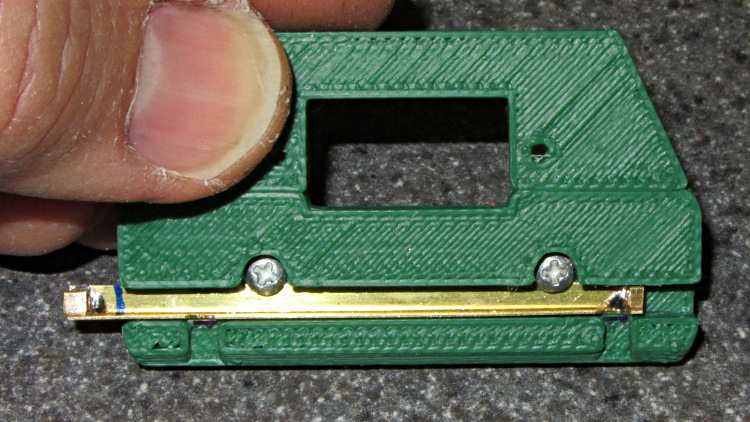
In the unlocked position the notches and lug slots line up:
HT-GPS Case Latch – open
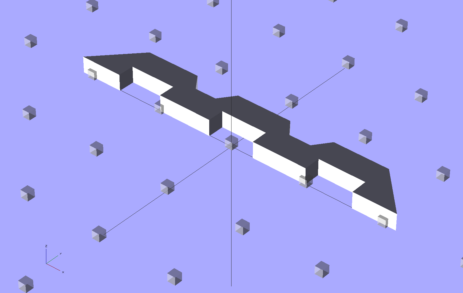
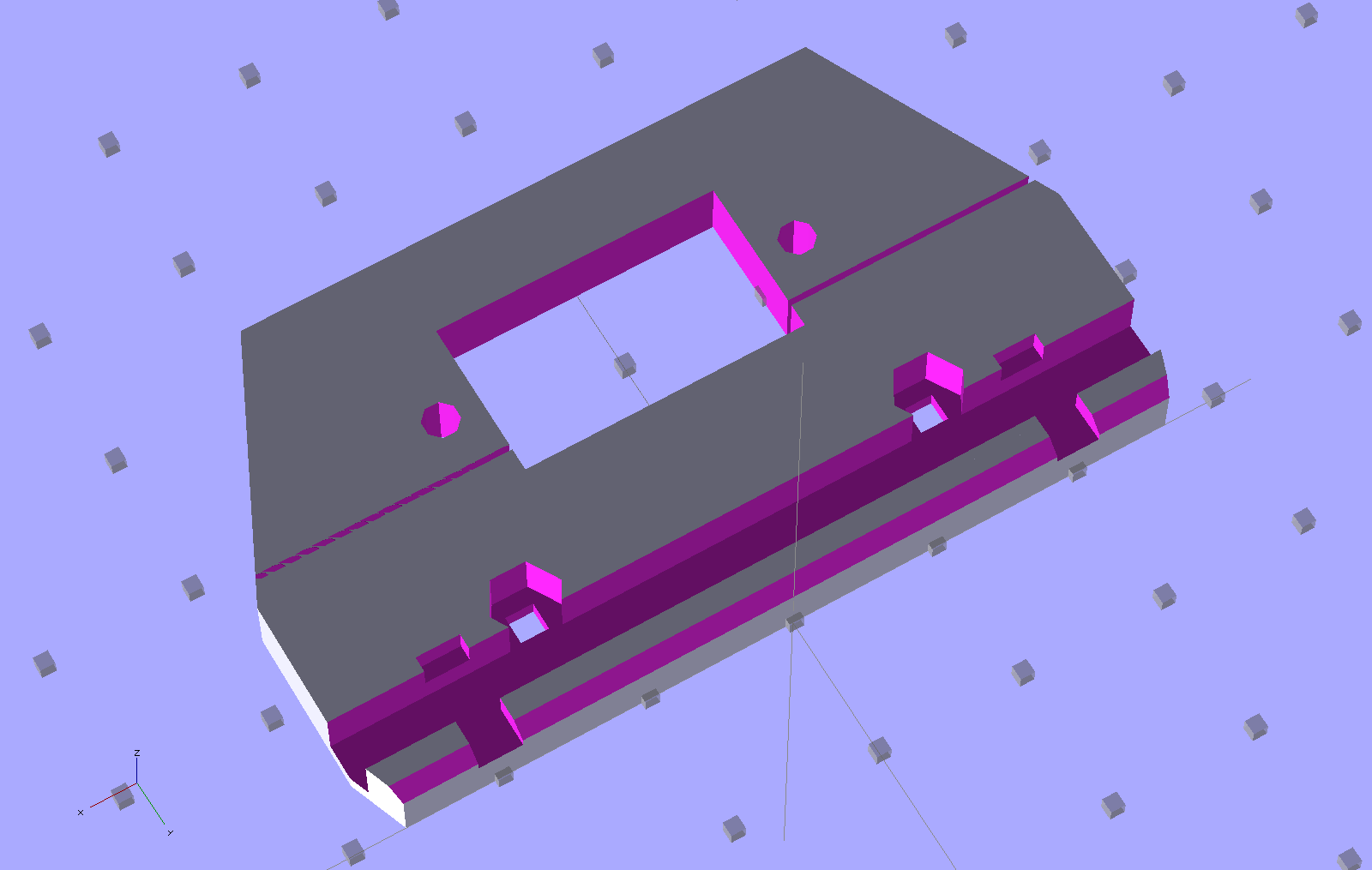
The solid model shows the plastic structure, which is slightly improved from the pictures:
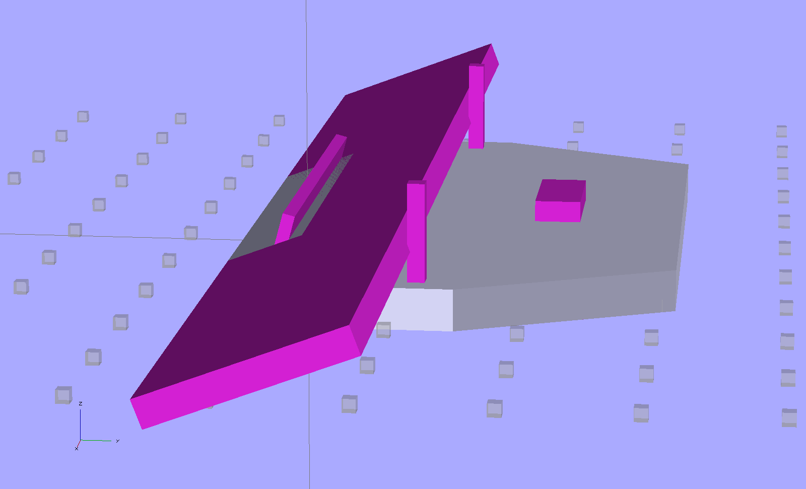
HT-GPS Case – latch and connector plate
The big hole fits around the TinyTrak3+ serial connector to the GPS receiver. The slot across the hole splits the plate so it can fit around the already-soldered connector.
The latch bar consists of a L-shaped brass angle (from the Big Bag o’ Cutoffs) with two snippets of square brass tube soldered to the ends:
HT-GPS Case Latch – bar detail
I cut the angle to length with a Dremel abrasive wheel, soldered two brass tubes, sliced them off with a Dremel cutoff saw, roughed out the slots with the abrasive wheel, and applied some tool-and-die maker’s (aka needle) files to smooth things out. Yup, had to clamp each soldered joint in a toolmaker’s vise to keep from melting it during the nastier parts of that process. A pair of 2-56 screws, with nuts behind the plate, hold the bar in place and provide some friction.
Moving the latch bar requires poking the end with a sharp object (captured by the brass tubing), because I couldn’t figure out how to put finger-friendly buttons on it. This would be completely unusable for an actual battery, but should work OK for a permanently mounted GPS interface.
Conspicuous by their absence:
Holes in the case for the cables (may need more surface area on the ends)
Any way to fasten the latch plate to the main case (I may just drill holes for small pins)
Provision for the TT3 mode switch
A cover for the exposed radio chassis above the latch lugs (may be a separate shell glued to the latch plate)
The whole thing needs a full-up test to verify the serial connector clears the back of the case…
The Peltier assembly looked like this while I was epoxying everything together with JB Weld:
Peltier module – epoxy curing
The aluminum-case resistor held the heatsink at 105 °F to encourage the epoxy to cure in a finite amount of time.
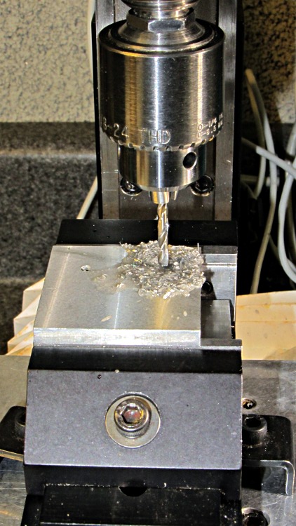
The 40 mm square block is a squared-up piece of 1/2 inch aluminum plate (manual CNC on the Sherline, nothing fancy) with a pair of 6-32 tapped holes for the screws that will hold TO-220 transistors or the yet-to-be-built TO-92 adapter. The CPU heatsink got a pair of symmetric holes for the posts holding it to the acrylic base, but other than that it’s perfectly stock.
MOSFET thermal block – drilling
Then epoxy the thermistor brick to the middle of the block between the two screws, stick on some obligatory Kapton tape to prevent embarrassing short circuits, and add a foam collar around the Peltier module to insulate the block from the heatsink:
MOSFET thermal block
A square foam shako covers everything, held down with a random chunk o’ weighty stuff, to insulate the whole affair from the world at large.
This one came out surprisingly well, apart from the total faceplant with that resistor. With any luck, it’ll measure MOSFET on-state drain resistance over temperature for an upcoming Circuit Cellar column; it’s a honkin’ big Arduino shield, of course.
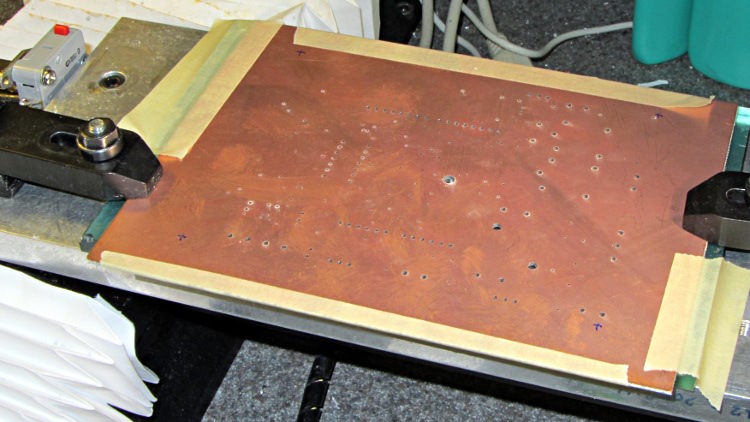
I think I can epoxy the resistor kinda-sorta in the right spot without having to drill through the PCB into the traces. Maybe nobody will notice?
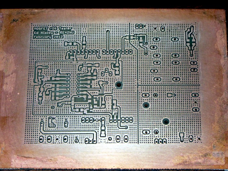
The traces came out fairly well, although I had to do both the top and bottom toner transfer step twice to get good adhesion. Sometimes it works, sometimes it doesn’t, and I can’t pin down any meaningful differences in the process.
And it really does have four distinct ground planes. The upper right carries 8 A PWM Peltier current, the lower right has 3 A drain current, the rectangle in the middle is the analog op-amp circuitry tied to the Analog common, and surrounding that is the usual Arduino bouncy digital ground stuff. The fact that Analog common merges with digital ground on the Arduino PCB is just the way it is…
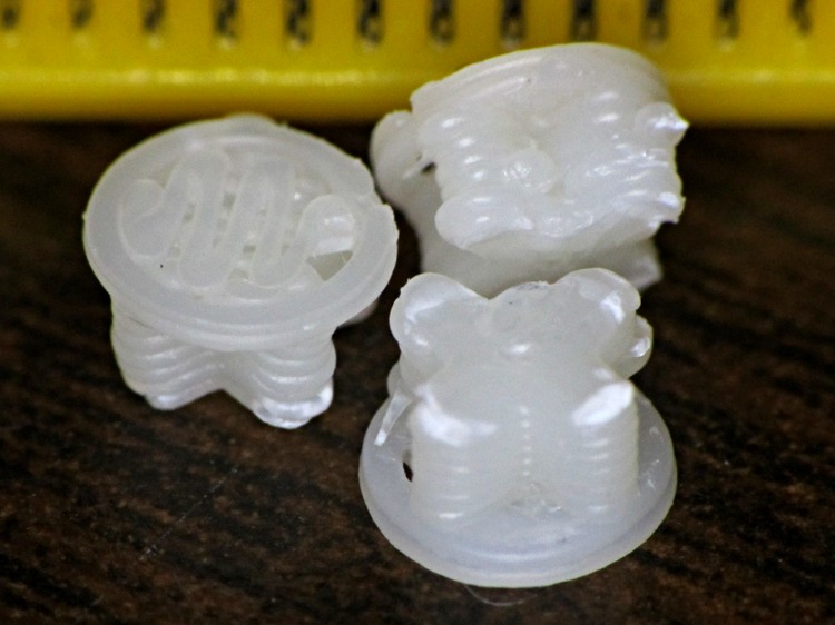
Having printed up three of those handles for Show-n-Tell, I preemptively installed one in the hasn’t-failed-yet clamp, and poked the support out of another to show how it works. They’re just the cutest little buttons:
HF bar clamp handle – support plug
The fins are a touch under 4.5 mm end-to-end and 1 mm (2 × 0.5 mm) across, with layer thickness = 0.25 mm. The first layer fill looks a bit lackadaisical, but the bottom of the surrounding handle came out glass-solid with barely visible joints between the threads, so the settings work fine for larger objects.
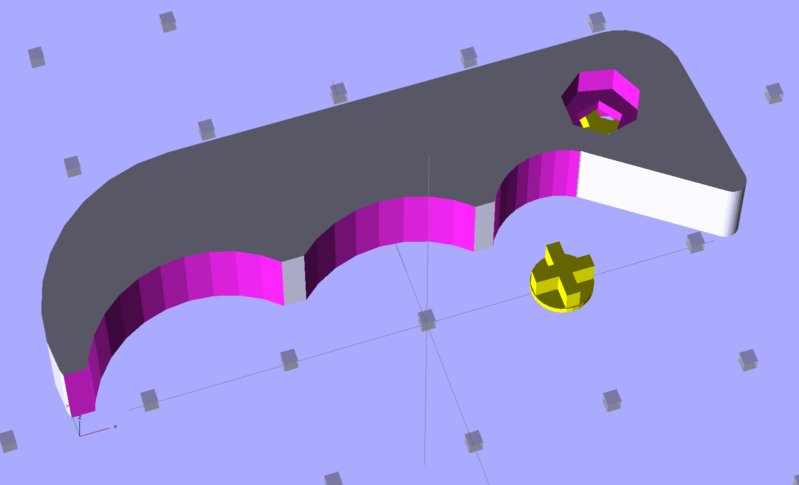
HF Bar Clamp – support – solid model
The tip of each fin has a scar where the overlying perimeter thread bonded to it. Skeinforge is set to extrude the perimeter first, which would squirt that circle (well, pentagon) into mid-air… which is why this support plug lies in wait below.