Ed Nisley's Blog: Shop notes, electronics, firmware, machinery, 3D printing, laser cuttery, and curiosities. Contents: 100% human thinking, 0% AI slop.
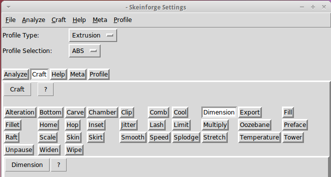
The Skeinforge Craft window presents a formidable array of buttons, one for each possible plugin:
Skeinforge standard
I’ve disabled many of those plugins because, for example, limiting Z-axis speed isn’t relevant on my printer. If you’re sure you won’t use some of the plugins, remove them by editing /where-it's-installed/skeinforge_application/skeinforge_plugins/profile_plugins/extrusion.py thusly…
In getCraftSequence(), located at about the midpoint of that file, duplicate the line that lists the plugins and add an octothorpe (OK, a hash) to make one line a Python comment, then remove the plugins you don’t care about from the other line:
def getCraftSequence():
	'Get the extrusion craft sequence.'
#	return 'carve scale bottom preface widen inset fill multiply speed temperature raft skirt chamber tower jitter clip smooth stretch skin comb cool hop wipe oozebane splodge home lash fillet limit unpause dimension alteration export'.split()
	return 'carve scale preface inset fill multiply speed temperature raft skirt jitter clip smooth skin cool dimension alteration export'.split()
This being Python, do not change the indentation. If you get overenthusiastic and toss something useful overboard or just pine for the Good Old Days, swap the octothorpe to your modified line to restore the original plugin assortment.
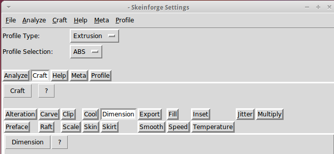
Save the result and you’ll see only the useful buttons:
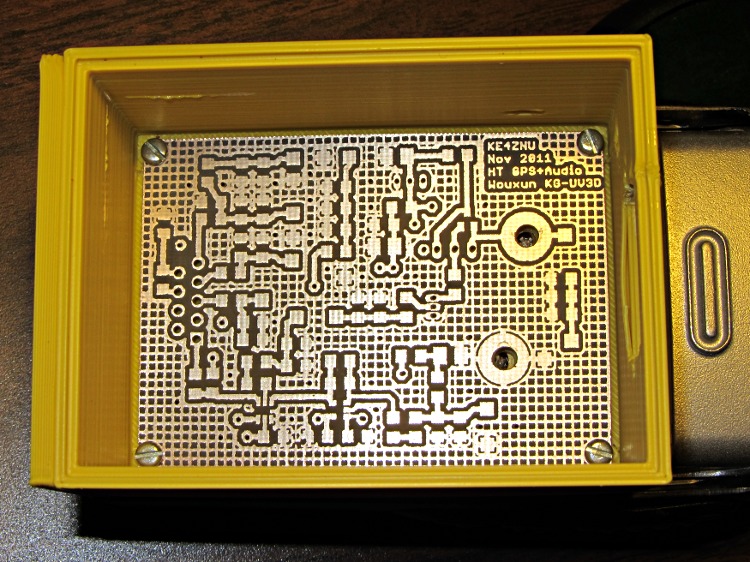
It always feels good when the parts fit together, even if they don’t actually do anything yet…
Bare PCB in Wouxun HT battery case
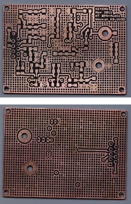
That’s the bare PCB in the first-pass 3D-printed battery case adapter, both of which need quite a bit more work. In particular, the case desperately needs some sort of latch to hold the yet-to-be-built contacts against the HT’s battery terminals.
Amazingly, all the holes lined up spot on, although I think the lower battery contact could move half a millimeter closer to the base of the radio. The battery case contacts are large enough to work as-is and, for what it’s worth, the Wouxun battery cases seem to differ slightly among themselves, too.
The circuit has provision for pairs of SMD caps on all the inputs, with which I hope to squash RFI from both the VHF and UHF amateur bands by choosing their self-resonant frequencies appropriately.
Edit: You may prefer my Kicad-to-HAL converter, which produces HAL files from carefully crafted Kicad schematics.
Herewith, the script that you’ll apply to schematics built with parts from the hal-config-2.4.lbr.odt library (which you must rename to get ride of the ODT extension):
/******************************************************************************
* HAL-Configurator
*
* Author: Martin Schoeneck 2008
* Additional gates and tweaks: Ed Nisley KE4ZNU 2010
*****************************************************************************/
#usage "<h1>HAL-Configurator</h1>Start from a Schematic where symbols from hal-config.lbr are used!";

string output_path =    "./";
string dev_loadrt =     "LOADRT";
string dev_loadusr =    "LOADUSR";
string dev_thread =     "THREAD";
string dev_parameter =  "PARAMETER";

string dev_names[] = {
"CONSTANT",								// must be first entry to make set_constants() work
"ABS",				// 2.4
"AND2",
"BLEND",			// 2.4
"CHARGE-PUMP",		// 2.4
"COMP",
"CONV_S32_FLOAT",	// 2.4
"DDT",				// 2.4
"DEADZONE",			// 2.4
"DEBOUNCE",			// 2.4
"EDGE",
"ENCODER",			// 2.4
"ENCODER-RATIO",	// 2.4
"ESTOP-LATCH",
"FLIPFLOP",
"FREQGEN",			// 2.4
"LOWPASS",
"MULT2",			// 2.4
"MUX2",
"MUX4",				// 2.4
"MUX8",				// 2.4
"NEAR",				// 2.4
"NOT",
"ONESHOT",
"OR2",
"SAMPLER",			// 2.4
"SCALE",			// 2.4
"SELECT8",			// 2.4
"SUM2",
"TIMEDELAY",		// 2.4
"TOGGLE",			// 2.4
"WCOMP",			// 2.4
"XOR2",				// 2.4
""					// end flag
};

/*******************************************************************************
* Global Stuff
******************************************************************************/

string FileName;
string ProjectPath;
string ProjectName;

void Info(string Message) {
dlgMessageBox(";<b>Info</b><p>\n" + Message);
}

void Warn(string Message) {
dlgMessageBox("!<b>Warning</b><p>\n" + Message + "<p>see usage");
}

void Error(string Message) {
dlgMessageBox(":<hr><b>Error</b><p>\n" + Message + "<p>see usage");
exit(1);
}

string replace(string str, char a, char b) {
// in string str replace a with b
int pos = -1;
do {
// find that character
pos = strchr(str, a);
// replace if found
if(pos >= 0) {
str[pos] = b;
}
} while(pos >= 0);

return str;
}

// the part name contains an index and is written in capital letters
string get_module_name(UL_PART P) {
// check module name, syntax: INDEX:NAME
string mod_name = strlwr(P.name);
// split string at the : if exists
string a[];
int c = strsplit(a, mod_name, ':');
mod_name = a[c-1];
// if name starts with '[' we need uppercase letters
if(mod_name[0] == '[') {
mod_name = strupr(mod_name);
}

return mod_name;
}

string comment(string mess) {
string str = "\n\n####################################################\n";
if(mess != "") {
str += "# " + mess + "\n";
}

return str;
}

// if this is a device for loading a module, load it (usr/rt)
string load_module(UL_PART P) {
string str = "";

// it's a module if the device's name starts with LOADRT/LOADUSR
if((strstr(P.device.name, dev_loadrt) == 0) ||
(strstr(P.device.name, dev_loadusr) == 0)) {

// now add the string to our script
str += P.value + "\n";
}

return str;
}

// count used digital gates (and, or, etc) and load module if neccessary
string load_blocks() {
string str = "";

int index;

int dev_counters[];
string dname[];

// count the gates that are used
schematic(S) { S.parts(P) {
strsplit(dname,P.device.name,'.');		// extract first part of name
if ("" != lookup(dev_names,dname[0],0)) {
for (index = 0;  (dname[0] != dev_names[index]) ; index++) {
continue;
}
dev_counters[index]++;
}
} }

// force lowercase module names...

for (index = 0; ("" != dev_names[index]) ; index++) {
if (dev_counters[index]) {
sprintf(str,"%sloadrt %s\t\tcount=%d\n",str,strlwr(dev_names[index]),dev_counters[index]);
}
}

return str;
}

string hook_function(UL_NET N) {
string str = "";

// is this net connected to a thread (work as functions here)?
int    noclkpins       = 0;
string thread_name     = "";  // this net should be connected to a thread
string thread_position = "";
N.pinrefs(PR) {
// this net is connected to a clk-pin
if(PR.pin.function == PIN_FUNCTION_FLAG_CLK) {
// check the part: is it a thread-device?
if(strstr(PR.part.device.name, dev_thread) == 0) {
// we need the name of the thread
thread_name = strlwr(PR.part.name);
// and we need the position (position _ is ignored)
thread_position = strlwr(PR.pin.name);
thread_position = replace(thread_position, '_', ' ');
}
} else {
// no clk-pin, this is no function-net
noclkpins++;
break;
}
}

// found a thread?
if(noclkpins == 0 && thread_name != "") {
// all the other pins are interesting now
N.pinrefs(PR) {
// this pin does not belong to the thread
if(strstr(PR.part.device.name, dev_thread) != 0) {
// name of the pin is name of the function
//string function_name = strlwr(PR.pin.name);
string function_name = strlwr(PR.instance.gate.name);
// if functionname starts with a '.', it will be appended to the modulename
if(function_name[0] == '.') {
// if the name is only a point, it will be ignored
if(strlen(function_name) == 1) {
function_name = "";
}
function_name = get_module_name(PR.part) + function_name;
}
str += "addf " + function_name + "\t\t" + thread_name + "\t" + thread_position + "\n";
}
}
}

return str;
}

string set_parameter(UL_NET N) {
string str = "";

// is this net connected to a parameter-device?
int    nodotpins       = 0;
string parameter_value = "";
N.pinrefs(PR) {
// this net is connected to a dot-pin
if(PR.pin.function == PIN_FUNCTION_FLAG_DOT) {
// check the part: is it a parameter-device?
//			str += "** dev name [" + PR.part.device.name + "] [" + dev_parameter + "]\n";
if(strstr(PR.part.device.name, dev_parameter) == 0) {
// we need the value of that parameter
parameter_value = PR.part.value;
//				str += "**  value [" + PR.part.value +"]\n";
}
} else {
// no clk-pin, this is no function-net
nodotpins++;
break;
}
}

// found a parameter?
if(nodotpins == 0 && parameter_value != "") {
// all the other pins are interesting now
N.pinrefs(PR) {
//			str += "** dev name [" + PR.part.device.name + "] [" + dev_parameter + "]\n";
// this pin does not belong to the parameter-device
if(strstr(PR.part.device.name, dev_parameter) != 0) {
// name of the pin is name of the function
//string parameter_name = strlwr(PR.pin.name);
string parameter_name = strlwr(PR.instance.gate.name);
// if functionname starts with a '.', it will be appended to the modulename
//				str += "** param (gate) name [" + parameter_name + "]\n";
if(parameter_name[0] == '.') {
// if the name is only a point, it will be ignored
if(strlen(parameter_name) == 1) {
parameter_name = "";
}
parameter_name = get_module_name(PR.part) + parameter_name;
//					str += "** param (part) name [" + parameter_name + "]\n";
}
str += "setp " + parameter_name + "\t" + parameter_value + "\n";
}
}
}

return str;
}

// if this is a 'constant'-device, set its value
// NOTE: this is hardcoded to use the first entry in the dev_names[] array!
string set_constants(UL_PART P) {
string str = "";

// 'constant'-device?
if(strstr(P.device.name, dev_names[0]) == 0) {
str += "setp " + get_module_name(P) + ".value\t" + P.value + "\n";
}

return str;
}

string connect_net(UL_NET N) {
string str = "";

// find all neccessary net-members
string pins = "";
N.pinrefs(P) {
// only non-functional pins are connected
if(P.pin.function == PIN_FUNCTION_FLAG_NONE) {
string pin_name =  strlwr(P.pin.name);
string part_name = strlwr(P.part.name);
pin_name =  replace(pin_name,  '$', '_');
part_name = replace(part_name, '$', '_');
pins += part_name + "." + pin_name + " ";
}
}

if(pins != "") {
string net_name = strlwr(N.name);
net_name = replace(net_name, '$', '_');
str += "net " + net_name + " " + pins + "\n";
}

return str;
}

/*******************************************************************************
* Main program.
******************************************************************************/
// is the schematic editor running?
if (!schematic) {
Error("No Schematic!<br>This program will only work in the schematic editor.");
}

schematic(S) {
ProjectPath = filedir(S.name);
ProjectName = filesetext(filename(S.name), "");
}

// build configuration

string cs = "# HAL config file automatically generated by Eagle-CAD ULP:\n";
cs += "# [" + argv[0] + "]\n";
cs += "# (C) Martin Schoeneck.de 2008\n";
cs += "# Mods Ed Nisley 2010\n";

FileName = ProjectPath + ProjectName + ".hal";

cs += "# Path        [" + ProjectPath + "]\n";
cs += "# ProjectName [" + ProjectName + "]\n";

//cs += "# File name: [" + FileName + "]\n\n";

// ask for a filename: where should we write the configuration?

FileName = dlgFileSave("Save Configuration", FileName, "*.hal");

if(!FileName) {
exit(0);
}

cs += "# File name   [" + FileName + "]\n";
cs += "# Created     [" + t2string(time(),"hh:mm:ss dd-MMM-yyyy") + "]\n\n";

schematic(S) {
// load modules
cs += comment("Load realtime and userspace modules");
S.parts(P) {
cs += load_module(P);
}

// load blocks
cs += load_blocks();

// add functions
cs += comment("Hook functions into threads");
S.nets(N) {
cs += hook_function(N);
}

// set parameters
cs += comment("Set parameters");
S.nets(N) {
cs += set_parameter(N);
}

// set constant values
cs += comment("Set constants");
S.parts(P) {
cs += set_constants(P);
}

// build nets and connect them
cs += comment("Connect Modules with nets");
S.nets(N) {
cs += connect_net(N);
}
}

// open/overwrite the target file to save the configuration
output(FileName, "wt") {
printf(cs);
}
I just updated EMC2 on the Sherline CNC mill from 2.4.6 to 2.4.7 (which mis-identifies itself as 2.4.6 on the splash screen) and the Axis UI failed to start. A bit of digging shows that the name of Button 1 (the left button in the right-hand quad, clearly labeled 1) has inexplicably changed from btn-trigger to btn-joystick.
Logitech Gamepad Pendant
Most likely the change has nothing to do with EMC2, because (I think) those names bubble up from the HID driver that actually talks to the hardware and that stuff has also been updated; this is all on Ubuntu 10.04 LTS. But in any event, the name is now different.
That requires a tweak to the Eagle schematics, which will regenerate Logitech_Gamepad.hal, but you can just edit the latter file and change btn-trigger to btn-joystick.
As nearly as I can tell, changing the pin name in the Logitech library component, saving the library, then updating the library in the schematic doesn’t do squat. Evidently, Eagle keeps track of which components you’ve used and won’t update them unless you do some manual gymnatistics, which makes a certain amount of sense.
That means one must:
Delete both “gates” of the old component (INPUT.0.BUTTONS first, then INPUT.0)
Make sure you’re on Page 2 where the basic gate will go
Add the revised LOGITECH_DUAL_ACTION_GAMEPAD to get the INPUT.1 “gate”
Rename it to INPUT.0
Use Move to jiggle it around a bit to ensure its pins get hitched up to the existing nets
Switch to Page 1 where the button nets lie in wait
Type invoke input.0 into the Eagle command line
Pick -BUTTONS from the list to select that “gate”
Position that gate appropriately
Use Move to jiggle the gate
Save everything
Run the Eagle2Hal ULP to get a new HAL output file
Put that file where it’ll do the most good
There, now, wasn’t that obvious?
The modified Logitech_Gamepad.hal file:
# HAL config file automatically generated by Eagle-CAD ULP:
# [/mnt/bulkdata/Project Files/eagle/ulp/hal-write-2.4.ulp]
# (C) Martin Schoeneck.de 2008
# Mods Ed Nisley 2010
# Path        [/mnt/bulkdata/Project Files/eagle/projects/EMC2 HAL Configuration/]
# ProjectName [Logitech Gamepad - 2.4.7]
# File name   [/mnt/bulkdata/Project Files/eagle/projects/EMC2 HAL Configuration/Logitech Gamepad - 2.4.7.hal]
# Created     [10:40:31 11-Nov-2011]

####################################################
# Load realtime and userspace modules
loadrt constant		count=16
loadrt and2		count=17
loadrt flipflop		count=4
loadrt mux2		count=5
loadrt mux4		count=1
loadrt not		count=8
loadrt or2		count=10
loadrt scale		count=7
loadrt timedelay		count=1
loadrt toggle		count=1
loadrt wcomp		count=6

####################################################
# Hook functions into threads
addf toggle.0		servo-thread
addf wcomp.1		servo-thread
addf wcomp.2		servo-thread
addf wcomp.3		servo-thread
addf and2.0		servo-thread
addf and2.4		servo-thread
addf and2.3		servo-thread
addf and2.2		servo-thread
addf and2.1		servo-thread
addf constant.6		servo-thread
addf constant.5		servo-thread
addf constant.4		servo-thread
addf constant.3		servo-thread
addf constant.2		servo-thread
addf constant.1		servo-thread
addf constant.0		servo-thread
addf constant.7		servo-thread
addf constant.8		servo-thread
addf scale.1		servo-thread
addf scale.2		servo-thread
addf scale.3		servo-thread
addf mux4.0		servo-thread
addf mux2.0		servo-thread
addf scale.4		servo-thread
addf scale.0		servo-thread
addf wcomp.5		servo-thread
addf wcomp.4		servo-thread
addf wcomp.0		servo-thread
addf flipflop.1		servo-thread
addf flipflop.0		servo-thread
addf and2.5		servo-thread
addf and2.6		servo-thread
addf and2.7		servo-thread
addf and2.8		servo-thread
addf flipflop.2		servo-thread
addf flipflop.3		servo-thread
addf or2.4		servo-thread
addf or2.8		servo-thread
addf or2.7		servo-thread
addf or2.6		servo-thread
addf or2.5		servo-thread
addf or2.3		servo-thread
addf or2.2		servo-thread
addf or2.1		servo-thread
addf or2.0		servo-thread
addf not.1		servo-thread
addf not.2		servo-thread
addf not.3		servo-thread
addf not.4		servo-thread
addf not.5		servo-thread
addf not.6		servo-thread
addf not.7		servo-thread
addf not.0		servo-thread
addf constant.9		servo-thread
addf mux2.1		servo-thread
addf mux2.2		servo-thread
addf mux2.3		servo-thread
addf mux2.4		servo-thread
addf constant.10		servo-thread
addf constant.11		servo-thread
addf scale.5		servo-thread
addf scale.6		servo-thread
addf constant.12		servo-thread
addf constant.13		servo-thread
addf timedelay.0		servo-thread
addf constant.14		servo-thread
addf constant.15		servo-thread
addf and2.16		servo-thread
addf and2.15		servo-thread
addf and2.14		servo-thread
addf and2.13		servo-thread
addf and2.12		servo-thread
addf and2.11		servo-thread
addf and2.10		servo-thread
addf and2.9		servo-thread
addf or2.9		servo-thread

####################################################
# Set parameters

####################################################
# Set constants
setp constant.0.value	+0.02
setp constant.1.value	-0.02
setp constant.2.value	60
setp constant.3.value	1.00
setp constant.4.value	0.10
setp constant.5.value	0.50
setp constant.6.value	0.10
setp constant.7.value	+0.5
setp constant.8.value	-0.5
setp constant.9.value	0.0
setp constant.10.value	[TRAJ]MAX_LINEAR_VELOCITY
setp constant.11.value	[TRAJ]MAX_ANGULAR_VELOCITY
setp constant.12.value	-1.0
setp constant.13.value	0.1
setp constant.14.value	0.020
setp constant.15.value	0.000

####################################################
# Connect Modules with nets
net a-button-minus or2.2.in0 input.0.btn-joystick and2.15.in0
net a-button-plus or2.2.in1 input.0.btn-thumb2 and2.16.in0
net a-buttons-active or2.2.out or2.3.in0 or2.4.in1
net a-disable not.7.out and2.5.in1
net a-enable or2.4.in0 flipflop.3.out not.7.in mux2.4.sel
net a-jog wcomp.2.in input.0.abs-z-position mux2.4.in1
net a-knob-active not.2.out and2.7.in1
net a-knob-inactive wcomp.2.out not.2.in and2.6.in1
net a-select and2.8.in0 and2.7.out
net a-set flipflop.3.set and2.8.out
net angular_motion or2.4.out mux2.0.sel
net any-buttons-active mux4.0.sel0 or2.8.out
net az-buttons-active or2.3.out or2.8.in1 or2.9.in0
net az-reset flipflop.2.reset and2.6.out flipflop.3.reset
net button-crawl scale.4.out mux4.0.in3
net button-fast scale.2.out mux4.0.in1 scale.4.in
net jog-crawl toggle.0.out mux4.0.sel1
net jog-speed halui.jog-speed mux4.0.out
net knob-crawl mux4.0.in2 scale.3.out
net knob-fast mux4.0.in0 scale.1.out scale.3.in
net n_1 constant.10.out mux2.0.in0
net n_2 and2.0.in0 input.0.btn-top2
net n_3 and2.0.in1 input.0.btn-base
net n_4 and2.0.out halui.abort
net n_5 halui.mode.manual input.0.btn-base3
net n_6 wcomp.0.max wcomp.1.max wcomp.2.max wcomp.3.max constant.0.out
net n_7 halui.program.resume input.0.btn-base4
net n_8 wcomp.0.min wcomp.1.min wcomp.2.min wcomp.3.min constant.1.out
net n_9 mux2.0.in1 constant.11.out
net n_10 constant.12.out scale.5.gain scale.6.gain
net n_11 or2.0.in0 input.0.btn-base5
net n_12 or2.0.in1 input.0.btn-base6
net n_13 constant.9.out mux2.1.in0 mux2.2.in0 mux2.3.in0 mux2.4.in0
net n_14 mux2.1.out halui.jog.0.analog
net n_15 toggle.0.in or2.0.out
net n_16 constant.2.out scale.0.gain
net n_17 constant.5.out scale.1.gain
net n_18 constant.3.out scale.2.gain
net n_19 constant.4.out scale.3.gain
net n_20 scale.4.gain constant.6.out
net n_21 halui.jog.1.analog mux2.2.out
net n_22 mux2.2.in1 scale.5.out
net n_23 scale.6.out mux2.3.in1
net n_24 constant.13.out halui.jog-deadband
net n_25 wcomp.4.max constant.7.out wcomp.5.max
net n_26 constant.8.out wcomp.4.min wcomp.5.min
net n_27 mux2.3.out halui.jog.2.analog
net n_28 halui.jog.3.analog mux2.4.out
net n_29 timedelay.0.out and2.9.in1 and2.10.in1 and2.12.in1 and2.11.in1 and2.13.in1 and2.14.in1 and2.16.in1 and2.15.in1
net n_30 and2.9.out halui.jog.0.minus
net n_31 or2.9.out timedelay.0.in
net n_32 constant.14.out timedelay.0.on-delay
net n_33 constant.15.out timedelay.0.off-delay
net n_34 and2.10.out halui.jog.0.plus
net n_35 and2.11.out halui.jog.1.minus
net n_36 halui.jog.1.plus and2.12.out
net n_37 and2.13.out halui.jog.2.minus
net n_38 and2.14.out halui.jog.2.plus
net n_39 and2.15.out halui.jog.3.minus
net n_40 and2.16.out halui.jog.3.plus
net vel-per-minute scale.0.out scale.1.in scale.2.in
net vel-per-second mux2.0.out scale.0.in
net x-buttons-active or2.7.in0 or2.5.out
net x-disable not.4.out and2.4.in1
net x-enable not.4.in flipflop.0.out mux2.1.sel
net x-hat-jog wcomp.4.in input.0.abs-hat0x-position
net x-hat-minus wcomp.4.under or2.5.in1 and2.9.in0
net x-hat-plus or2.5.in0 wcomp.4.over and2.10.in0
net x-jog wcomp.0.in input.0.abs-x-position mux2.1.in1
net x-knob-active not.0.out and2.1.in0
net x-knob-inactive wcomp.0.out not.0.in and2.2.in0 and2.3.in0
net x-set and2.1.out flipflop.0.set
net xy-buttons-active or2.7.out or2.8.in0 or2.9.in1
net xy-reset flipflop.0.reset and2.2.out flipflop.1.reset
net y-buttons-active or2.6.out or2.7.in1
net y-disable not.5.out and2.1.in1
net y-enable flipflop.1.out not.5.in mux2.2.sel
net y-hat-jog wcomp.5.in input.0.abs-hat0y-position
net y-hat-minus wcomp.5.under or2.6.in1 and2.12.in0
net y-hat-plus or2.6.in0 wcomp.5.over and2.11.in0
net y-jog wcomp.1.in input.0.abs-y-position scale.5.in
net y-knob-active not.1.out and2.3.in1
net y-knob-inactive not.1.in wcomp.1.out and2.2.in1
net y-select and2.4.in0 and2.3.out
net y-set flipflop.1.set and2.4.out
net z-button-minus or2.1.in0 input.0.btn-thumb and2.13.in0
net z-button-plus or2.1.in1 input.0.btn-top and2.14.in0
net z-buttons-active or2.1.out or2.3.in1
net z-disable not.6.out and2.8.in1
net z-enable not.6.in flipflop.2.out mux2.3.sel
net z-jog wcomp.3.in input.0.abs-rz-position scale.6.in
net z-knob-active not.3.out and2.5.in0
net z-knob-inactive not.3.in wcomp.3.out and2.7.in0 and2.6.in0
net z-set and2.5.out flipflop.2.set
My Useful Sizes.scad file has been accumulating the dimensions of nuts & bolts & a motor that don’t (seem to) appear elsewhere in the OpenSCAD universe:
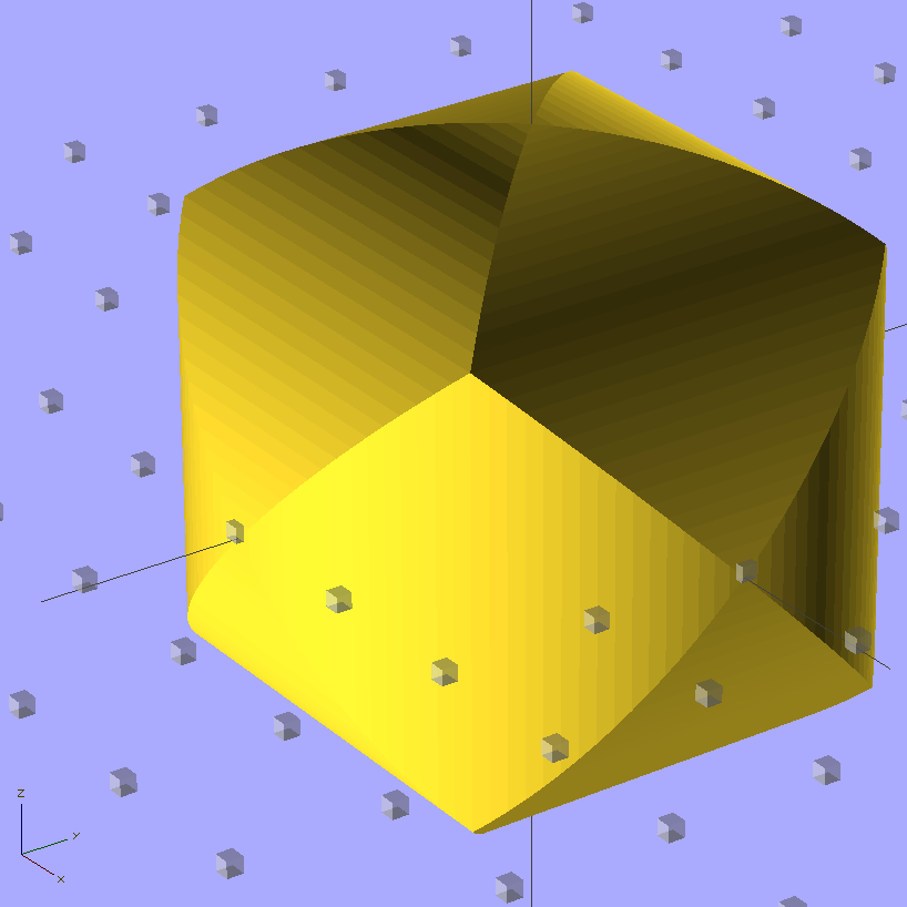
My buddy Mark One asked me to make a golf-ball sized Thing that’s the intersection of three mutually orthogonal cylinders. He claims I (subtractively) machined one from solid plastic, many many years ago, but I cannot imagine I ever had that level of machine shop fu; right now, I’m not sure how I’d fixture the thing.
Cylinder Thing – solid model
It’s much easier with a 3D printer…
Of course, spheroids aren’t printable without support, but you can chop one in half to reveal the nice, flat interior surfaces, then add holes for alignment pegs. Using 0.50 infill makes for a compact mesh inside the ball:
Cylinder Thing – building
Smooth a few imperfections from the mating surfaces and add four pegs (the other two are busy propping the right-hand half off the countertop). Somewhat to my surprise, the alignment holes came out a perfect push fit for the 2.9 mm actual-OD filament with my more-or-less standard 0.2 mm HoleWindageFinagle Constant. This also uses the 1.005 XY scale factor to adjust for ABS shrinkage, not that that matters in this case:
Cylinder Thing – alignment pegs
Then solvent-bond everything together forever more:
Cylinder Thing – clamped
The seam is almost imperceptible around the equator, perhaps because I didn’t slobber solvent right up to the edge. I did print one without the alignment pegs and demonstrated that you (well, I) can’t glue a spheroid without fixturing the halves; that one goes in my Show-n-Tell heap.
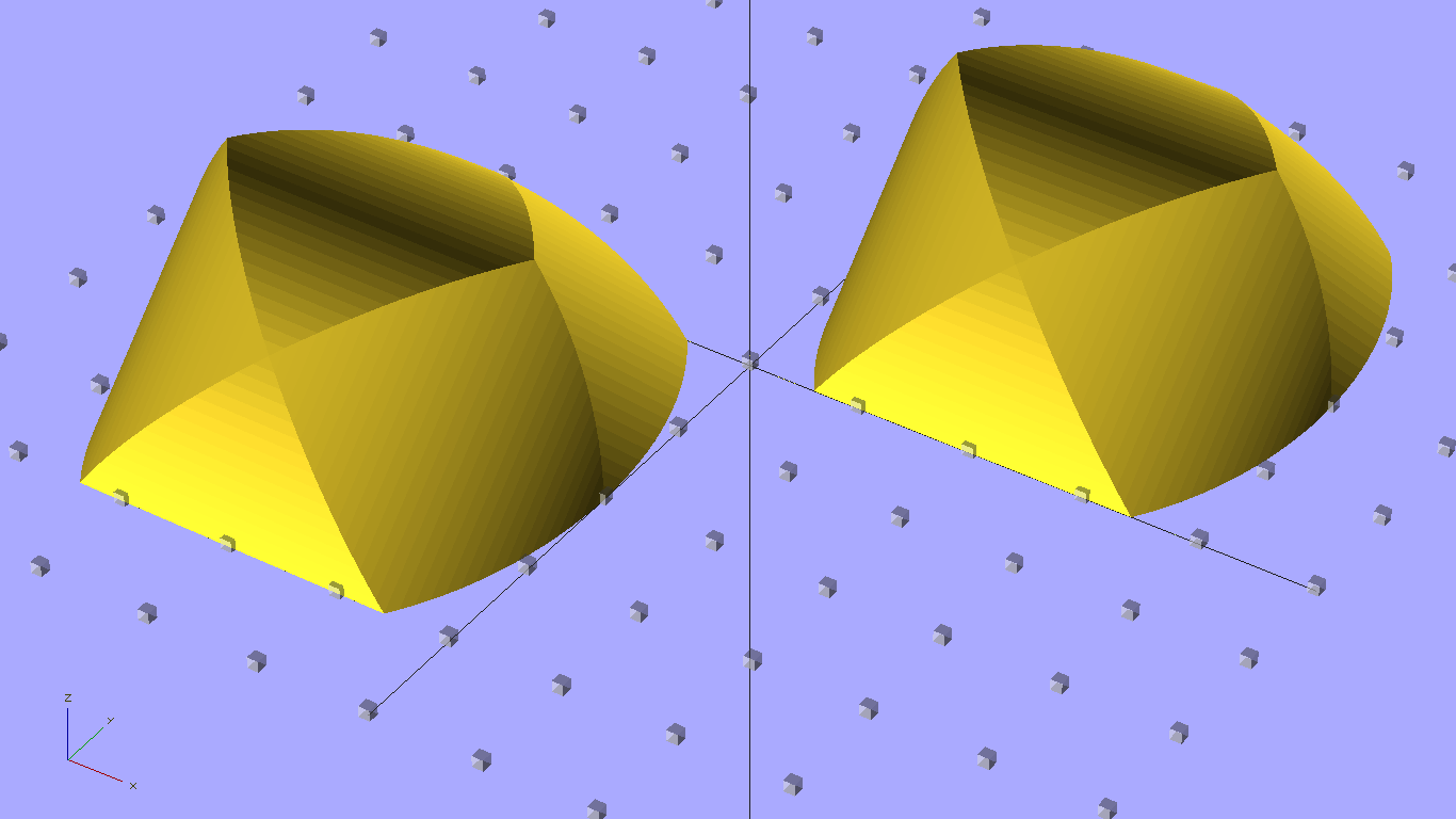
The 0.33 mm Z resolution produces sucky North and South poles; the East, West, Left, and Right poles are just fine, as are the eight Tropical Vertices. After mulling for a bit, I rotated a cylindrical profile upward:
Cylinder Thing Rotated – solid model
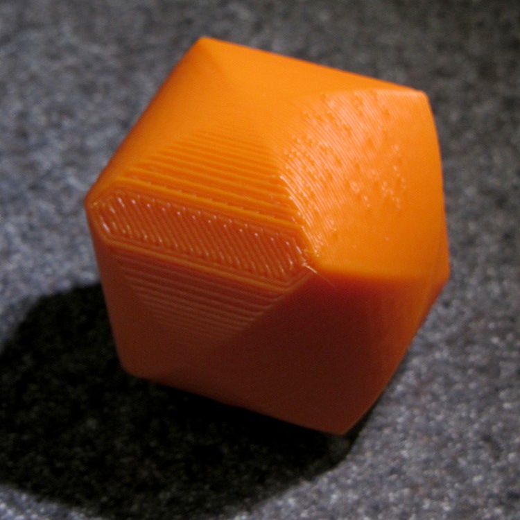
The obvious contour lines fit the cylinder much better, although you can see where better Z resolution would pay off:
Cylinder Thing – rotated
This was at 0.33 mm x 0.66 mm, 200 °C, 30 & 100 mm/s, 2 rpm. No delamination problems; I applied a wood chisel to persuade those big flat surfaces to part company with the Kapton tape.
The OpenSCAD source code:
// Three intersecting cylinders
// Ed Nisley KE4ZNU - Oct 2011

Layout = "Build";			// Show Build

//- Extrusion parameters must match reality!
//  Print with +1 shells and 3 solid layers
//  Use infill solidity = 0.5 or more...

ThreadThick = 0.33;
ThreadWidth = 2.0 * ThreadThick;

HoleWindage = 0.2;

Protrusion = 0.1;			// make holes end cleanly

//------ Model dimensions

CylDia = 2*IntegerMultiple(40.0/2,ThreadThick);
CylRad = CylDia/2;

echo(str("Actual diameter: ",CylDia));

Angle = [45,0,0];			// rotate to choose build orientation

$fn=128;

AlignPegDia = 2.90;

//-------

function IntegerMultiple(Size,Unit) = Unit * ceil(Size / Unit);

module PolyCyl(Dia,Height,ForceSides=0) {			// based on nophead's polyholes

  Sides = (ForceSides != 0) ? ForceSides : (ceil(Dia) + 2);

  FixDia = Dia / cos(180/Sides);

  cylinder(r=(FixDia + HoleWindage)/2,h=Height,$fn=Sides);
}

module ShowPegGrid(Space = 10.0,Size = 1.0) {

  Range = floor(50 / Space);

	for (x=[-Range:Range])
	  for (y=[-Range:Range])
		translate([x*Space,y*Space,Size/2])
		  %cube(Size,center=true);

}

//------- Model bits & pieces

module OneCyl() {
  cylinder(r=CylRad,h=CylDia,center=true);
}

module ThreeCyl() {
  intersection() {
	OneCyl();
	rotate([90,0,0]) OneCyl();
	rotate([0,90,0]) OneCyl();
  }
}

module HemiThing() {
  difference() {
	rotate(Angle)
	  ThreeCyl();
	translate([0,0,-CylRad])
		cube(CylDia,center=true);
	for (Index = [0:3])
	  rotate(Index*90)
		translate([CylRad/2,0,-Protrusion])
		  PolyCyl(AlignPegDia,5+Protrusion);
  }
}

//---------

ShowPegGrid();

if (Layout == "Show")
  ThreeCyl();

if (Layout == "Build") {
  translate([CylRad,CylRad,0])
	HemiThing();

  translate([-CylRad,-CylRad,0])
	  HemiThing();
}
The Wouxun KG-UV3D has three holes along the base that capture three tabs in the battery case, with tapered edges to align the case with the contacts. After a few passes to get the dimensions right, the plate matching those features came out like this:
Base plate with tabs
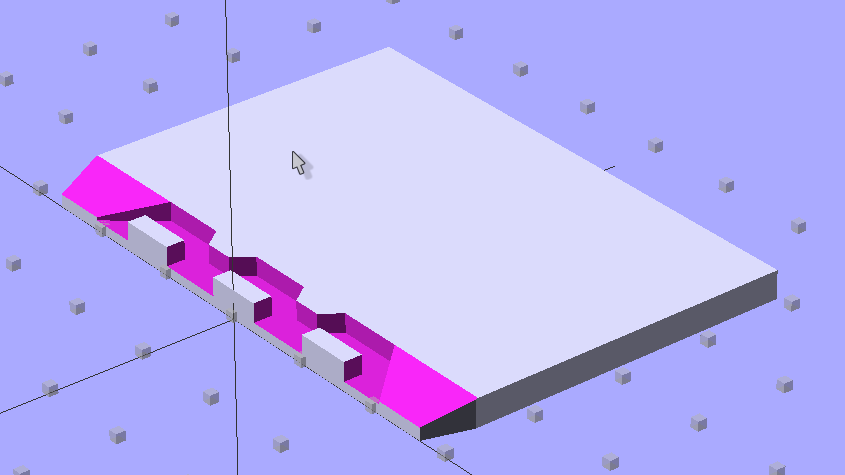
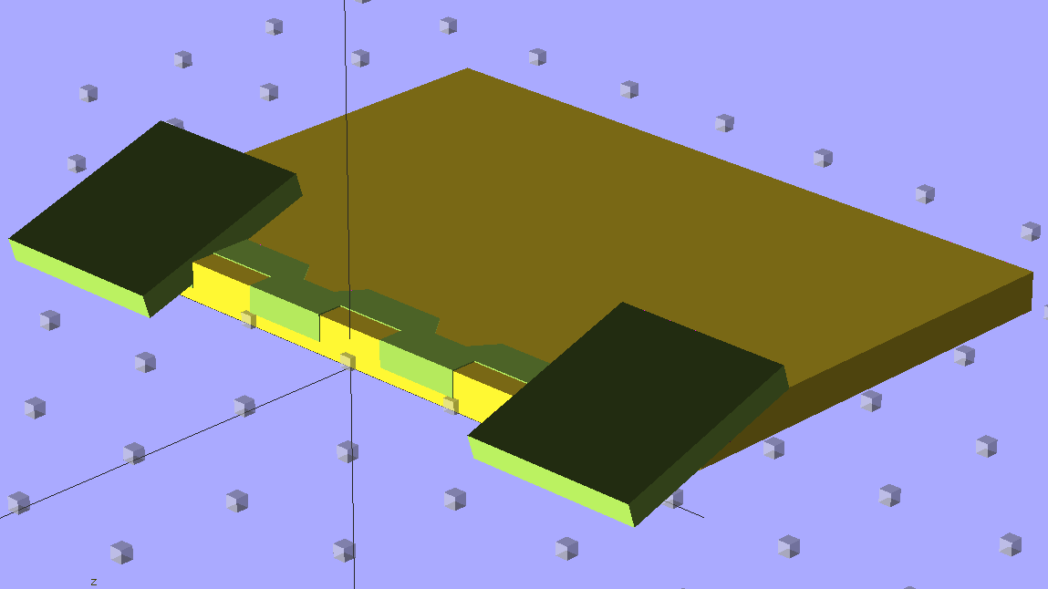
The solid model shows the edge tapering down to a single layer:
Case Tab Base – Solid Model
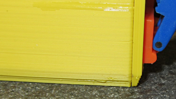
The compound taper on the corners must match both the base and the sides of the radio. The bottom plate and shell have corresponding tapers that extend across the glued joints:
Radio interface tapers
That worked out surprisingly well, given the small dimensions and odd angles. The tabs, in particular, bumped right up against the 0.66 mm extrusion width; they’re 2.0 mm thick, so there’s barely one thread width inside the perimeter for fill. A bit of filing & slicing removed the usual enlargement at the end / start of each perimeter thread on the tabs, which is entirely acceptable for something this finicky.
The OpenSCAD source code with dimensions is all part of that post, but here’s the radio base shape that gets subtracted from the plate to make those tabs:
Radio Base Polygon – solid model
This seemed easier than adding a bunch of tiny pegs & triangles, but it’s certainly tedious working around a polygon: