The Smell of Molten Projects in the Morning

Ed Nisley's Blog: Shop notes, electronics, firmware, machinery, 3D printing, laser cuttery, and curiosities. Contents: 100% human thinking, 0% AI slop.

Tag: Arduino

All things Arduino

  • Tour Easy 1 W Amber Running Light: Circuitry

    Tour Easy 1 W Amber Running Light: Circuitry

    With the internal slab attached to the 1 W LED heatsink, some double-sided foam tape affixes an Arduino Nano to one side of the slab:

    1 W LED Running Light - Arduino side
    1 W LED Running Light – Arduino side

    The MP1584 regulator and its 2.2 Ω current-sensing resistor (tacked down with acrylic adhesive) go on the other side:

    1 W LED Running Light - Regulator side
    1 W LED Running Light – Regulator side

    The Arduino and regulator draw power from the Bafang motor controller’s 6.3 V headlight circuit. The 2.2 Ω resistor sets the LED current to 360 mA = 900 mW. The blue wire connects the Arduino’s default LED output pin (D13) to the regulator’s Enable input (pin 2) to allow programmatic blinkiness.

    The end view shows everything Barely Fits™:

    1 W LED Running Light - internal assembly
    1 W LED Running Light – internal assembly

    All it needs is a rear cover of some sort …

  • Tour Easy 1 W Amber Running Light: Internal Plate

    Tour Easy 1 W Amber Running Light: Internal Plate

    A semi-scaled doodle laying out an Arduino Nano and the MP1584 regulator board suggested they might fit behind the heatsink with the 1 W LED:

    Amber running light - board layout doodle - side
    Amber running light – board layout doodle – side

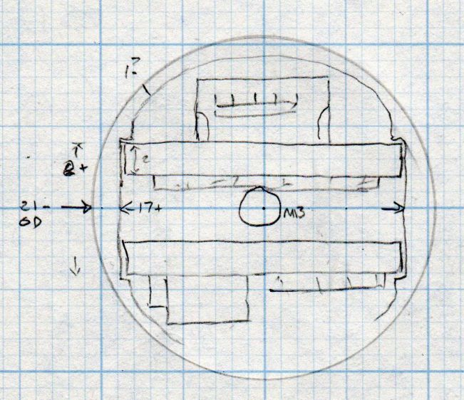
    A somewhat more detailed doodle of the end view prompted me to bore the PVC pipe out to 23 mm:

    Amber running light - board layout doodle - end
    Amber running light – board layout doodle – end

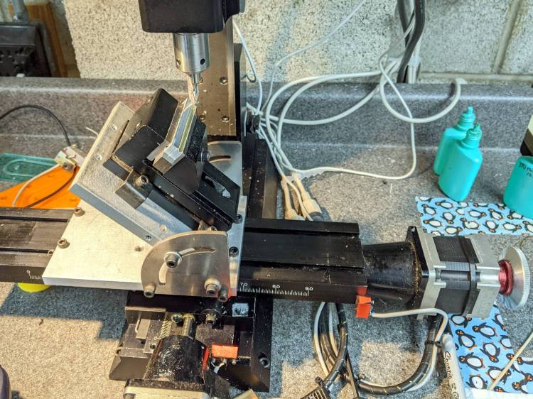
    The prospect of designing a 3D printed holder for the boards suggested Quality Shop Time combined with double-stick foam tape would ensure a better outcome.

    So I bandsawed the remains of a chunky angle bracket into a pair of rectangles, flycut All The Sides to square them up, and tapped a pair of M3 holes along one edge of each:

    1 W LED Running Light - baseplate tapping
    1 W LED Running Light – baseplate tapping

    The other long edges got the V groove that killed the Sherline’s Y axis nut:

    Sherline Y-Axis Nut Mishap - setup
    Sherline Y-Axis Nut Mishap – setup

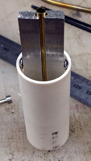
    The groove holds a length of 4 mm OD (actually 5/32 inch, but don’t tell anybody) brass tubing:

    1 W LED Running Light - baseplate trial fit
    1 W LED Running Light – baseplate trial fit

    The M3 button head screws are an admission of defeat, as I could see no way of controlling the width + thickness of the aluminum slabs to get a firm push fit in the PVC tube. The screws let me tune for best picture after everything else settled out.

    A little more machining opened up the top of the groove:

    1 W LED Running Light - baseplate dry assembly
    1 W LED Running Light – baseplate dry assembly

    A short M3 button head screw (with its head turned down to 4 mm) drops into the slot and holds the slab to the threaded hole in the LED heatsink. The long screw is holding the threaded insert in place for this dry fit.

    I doodled a single long screw through the whole thing, but having it fall off the heatsink when taking the rear cover off seemed like a Bad Idea™. An M3 button head screw uses a 2 mm hex key that fits neatly through the threaded insert, thereby making it work.

    Butter it up with epoxy, scrape off the excess, and let things cure:

    1 W LED Running Light - baseplate curing
    1 W LED Running Light – baseplate curing

    This was obviously made up as I went along …

  • Arduino MEGA Debugging LEDs

    Arduino MEGA Debugging LEDs

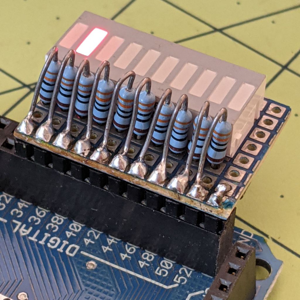
    Kibitzing on a project involving an Arduino Mega (properly MEGA, but who cares?) with plenty of spare I/O pins led me to slap together a block of LEDs:

    Arduino Mega Debugging LEDs
    Arduino Mega Debugging LEDs

    The excessive lead length on the 330 Ω resistors will eventually anchor scope probes syncing on / timing interesting program events.

    Not that you have any, but they’re antique HP HDSP-4836 tuning indicators: RRYYGGYYRR. If you were being fussy, you might use 270 Ω resistors on the yellow LEDs to brighten them up.

    A simple test program exercises the LEDs:

    /*
      Debugging LED outputs for Mega board
      Ed Nisley - KE4ZNU
      Plug the board into the Digital Header pins 34-52 and GND 
    */
    
    byte LowLED = 34;
    byte HighLED = 52;
    byte ThisLED = LowLED;
    
    //-----
    void setup() {
      pinMode(LED_BUILTIN,OUTPUT);
      
      for (byte p = LowLED; p <= HighLED; p+=2)
        pinMode(p, OUTPUT);
    
    //  Serial.begin(9600);
    }
    
    // -----
    void loop() {
      digitalWrite(LED_BUILTIN,HIGH);
      
      digitalWrite(ThisLED, HIGH);
      delay(100);
      digitalWrite(ThisLED, LOW);
     // delay(500);
    
      ThisLED = (ThisLED < HighLED) ? (ThisLED + 2) : LowLED;
    
    //  Serial.println(ThisLED);
    
      digitalWrite(LED_BUILTIN,LOW);
    }


    Nothing fancy, but it ought to come in handy at some point.

  • KeyboardIO Atreus: RGB LED Firmware

    KeyboardIO Atreus: RGB LED Firmware

    Having wired a WS2812 RGB LED into my KeyboardIO Atreus, lighting it up requires some QMK firmware configuration. It’s easiest to set up a “new” keymap based on the QMK Atreus files, as described in the QMK startup doc:

    qmk new-keymap -kb keyboardio/atreus -km ednisley

    Obviously, you’ll pick a different keymap name than I did. All the files mentioned below will reside in the new subdirectory, which starts out with only a keymap.c file copied from the default layout.

    The rules.mk file enables RGB Lighting, as well as Auto Shift and Tap Dance:

    AUTO_SHIFT_ENABLE = yes			# allow automagic shifting
    TAP_DANCE_ENABLE = yes			# allow multi-tap keys
    
    RGBLIGHT_ENABLE = yes			# addressable LEDs
    

    If you had different hardware, you could specify the driver with a WS2812_DRIVER option.

    QMK can also control single-color LEDs with PWM (a.k.a. backlighting), and per-key RGB LEDs (a.k.a. RGB Matrix). These functions, their configuration / controls / data, and their documentation overlap and intermingle to the extent that I spent most of my time figuring out what not to include.

    Some configuration happens in the config.h file:

    #define RGB_DI_PIN B2
    #define RGBLED_NUM 1
    
    // https://github.com/qmk/qmk_firmware/blob/master/docs/ws2812_driver.md
    //#define WS2812_TRST_US 280
    //#define WS2812_BYTE_ORDER WS2812_BYTE_ORDER_GRB
    
    #define RGBLIGHT_LAYERS
    #define RGBLIGHT_EFFECT_RGB_TEST
    #define RGBLIGHT_LIMIT_VAL 63
    
    #define NO_DEBUG
    #define NO_PRINT
    

    The first two lines describe a single WS2812 RGB LED wired to pin B2 (a.k.a. MOSI) of the Atmel 32U4 microcontroller. The default Reset duration and Byte Order values work for the LED I used

    Protip: swapping the order from GRB to RGB is a quick way to discover if the firmware actually writes to the LED, even before you get anything else working: it’ll be red with the proper setting and green with the wrong one.

    Dialing the maximum intensity down works well with a bright LED shining directly at your face from a foot away.

    Turning on RGBLIGHT_LAYERS is what makes this whole thing happen. The RGBLIGHT_EFFECT_RGB_TEST option enables a simple test animation at the cost of a few hundred bytes of code space; remove that line after everything works.

    The last two lines remove the debugging facilities; as always with microcontroller projects, there’s enough room for either your code or the debugger required to get it running, but not both.

    With those files set up, the keymap.c file does the heavy lifting:

    // Modified from the KeyboardIO layout
    // Ed Nisley - KE4ZNU
    
    #include QMK_KEYBOARD_H
    
    enum layer_names {
        _BASE,
        _SHIFTS,
        _FUNCS,
        _NLAYERS
    };
    
    // Tap Dance
    
    enum {
        TD_SPC_ENT,
    };
    
    qk_tap_dance_action_t tap_dance_actions[] = {
        [TD_SPC_ENT] = ACTION_TAP_DANCE_DOUBLE(KC_SPC, KC_ENT),
    };
    
    
    // Layer lighting
    
    // Undefine this to enable simple test mode
    // Also put #define RGBLIGHT_EFFECT_RGB_TEST in config.h
    
    #define LED_LL
    
    #ifdef LED_LL
    
    const rgblight_segment_t PROGMEM ll_0[] = RGBLIGHT_LAYER_SEGMENTS( {0,1,HSV_WHITE} );
    const rgblight_segment_t PROGMEM ll_1[] = RGBLIGHT_LAYER_SEGMENTS( {0,1,HSV_MAGENTA} );
    const rgblight_segment_t PROGMEM ll_2[] = RGBLIGHT_LAYER_SEGMENTS( {0,1,HSV_CYAN} );
    const rgblight_segment_t PROGMEM ll_3[] = RGBLIGHT_LAYER_SEGMENTS( {0,1,HSV_BLUE} );
    const rgblight_segment_t PROGMEM ll_4[] = RGBLIGHT_LAYER_SEGMENTS( {0,1,HSV_GREEN} );
    const rgblight_segment_t PROGMEM ll_5[] = RGBLIGHT_LAYER_SEGMENTS( {0,1,HSV_RED} );
    const rgblight_segment_t PROGMEM ll_6[] = RGBLIGHT_LAYER_SEGMENTS( {0,1,HSV_YELLOW} );
    
    const rgblight_segment_t* const PROGMEM ll_layers[] = RGBLIGHT_LAYERS_LIST(
        ll_0,ll_1,ll_2,ll_3,ll_4,ll_5,ll_6
    );
    
    #endif
    
    void keyboard_post_init_user(void) {
    
    #ifdef LED_LL
        rgblight_layers = ll_layers;
        rgblight_set_layer_state(0, 1);
    #else
        rgblight_enable_noeeprom();
        rgblight_mode_noeeprom(RGBLIGHT_MODE_RGB_TEST);
    //    rgblight_mode_noeeprom(RGBLIGHT_MODE_BREATHING + 3);
    #endif
    
    }
    
    
    #ifdef LED_LL
    
    layer_state_t layer_state_set_user(layer_state_t state) {
        for (uint8_t i=0 ; i < _NLAYERS; i++)
            rgblight_set_layer_state(i, layer_state_cmp(state, i));
    
        return state;
    }
    #endif
    
    
    // Key maps
    
    const uint16_t PROGMEM keymaps[][MATRIX_ROWS][MATRIX_COLS] = {
      [_BASE] = LAYOUT(                             // base layer for typing
        KC_Q,    KC_W,    KC_E,    KC_R,    KC_T,                      KC_Y,    KC_U,    KC_I,    KC_O,    KC_P    ,
        KC_A,    KC_S,    KC_D,    KC_F,    KC_G,                      KC_H,    KC_J,    KC_K,    KC_L,    KC_SCLN ,
        KC_Z,    KC_X,    KC_C,    KC_V,    KC_B,    KC_GRV,  KC_LALT, KC_N,    KC_M,    KC_COMM, KC_DOT,  KC_SLSH ,
        LT(_FUNCS,KC_ESC), KC_TAB, KC_LGUI,  KC_BSPC, KC_LSFT,  KC_LCTL, KC_ENT , TD(TD_SPC_ENT),  MO(_SHIFTS), KC_MINS, KC_QUOT, KC_BSLS),
    
      [_SHIFTS] = LAYOUT(                           // shifted chars and numpad
        KC_EXLM, KC_AT,   KC_UP,   KC_DLR,  KC_PERC,                  KC_PGUP, KC_7,    KC_8,   KC_9, KC_HOME,
        KC_LPRN, KC_LEFT, KC_DOWN, KC_RGHT, KC_RPRN,                  KC_PGDN, KC_4,    KC_5,   KC_6, KC_END,
        KC_LBRC, KC_RBRC, KC_HASH, KC_LCBR, KC_RCBR, KC_CIRC, KC_AMPR,KC_ASTR, KC_1,    KC_2,   KC_3, KC_PLUS,
        KC_NO  , KC_INS,  KC_LGUI, KC_DEL , KC_BSPC, KC_LCTL, KC_LALT,KC_SPC,  KC_TRNS, KC_DOT, KC_0, KC_EQL ),
    
      [_FUNCS] = LAYOUT(                            // function keys
        KC_INS,  KC_HOME, KC_UP,   KC_END,  KC_PGUP,                   KC_UP,   KC_F7,   KC_F8,   KC_F9,   KC_F10  ,
        KC_DEL,  KC_LEFT, KC_DOWN, KC_RGHT, KC_PGDN,                   KC_DOWN, KC_F4,   KC_F5,   KC_F6,   KC_F11  ,
        KC_NO,   KC_VOLU, KC_NO,   KC_NO,   RESET,   _______, _______, KC_NO,   KC_F1,   KC_F2,   KC_F3,   KC_F12  ,
        KC_NO,   KC_VOLD, KC_LGUI, KC_LSFT, KC_BSPC, KC_LCTL, KC_LALT, KC_SPC,  TO(_BASE), KC_PSCR, KC_SLCK, KC_PAUS )
    };
    

    Undefine LED_LL to enable the test mode, compile, flash, and the LED should cycle red / green / blue forever; you also need the RGB_TEST option in the config.h file.

    Define LED_LL and layer lighting should then Just Work™, with the LED glowing:

    • White for the basic layer with all the letters
    • Magenta with the Fun key pressed
    • Cyan with the Esc key pressed

    The key map code defines colors for layers that don’t yet exist, but it should get you started.

    For convenience, I wadded all three QMK files into a GitHub Gist.

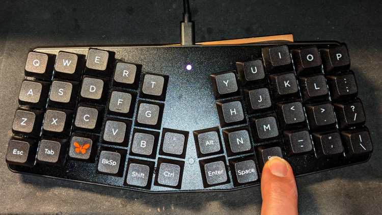
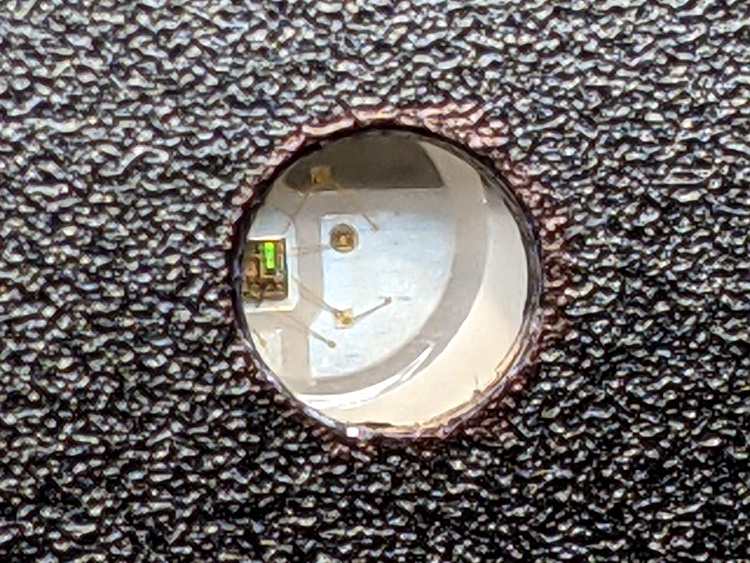
    The LED is kinda subtle:

    Atreus keyboard - LED installed
    Atreus keyboard – LED installed

    As you might expect, figuring all that out took much longer than for you to read about it, but now I have a chance of remembering what I did.

  • KeyboardIO Atreus: RGB LED Installation

    KeyboardIO Atreus: RGB LED Installation

    Having scouted out the territory inside the KeyboardIO Atreus, adding an LED requires taking it completely apart to drill a hole in the aluminum faceplate:

    Atreus keyboard - panel drilling
    Atreus keyboard – panel drilling

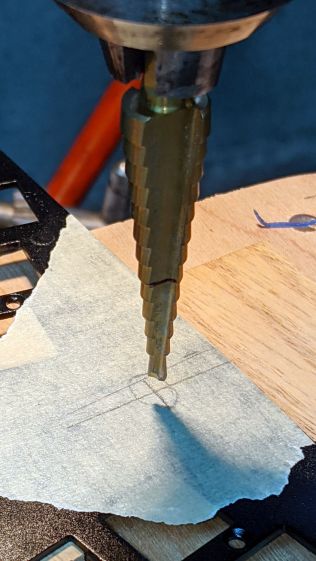
    Reattaching the plate to the PCB with only three screws allows marking the hole position on the PCB, which is much easier than pretending to derive the position from first principles:

    Atreus keyboard - LED marking
    Atreus keyboard – LED marking

    Despite appearances, I traced the hole with a mechanical pencil: black graphite turns shiny silvery gray against matte black soldermask. Also, the PCB trace is off-center, not the hole.

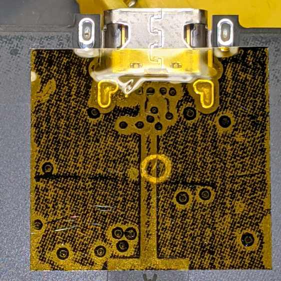
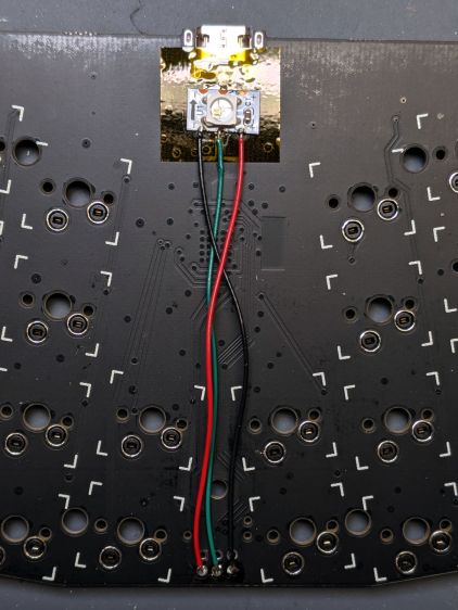
    Overlay the neighborhood with Kapton tape to protect the PCB from what comes next:

    Atreus keyboard - Kapton tape

    Snip a WS2812 RGB LED from a strip, stick it in place with eyeballometric alignment over the target, and wire it up:

    Atreus keyboard - LED wiring
    Atreus keyboard – LED wiring

    Despite the terrible reliability of WS2812 RGB LEDs mounted on PCB carriers, a different set on a meter of high-density flex tape have worked reasonably well when not thermally stressed, so I’ll assume this one arrived in good order.

    Aligning the LED directly under the hole required a few iterations:

    Atreus keyboard - LED positioning
    Atreus keyboard – LED positioning

    The iridescent green patch is a diffraction pattern from the controller chip’s internal circuitry.

    The data comes from MOSI, otherwise known as B2, down in the lower left corner:

    Atmel 32U4 - JTAG pins
    Atmel 32U4 – JTAG pins

    Actually lighting the LED now becomes a simple matter of software QMK firmware.

  • Atreus Keyboard: LED Thoughts

    Atreus Keyboard: LED Thoughts

    Having helped grossly over-fund the Atreus Kickstarter earlier this year, a small box arrived pretty much on-time:

    Atreus keyboard - overview
    Atreus keyboard – overview

    I did get the blank keycap set, but have yet to screw up sufficient courage to install them. The caps sit atop the stock Kailh (pronounced, I think, kale) BOX Brown soft tactile switches; they’re clicky, yet not offensively loud.

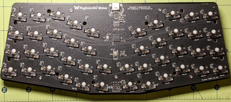
    Removing a dozen screws lets you take it apart, revealing all the electronics on the underside of the PCB:

    Atreus keyboard - PCB overview
    Atreus keyboard – PCB overview

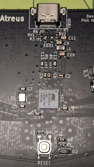
    The central section holds most of the active ingredients:

    Atreus keyboard - USB 32U4 Reset - detail
    Atreus keyboard – USB 32U4 Reset – detail

    The Atmel MEGA32U4 microcontroller runs a slightly customized version of QMK:

    Atreus keyboard - 32U4 - detail
    Atreus keyboard – 32U4 – detail

    Of interest is the JTAG header at the front center of the PCB:

    Atreus keyboard - JTAG header
    Atreus keyboard – JTAG header

    I have yet to delve into the code, but I think those signals aren’t involved with the key matrix and one might be available to drive an addressable RGB LED.

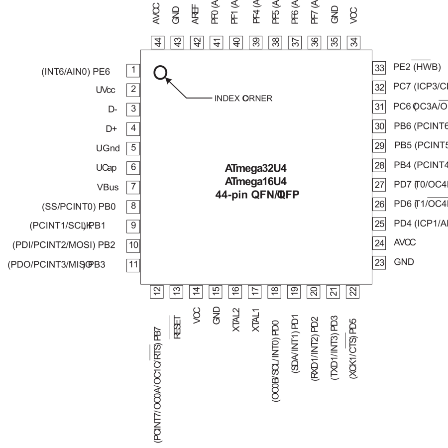
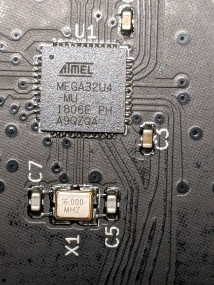
    For future reference, they’re tucked into the lower left corner of the chip (the mauled format comes from the original PDF):

    Atmel 32U4 - JTAG pins
    Atmel 32U4 – JTAG pins

    The alternate functions:

    • SCK = PB1
    • MOSI = PB2
    • MISO = PB3

    I don’t need exotic lighting, but indicating which key layer is active would be helpful.

    Love the key feel, even though I still haven’t hit the B key more than 25% of the time.

  • Raspberry Pi Interrupts vs. Rotary Encoder

    Raspberry Pi Interrupts vs. Rotary Encoder

    Thinking about using a rotary encoder to focus a Raspberry Pi lens led to a testbed:

    RPi knob encoder test setup
    RPi knob encoder test setup

    There’s not much to it, because the RPi can enable pullup resistors on its digital inputs, whereupon the encoder switches its code bits to common. The third oscilloscope probe to the rear syncs on a trigger output from my knob driver.

    I started with the Encoder library from PyPi, but the setup code doesn’t enable the pullup resistors and the interrupt (well, it’s a callback) handler discards the previous encoder state before using it, so the thing can’t work. I kept the overall structure, gutted the code, and rebuilt it around a state table. The code appears at the bottom, but you won’t need it.

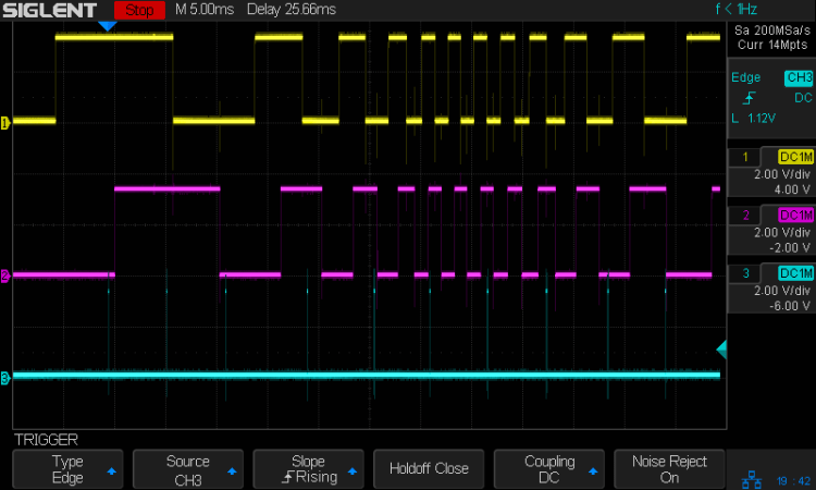
    Here’s the problem, all in one image:

    Knob Encoder - ABT - fast - overview
    Knob Encoder – ABT – fast – overview

    The top two traces are the A and B encoder bits. The bottom trace is the trigger output from the interrupt handler, which goes high at the start of the handler and low at the end, with a negative blip in the middle when it detects a “no motion” situation: the encoder output hasn’t changed from the last time it was invoked.

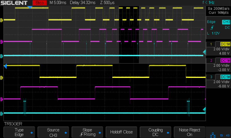
    Over on the left, where the knob is turning relatively slowly, the first two edges have an interrupt apiece. A detailed view shows them in action (the bottom half enlarge the non-shaded part of the top half):

    Knob Encoder - ABT - fast - first IRQs
    Knob Encoder – ABT – fast – first IRQs

    Notice that each interrupt occurs about 5 ms after the edge causing it!

    When the edges occur less than 5 ms apart, the driver can’t keep up. The next four edges produce only three interrupts:

    Knob Encoder - ABT - fast - 4 edges 3 IRQ
    Knob Encoder – ABT – fast – 4 edges 3 IRQ

    A closer look at the three interrupts shows all of them produced the “no motion” pulse, because they all sampled the same (incorrect) input bits:

    Knob Encoder - ABT - fast - 4 edges 3 IRQ - detail
    Knob Encoder – ABT – fast – 4 edges 3 IRQ – detail

    In fact, no matter how many edges occur, you only get three interrupts:

    Knob Encoder - ABT - fast - 9 edges 3 IRQ
    Knob Encoder – ABT – fast – 9 edges 3 IRQ

    The groups of interrupts never occur less than 5 ms apart, no matter how many edges they’ve missed. Casual searching suggests the Linux Completely Fair Scheduler has a minimum timeslice / thread runtime around 5 ms, so the encoder may be running at the fastest possible response for a non-real-time Raspberry Pi kernel, at least with a Python handler.

    If. I. Turn. The. Knob. Slowly. Then. It. Works. Fine. But. That. Is. Not. Practical. For. My. Purposes.

    Nor anybody else’s purposes, really, which leads me to think very few people have ever tried lashing a rotary encoder to a Raspberry Pi.

    So, OK, I’ll go with Nearer and Farther focusing buttons.

    The same casual searching suggested tweaking the Python thread’s priority / niceness could lock it to a different CPU core and, obviously, writing the knob handler in C / C++ / any other language would improve the situation, but IMO the result doesn’t justify the effort.

    It’s worth noting that writing “portable code” involves more than just getting it to run on a different system with different hardware. Rotary encoder handlers are trivial on an Arduino or, as in this case, even an ARM-based Teensy, but “the same logic” doesn’t deliver the same results on an RPi.

    My attempt at a Python encoder driver + simple test program as a GitHub Gist:

    # Rotary encoder test driver
    # Ed Nisley – KE4ZNU
    # Adapted from https://github.com/mivallion/Encoder
    # State table from https://github.com/PaulStoffregen/Encoder
    import RPi.GPIO as GPIO
    class Encoder(object):
    def __init__(self, A, B, T=None, Delay=None):
    GPIO.setmode(GPIO.BCM)
    self.T = T
    if T is not None:
    GPIO.setup(T, GPIO.OUT)
    GPIO.output(T,0)
    GPIO.setup(A, GPIO.IN, pull_up_down=GPIO.PUD_UP)
    GPIO.setup(B, GPIO.IN, pull_up_down=GPIO.PUD_UP)
    self.delay = Delay
    self.A = A
    self.B = B
    self.pos = 0
    self.state = (GPIO.input(B) << 1) | GPIO.input(A)
    self.edges = (0,1,-1,2,-1,0,-2,1,1,-2,0,-1,2,-1,1,0)
    if self.delay is not None:
    GPIO.add_event_detect(A, GPIO.BOTH, callback=self.__update,
    bouncetime=self.delay)
    GPIO.add_event_detect(B, GPIO.BOTH, callback=self.__update,
    bouncetime=self.delay)
    else:
    GPIO.add_event_detect(A, GPIO.BOTH, callback=self.__update)
    GPIO.add_event_detect(B, GPIO.BOTH, callback=self.__update)
    def __update(self, channel):
    if self.T is not None:
    GPIO.output(self.T,1) # flag entry
    state = (self.state & 0b0011) \
    | (GPIO.input(self.B) << 3) \
    | (GPIO.input(self.A) << 2)
    gflag = '' if self.edges[state] else ' – glitch'
    if (self.T is not None) and not self.edges[state]: # flag no-motion glitch
    GPIO.output(self.T,0)
    GPIO.output(self.T,1)
    self.pos += self.edges[state]
    self.state = state >> 2
    # print(' {} – state: {:04b} pos: {}{}'.format(channel,state,self.pos,gflag))
    if self.T is not None:
    GPIO.output(self.T,0) # flag exit
    def read(self):
    return self.pos
    def read_reset(self):
    rv = self.pos
    self.pos = 0
    return rv
    def write(self,pos):
    self.pos = pos
    if __name__ == "__main__":
    import encoder
    import time
    from gpiozero import Button
    btn = Button(26)
    enc = encoder.Encoder(20, 21,T=16)
    prev = enc.read()
    while not btn.is_held :
    now = enc.read()
    if now != prev:
    print('{:+4d}'.format(now))
    prev = now
    view raw encoder.py hosted with ❤ by GitHub