Ed Nisley's Blog: Shop notes, electronics, firmware, machinery, 3D printing, laser cuttery, and curiosities. Contents: 100% human thinking, 0% AI slop.
Category: Software
General-purpose computers doing something specific
Run the program ten times to generate ten SVG images:
for i in {00..09} ; do python Layers\ -\ 24x18.py --layernum=$i --colors=9 > Test_$i.svg ; done
The LightBurn layout dwarfs the machine platform:
Layered Paper – circular colors – 24x18in – LightBurn layout
Fire The Laser ten times and you get a wall hanging:
Layered Paper – 24×18 – trial alignment
That’s a trial alignment atop a cardboard box on the Basement Shop floor, because gluing those 24×18 inch sheets of paper requires time on the Sewing Table, which is currently occupied by a much higher priority project. The brown innermost circle in the design is entirely separate from the brown Amazon cardboard box underneath everything.
Fairly obviously, you’d want something other than brown at the focal point of that design, but following the EIA color code gives me some confidence the result matches the intention. Feel free to tart it up with your own colors.
I laid a 29×23 inch sheet of sketch paper on the honeycomb, distributed neodymium bar magnets around the perimeter, and cut a 24×18 rectangle out of the middle:
Layered Paper – 24×18 – brown squares
Those squares are the cutouts from the brown sheet, minus what you see in the lead picture.
The black rectangle on the left of the LightBurn layout above is the 24×18 inch cut for the fixture. Centering that rectangle on the LightBurn layout (click-select, Ctrl-D to duplicate, then hit P to move it to the center) means aligning each of the ten patterns requires nothing more than the same click-select / dupe / P, with no delicate fiddling.
Then just lay each colored sheet into the hole and it’s properly aligned. Because the machine homes to the same physical location every time it’s turned on and the fixture is mmm fixed to the platform, cutting all ten sheets over the course of two days proceeded smoothly.
Cutting 2537 holes in the black mask takes a little under an hour:
Layered Paper – 24×18 – cutting black
The other sheets have fewer holes and go progressively faster:
Layered Paper – 24×18 – cutting yellow
The white sheet on the bottom has four alignment holes and four layer ID holes, so the cuts take a few seconds.
Thresholding the distance from a randomly chosen point creates circular rainbows:
CenterPoint = (choice(range(args.width)),choice(range(args.height)))

CellMatrix = [[math.hypot(x - CenterPoint[X],y - CenterPoint[Y])
                for y in range(args.height)]
                for x in range(args.width)]

dmax = max(list(chain.from_iterable(CellMatrix)))

LayerThreshold = (ThisLayer/Layers)*dmax
The Python program generates one SVG image file representing a single layer, as determined by the Bash one-liner invoking it:
for i in {00..16} ; do python Layers\ -\ 200mm.py > Test_$i.svg ; done
In real life you’d also use a different random seed for each set of layers, but that’s just another command line optIon.
Import those 17 SVG images into LightBurn, arrange neatly, snap each one to the middle of the workspace grid (and thus the aligned template), then Fire The Laser:
Feeding paper into the laser in rainbow (actually, heavily augmented / infilled EIA color code) order, plus the black mask, produces the aforementioned pleasing result:
Layered Paper – rainbow oblique view
Glue the sheets in the assembly fixture:
Layered Paper – gluing fixture side view
The white layer is uncut, other than the four alignment holes (with a rivnut poking up) and its binary layer number (16, backwards because upside-down), and appears in only the farthest corners of the rainbow.
Protip: doing the stack upside-down means you smear glue stick on the hidden side of each sheet. If you avoid slobbering glue into the cut square holes, nothing can go wrong.
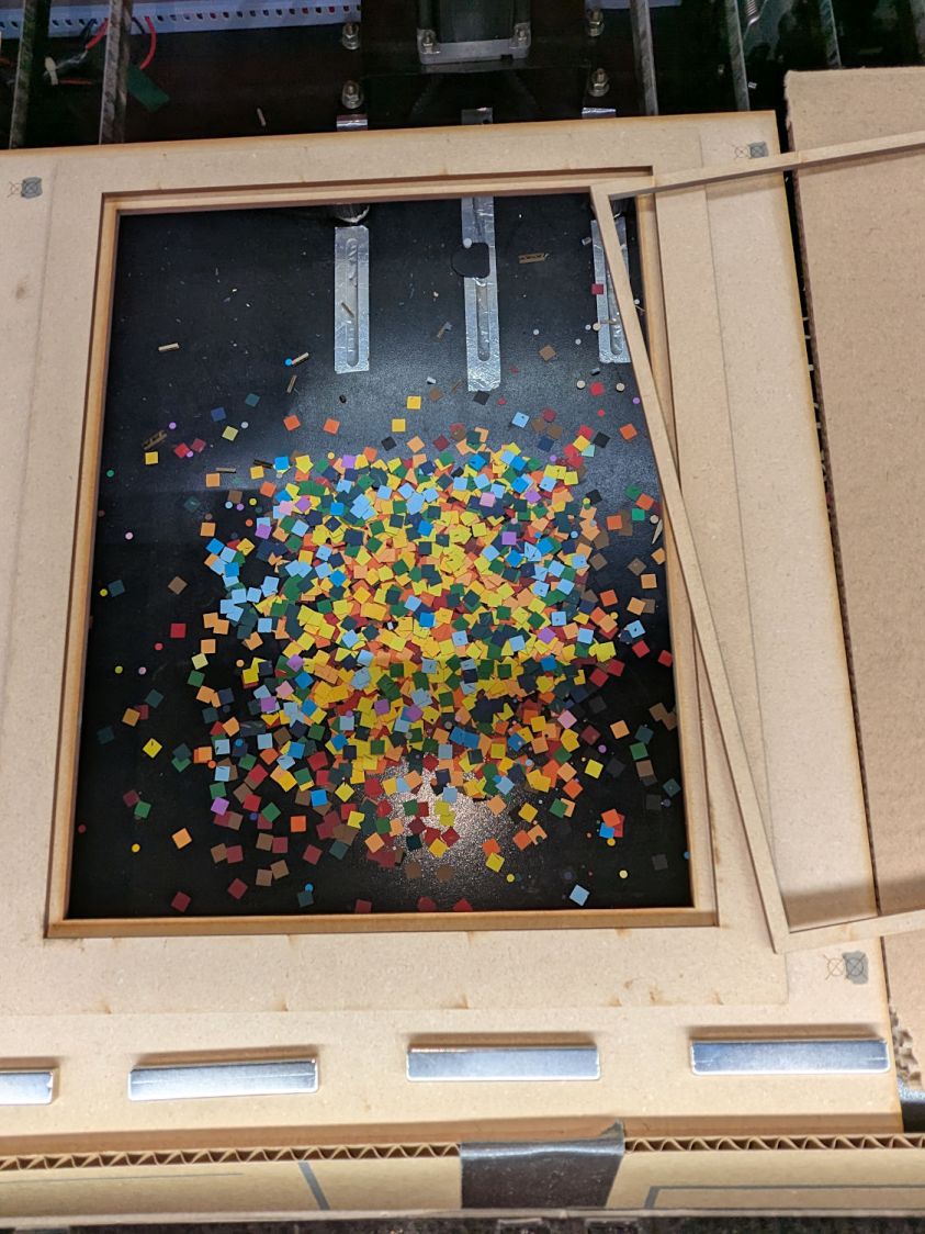
Making these things produces the happiest chip tray ever:
Layered Paper – rainbow chip tray
I swept half a dozen pictures worth of squares into a small box and gave it away to someone with a larger small-child cross-section than mine, whereupon a slight finger fumble turned the contents into a glitter bomb. Sorry ’bout that.
This file contains hidden or bidirectional Unicode text that may be interpreted or compiled differently than what appears below. To review, open the file in an editor that reveals hidden Unicode characters.
Learn more about bidirectional Unicode characters
# cut layer ID holes except on mask layer
if ThisLayer > 0:
    c = ((1,1))
    h = f'{ThisLayer:0{Layers.bit_length()}b}'
    for i in range(Layers.bit_length()):
        SheetEls.append(
            svg.Circle(
                cx=as_mm(SheetCenter[X] + c[X]*AlignOC[X]/2 - (i + 2)*AlignOD),
                cy=as_mm(SheetCenter[Y] + c[Y]*AlignOC[Y]/2),
                r=AlignOD/4 if h[-(i + 1)] == '1' else AlignOD/8,
                stroke=SheetCut,
                stroke_width=DefStroke,
                fill="none",
             )
        )
Filling the matrix of blocks with random numbers turned out to be a one-liner:
CellMatrix = [[randint(1,args.colors) for _ in range(args.height)] for _ in range(args.width)]
That matrix is a constant for all the layers, which is why you must feed the program the same random number seed to generate the layers.
Given the layer number and that matrix, deciding what to do for each hole is a walk through the cells:
MatrixEls = []                  # accumulates matrix cuts
for i in range(args.width):
    x =i*CellOC[X]
    for j in range(args.height):
        y = j*CellOC[Y]

        if ThisLayer == 0:                          # black mask
            s = HeavyCellCut
        elif ThisLayer < CellMatrix[i][j]:          # rest of sheets above color layer
            s = CellCut
        else:
            s = Tooling                             # at or below color layer

        MatrixEls.append(
            svg.Rect(
                x=as_mm(SheetCenter[X] - MatrixOA[X]/2 + x),
                y=as_mm(SheetCenter[Y] - MatrixOA[Y]/2 + y),
                width=as_mm(CellSize[X]),
                height=as_mm(CellSize[Y]),
                stroke=s,
                stroke_width=DefStroke,
                fill="none",
            )
        )
After accumulating all the other elements in similar lists, this creates and emits the entire SVG file to stdout:
The whole program has a bit more going on, but those are the high points.
Invoke the program with a Bash one-liner:
for i in {00..08} ; do python Layers.py --layernum=$i > Test_$i.svg ; done
That produces nine SVG image files that you import into LightBurn and arrange in a tidy array:
Layered Paper – Random Blocks – MVP – LightBurn import
I discovered that holding down the Shift key while importing the SVG files stacks them at the workspace origin (the upper-right corner for my machine) in the order of the file names, so clicking on the stack selects successive layers in the right order; just drop each one wherever you need it, then tidy the lineup.
The Python program sets the vector stroke colors using LightBurn palette values, so that LightBurn automagically assigns them to the appropriate layers. It turns out the black paper I used for the mask requires different speed / power values than the other colored paper.
I put the alignment features on a different layer than the matrix holes to make them more visible, even though they have the same speed / power values.
Align the template so the middle of the layer pattern is in the middle of the grid, then use LightBurn’s Print and Cut to align the template with the fixture on the laser platform:
Layered Paper – Random Blocks – MVP – template
Then the process requires just a few clicks per layer:
Drop a sheet of paper into the fixture
Click to select a layer layout
Ctrl-D to duplicate it
P to snap it to the middle of the grid
Alt-S to Fire The Laser
Del to delete that layer (which is why it’s a duplicate!)
Iterate until done!
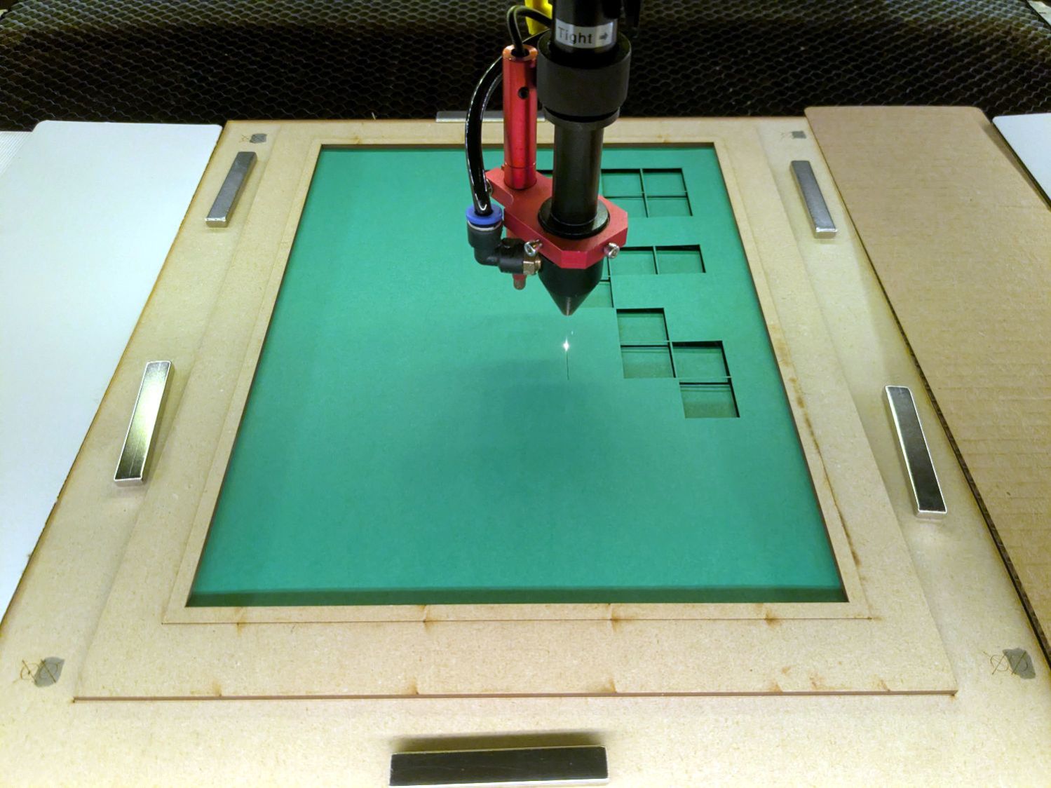
Which looks pretty much like you’d expect:
Layered Paper – Random Blocks – cutting
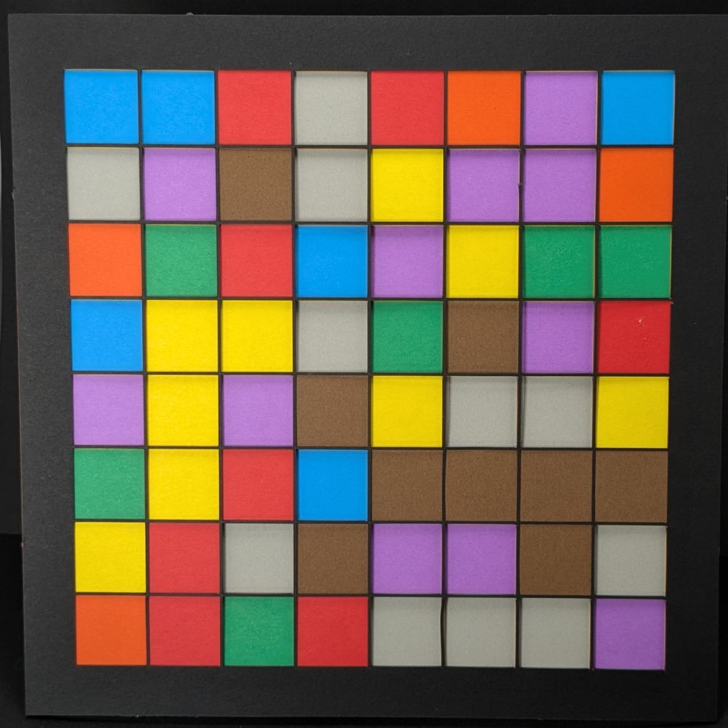
Take the stack of paper to the workbench, use an Xacto knife to cut the tabs holding the square into the Letter page, apply glue stick, stack in the fixture, and iterate to create a solid sheet with lots of holes:
Layered Paper – Random Blocks – MVP
More refinement is in order, but that’s the overview …
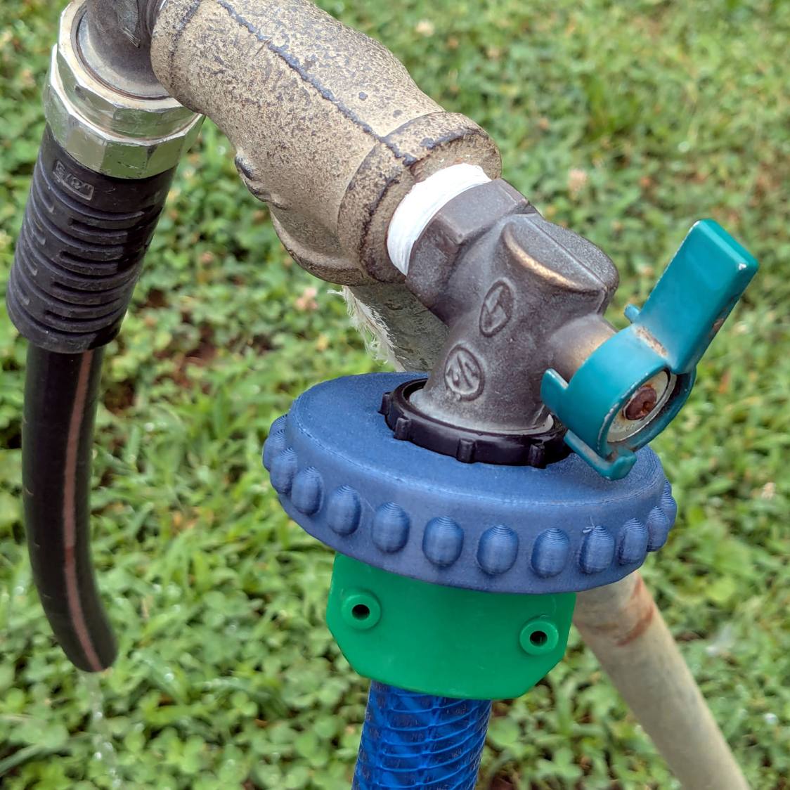
Got it done the day after the old hose split, glued it on the hose with E6000+, installed it the next morning, whereupon the weather delivered three inches of rain. It’ll get screwed onto the faucet in a few days …
This file contains hidden or bidirectional Unicode text that may be interpreted or compiled differently than what appears below. To review, open the file in an editor that reveals hidden Unicode characters.
Learn more about bidirectional Unicode characters
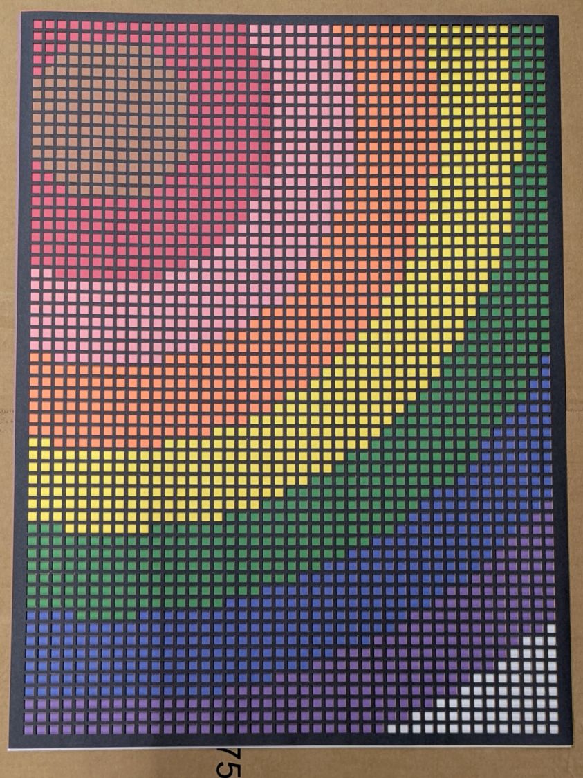
The next step involves creating a corresponding set of LightBurn layouts to burn those holes out of colored paper sheets to produce layered paper art:
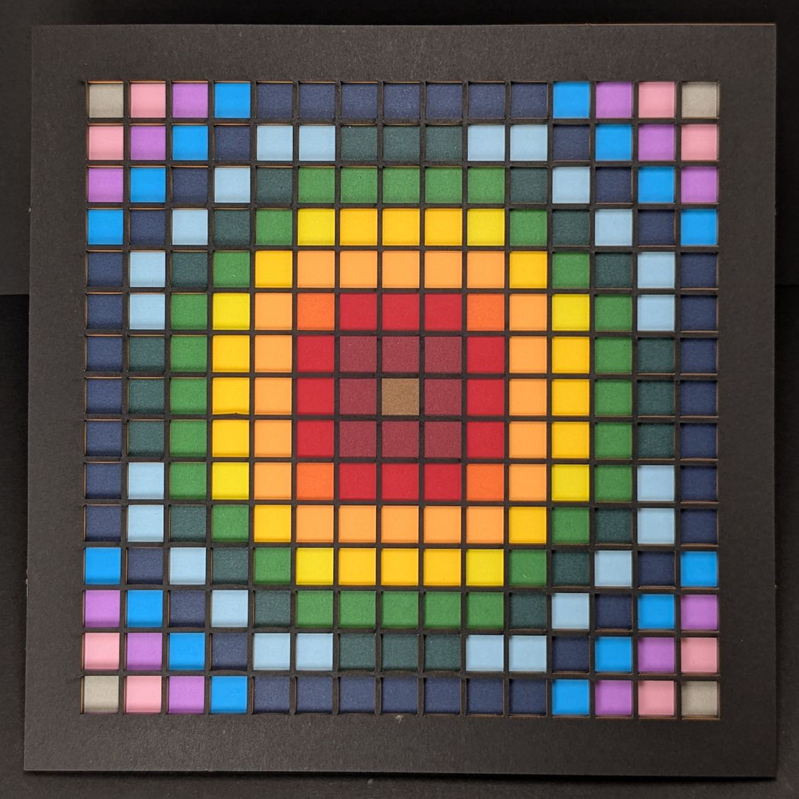
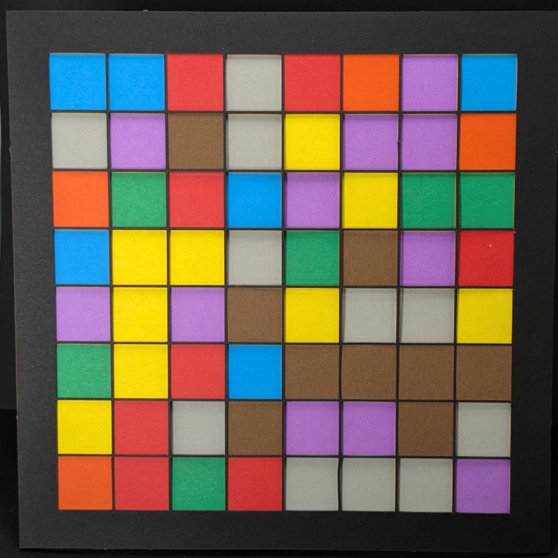
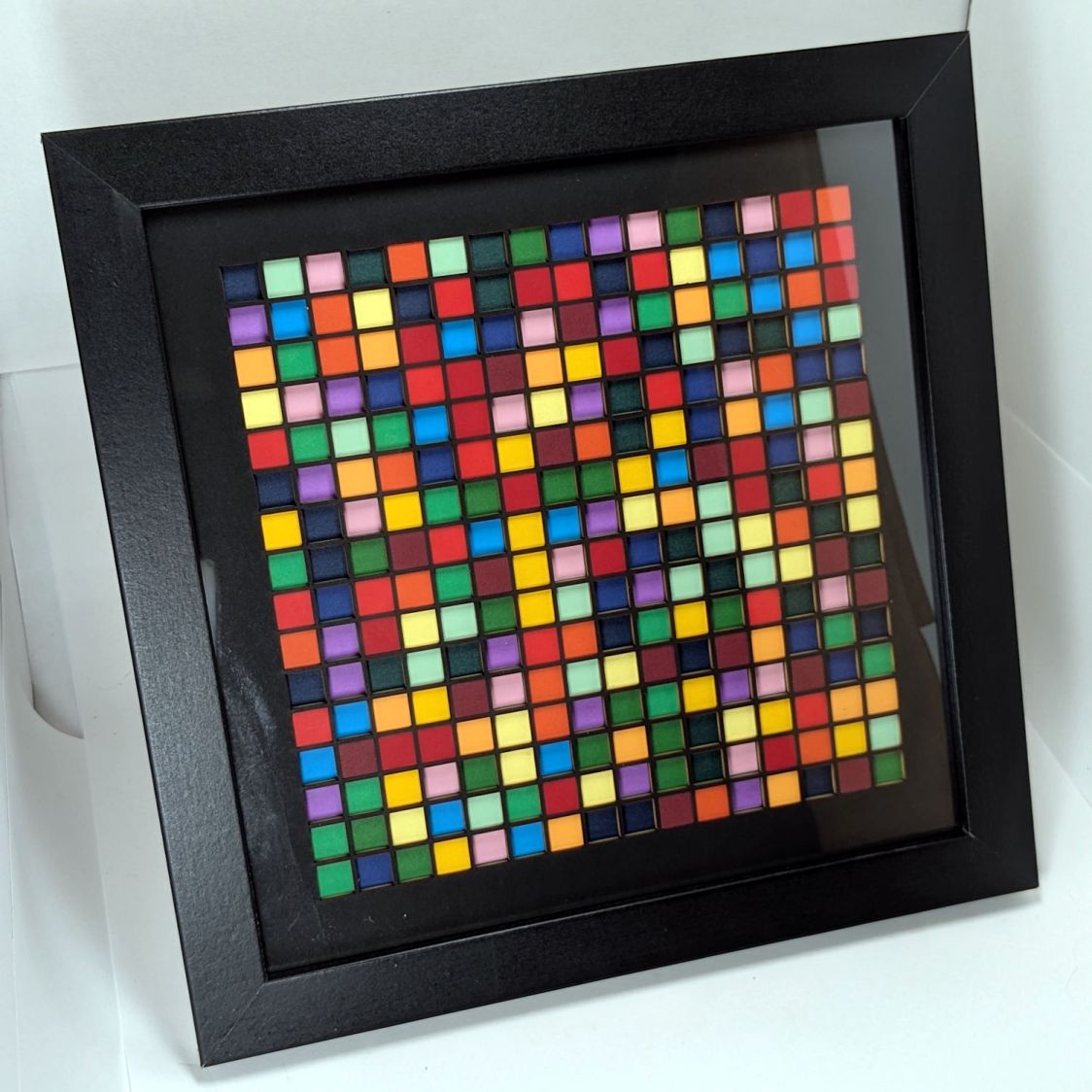
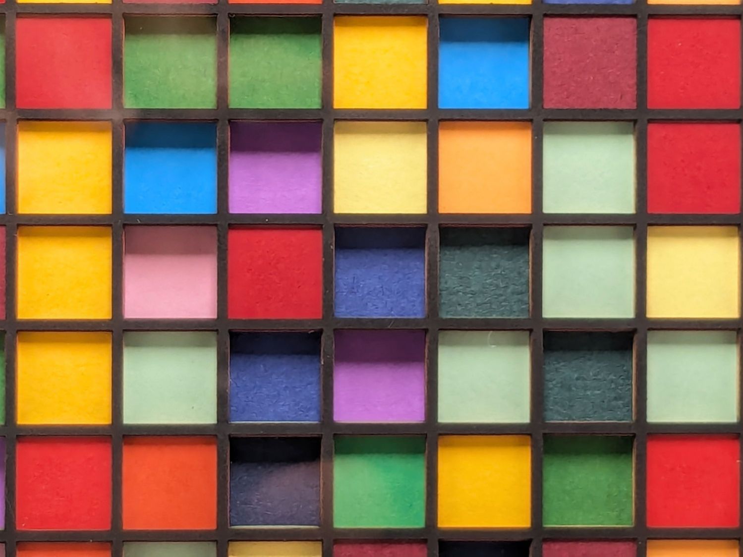
Random Blocks – framed
I know it’s art, because that’s what I was thinking when I made it.
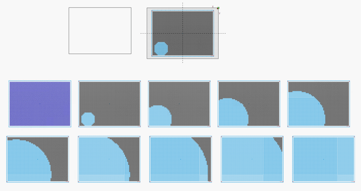
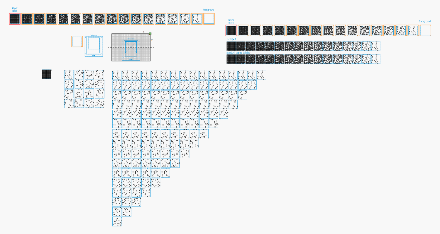
Setting up the LightBurn layouts requires enough manual effort to make the whole thing impractical except as a testcase to see how it all worked out. An overview of the LightBurn workspace:
Random Blocks – 16×16 – LightBurn layout overview
The little bitty grid in the upper left quadrant represents the 700×500 platform of my laser and each of the blue squares is 159 mm on a side. I tend to not delete the intermediate steps, because they serve as some sort of documentation the next time I wonder how I did that thing.
So, we begin.
Import the Inkscape SVG file:
Random Blocks – 16×16 – LightBurn SVG import
The blue outer square and the blue text identifying it are on LightBurn’s T2 tool layer, with the black squares on the C00 layer. All of that happens automagically, because I used colors from the LightBurn palette in Inkscape.
The lonely square in the upper right is the template from which the other 256 squares were cloned, but it has no further purpose in life.
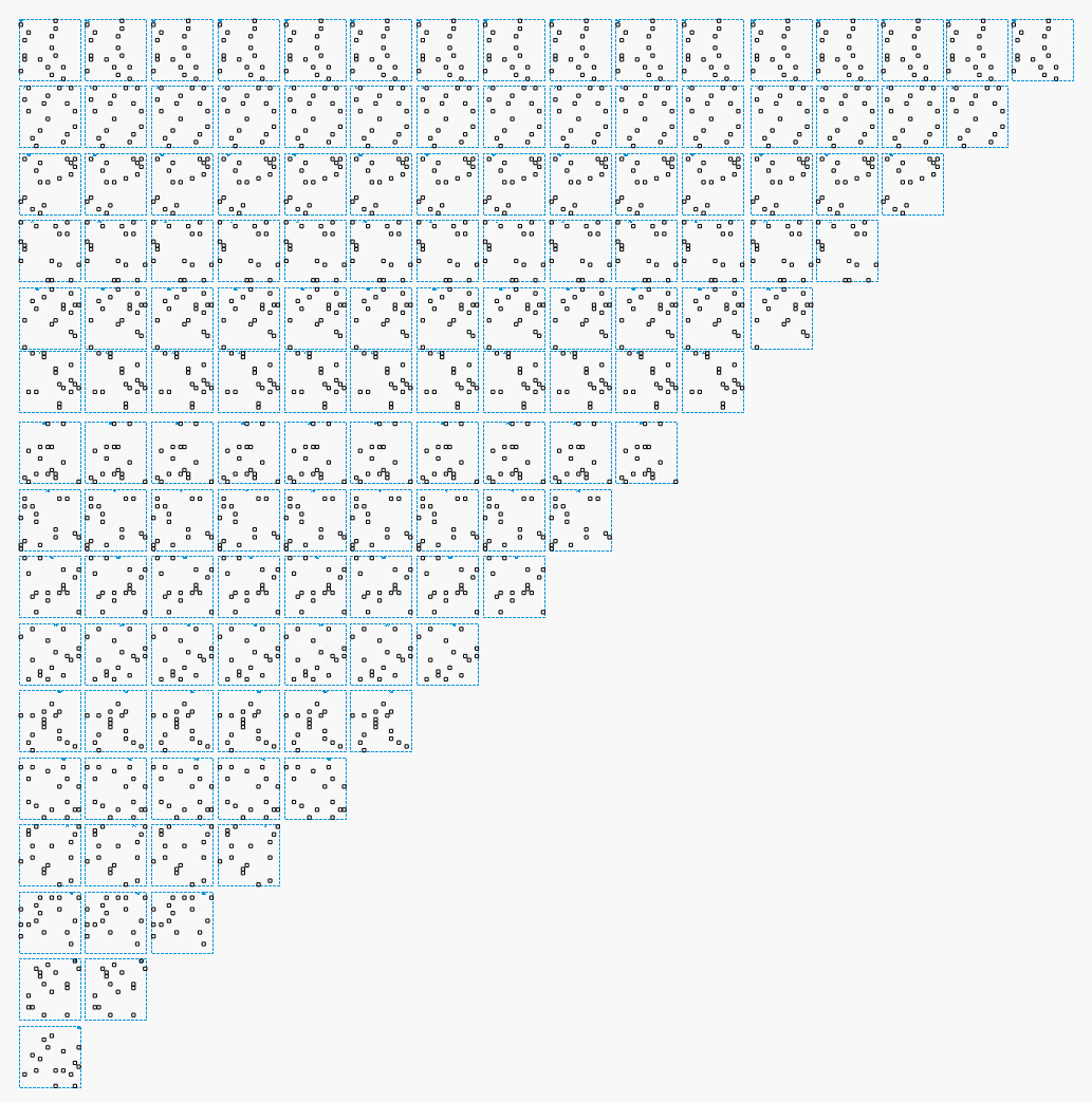
The 16×16 grid consists of sixteen overlaid groups, which need sorting out for ease of access, so drag each one off into a more useful arrangement:
Random Blocks – 16×16 – LightBurn sheet separation
Note that each of the 256 possible positions has a square in only one of those groups.
Each of the 16 groups corresponds to a sheet of paper, with the squares indicating holes exposing the sheet below it. The color of each square, as seen from the top of the stack, comes from the first sheet in the stack without a hole. Perforce, every sheet above the one without a hole must have a hole, which means you must merge all those sheets.
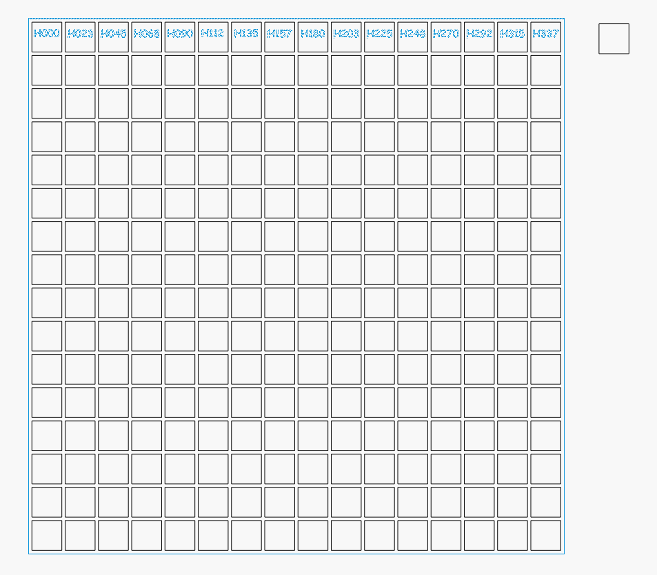
Line up (duplicates of) those 16 groups in the vertical line forming the left column in this arrangement:
Random Blocks – 16×16 – LightBurn array duplication
The top group is the layer I named H000 in Inkscape, with the others in order down to H337 on the bottom. You can see why labeling them is pretty much required.
I should have equalized the vertical spaces between the groups in the left column, but it doesn’t really matter.
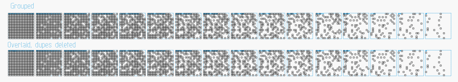
The rest of the triangle comes from duplicating each group using LightBurn’s Grid Array tool with a convenient space between each copy. Make 15 copies of the top group for a total of 16 H000 and no copies of the bottom H337.
Hit Delete Duplicates to get rid of all the overlaid outer squares
If you’re fussy, Duplicate the line of blocks and move it up
Group each block individually to keep all the little squares together with the outline
Thusly:
Random Blocks – 16×16 – LightBurn combined layers
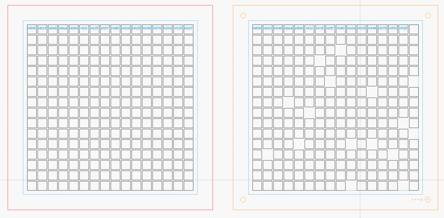
Combine each of those blocks with the sheet cutting template, tweak the binary sheet identification holes, and group the result:
Random Blocks – 16×16 – LightBurn cutting layouts
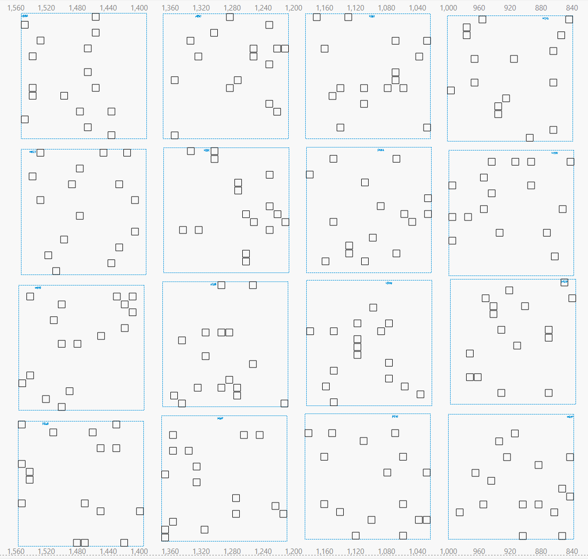
The leftmost block has All The Holes, the next one is missing a few, and so on across the line:
Random Blocks – 16×16 – LightBurn cutting layouts – detail
So the leftmost block corresponds to the black mask atop all the layers. Because it doesn’t have alignment holes in the corners or a binary sheet number, you get to align it by eyeball after gluing up the rest of the stack.
The rightmost block has no cutout squares at all and goes on the bottom of the stack. It also lacks a sheet number, but it’s easy to identify.
Set the LightBurn speed / power values for the layers to cut your stock of colored art paper.
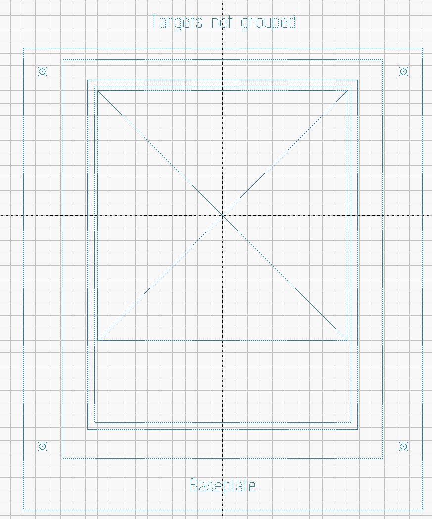
Position the Letter Page Holder template to put the center of the sheet cutout at the center of the platform:
Random Blocks – 16×16 – LightBurn fixture template
Drop the fixture on the platform, use magnets to hold it down, then do a Print and Cut alignment on the corner targets so the template matches the fixture.
Then:
Click to select one of the blocks
Hit Ctrl-D to duplicate it
Hit P to slam it to the middle of the template
Hit Alt-S to Fire The Laser
Hit Del to delete the block
Iterate until done
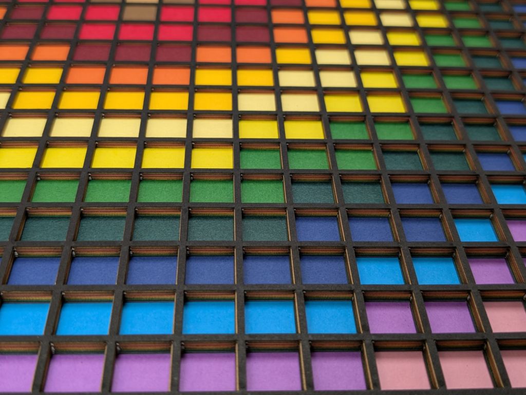
I used a stack of paper in rainbow order roughly corresponding to the Inkscape layer colors, but you could stack them backwards or even use random colors and nobody would ever know:
Random Blocks – framed detail
I kinda like it, but wow that took a lot of prep work …
The random block layered paper design starts as an Inkscape layout, although the amount of manual intervention required to make it happen suggests it’s not really worthwhile. With that in mind, this is how to make it happen …
Draw a 9×9 mm square with these properties:
Undefined fill: each block will become different
Flat color stroke set to black with 100% alpha
0.2 mm stroke width: so LightBurn will see it
Because the squares will be on 10 mm centers, draw a 159 mm square:
Align the big square on the grid, which should have 10 mm spacing because that’s convenient. This will become the way you align the array of squares in the LightBurn layout, so you really want the array to fit neatly and symmetrically inside the 159 mm square.
Iterate 16 times, all in T2 layer color:
Create a layer with a name like H000 through H337
Create a corresponding text string
Align fussily
Duplicate the 159 mm square
Put the block and the text string on the new layer
Lock the square and text so they can’t move
Which will look like this:
Random Blocks – 16×16 159mm – Inkscape layer labels
Unlike LightBurn, the color is not linked directly to the layer, so each of those text strings is on the corresponding named layer and there are 16 duplicates of the large box at exactly the same coordinates. Plus the original 159 mm square, which remains unlabeled and unlocked.
Select the black 9 mm block and create a 16×16 clone army array:
Random Blocks – 16×16 159mm – Inkscape clone setup
The Initial Color is critical:
Random Blocks – 16×16 159mm – Inkscape clone color
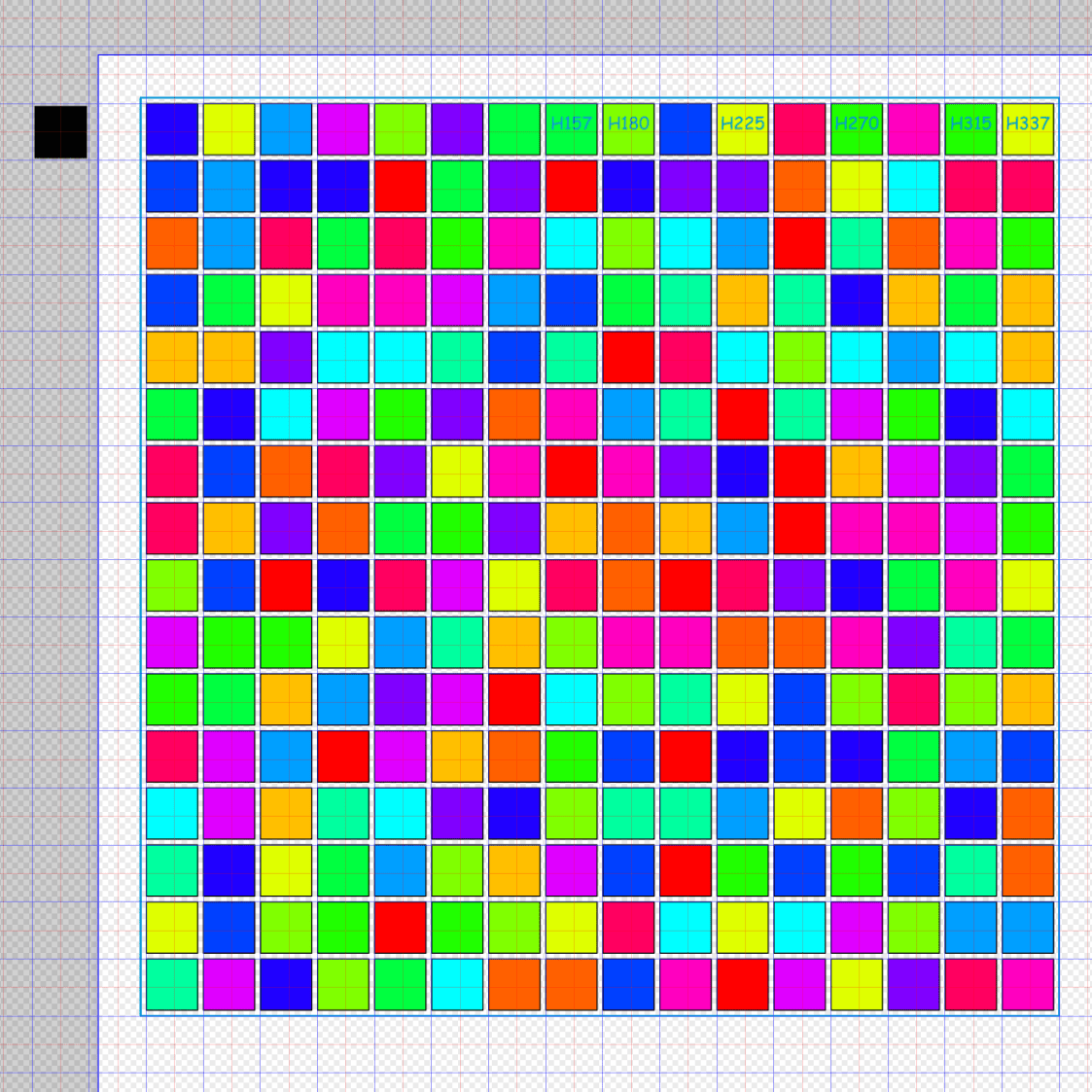
The layer names come from the 6.25% hue steps, starting with H=0, which will look like this:
Random Blocks – 16×16 159mm – Inkscape hue steps
Note that LightBurn absolutely does not care about the colors. All it will get is the outlines corresponding to the strokes, with the colors collecting them into separate groups for the paper layers.
Go to the Layers window, select the original block (which is likely on Layer 1 or some such), cut it, and paste it somewhere outside the 159 mm square where it won’t cause any trouble.
Iterate 16 times in the Layers window:
Select one of the 256 clone squares, which will have an automagic name like use1272
Right-click, hit Select Same → Fill Color
Right-click, hit Move to Layer …
Pick the layer name matching the hue
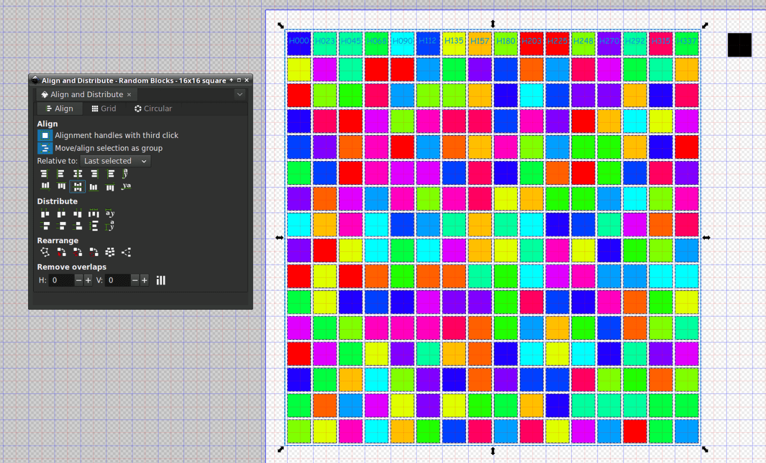
Select all the squares and Distribute randomly:
Random Blocks – 16×16 159mm – Inkscape rearrange
Then Align them in a grid:
Random Blocks – 16×16 159mm – Inkscape grid distribute
The 0.8 mm Spacing is the distance between 9 mm blocks with 0.2 mm strokes.
Shift-click on the 159 mm square to add it to the selection, then hit the two center-align buttons to center the 16×16 array in the square:
Random Blocks – 16×16 159mm – Inkscape center align
Save that sucker as an Inkscape SVG and it’s ready to import into lightBurn.
With all that done, you can generate different random layouts by:
Select the existing 16×16 array (but not the outer 159 mm square; Undo is your friend)
Randomize the array
Align it
Center it
The colored blocks remain in their corresponding layers, so you need not go through all that overhead ever again.
Whether that’s worthwhile is up for grabs, but now I have a faint chance of getting it right the next time.
I wanted to see / feel what 18 paper layers would look & feel like:
Random Blocks – framed
That’s a black mask layer atop 16 cut layers of cheerful colored paper in rainbow order and a solid purple sheet at the bottom:
Random Blocks – framed detail
The layer runs at 100 mm/s with 20% of a 60 W laser. The relatively low speed, combined with right-angle corners, produces very crisp results unlike the rounded-corner Subpixel holes.
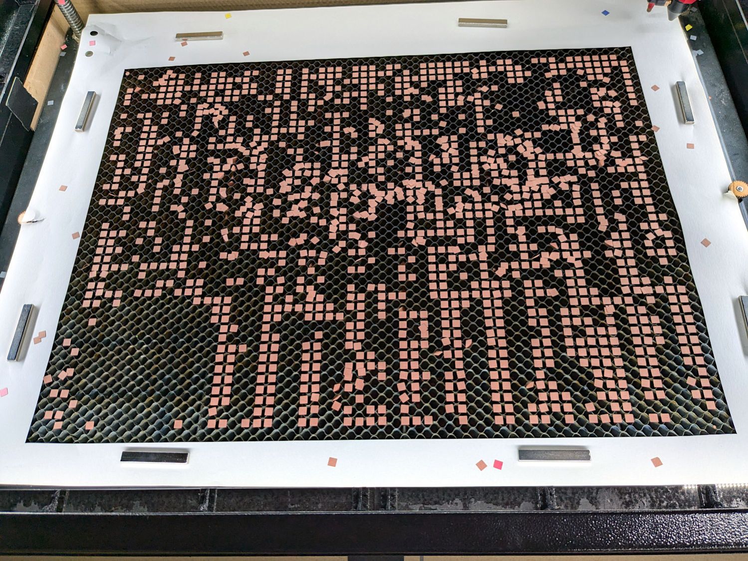
The holes form a 16×16 grid and cutting the first few layers with 250-ish holes takes a bit under three minutes apiece:
Random Blocks – cutting red layer
The sheets sit in the Letter sheet fixture and get four round holes in the corners for the assembly fixture, plus a binary sheet ID helping me with the stacking order:
Random Blocks – assembly process
The hole patterns come from Inkscape through LightBurn, in a grindingly intricate manual process crying out for automation. This is a feasibility study to see if the result is worthwhile and, yeah, it looks promising. More about all that later.
If someone had asked Young Me what I’d be doing in half a century, dabbing colored paper with a glue stick would not have been one of my choices and not just because glue sticks hadn’t been invented back then.
Another couple of years and I’ll be ready for the Activity Room at the Olde Folkes Home.