Ed Nisley's Blog: Shop notes, electronics, firmware, machinery, 3D printing, laser cuttery, and curiosities. Contents: 100% human thinking, 0% AI slop.
Category: Software
General-purpose computers doing something specific
My Fitbit Charge 5 has become fussy about its exact position while snapped to its magnetic charger, so I thought elevating it above the usual clutter might improve its disposition:
FitBit Charge 5 stand – installed
The Charge 5 now snaps firmly onto its charger, the two power pins make solid contact, and it charges just like it used to.
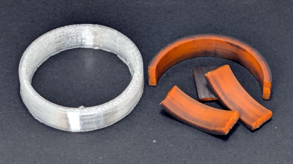
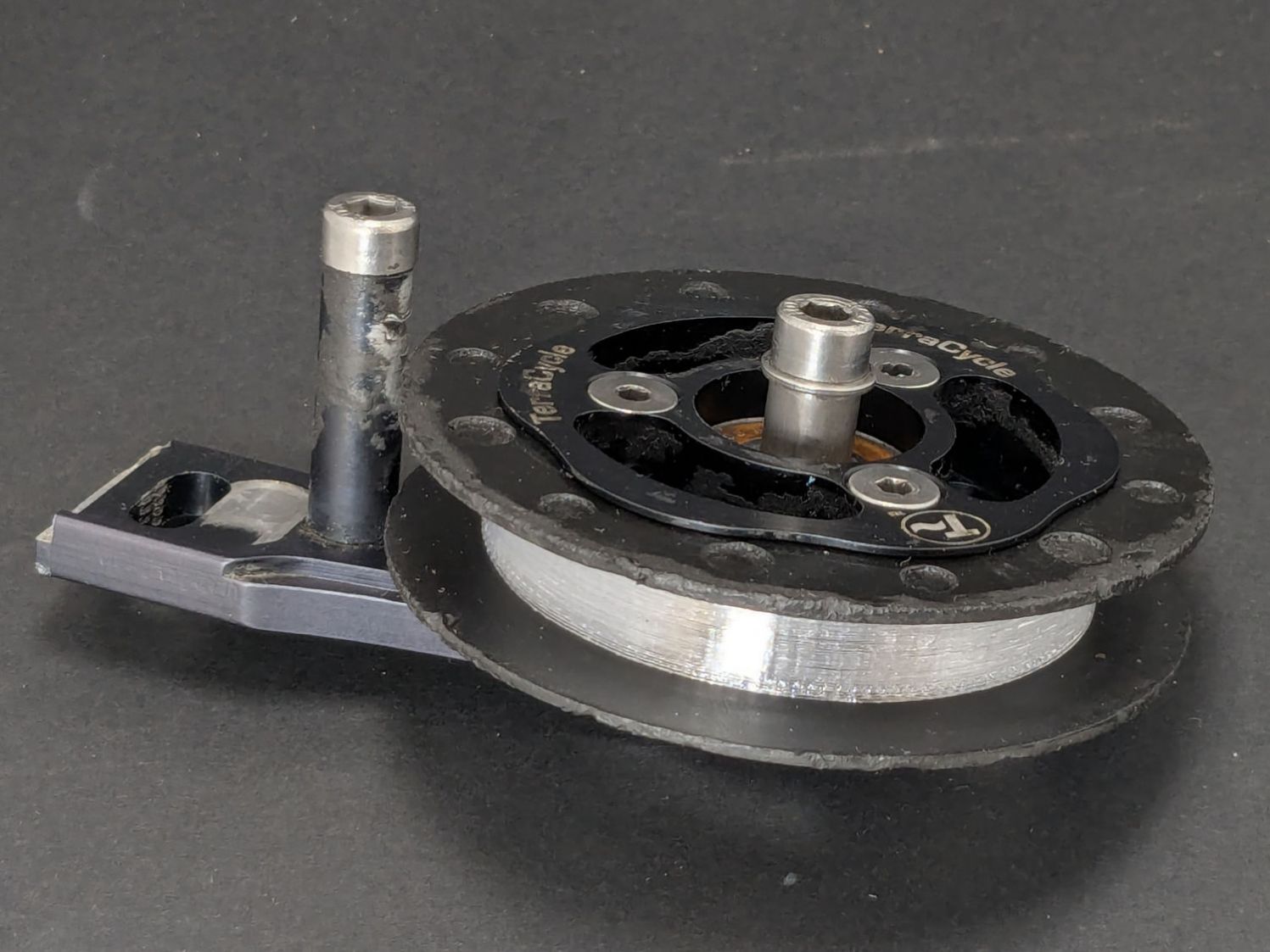
The Terracycle (now T-cycle, for reasons presumably involving the transfer of money) chain return idlers on our Tour Easy bikes developed hardening of their urethane tires:
Terracycle Idler tire – printed vs OEM
Urethane shouldn’t crack like that, but after more than fifteen years, stuff wears out.
The white ring is 95A TPU printed on the Makergear M2, which is definitely more flexy than the original tire, but has the redeeming feature of being both Good Enough and trivially easy to model:
include <BOSL2/std.scad>

NumSides = 4*3*2*4;
$fn=NumSides;

Thick = 3.5;
ID = 46.4;
OD = ID + 2*Thick;
Length = 11.2;

tube(Length,id=ID,od=OD,anchor=BOTTOM);
It printed with 5 mm brims on both the ID and OD, because TPU has the barest adhesion to the M2’s glass plate + hair glue. There’s a long-unopened box now on the bench with a BuildTak PEI surface (thank you: you know who you are!) that should improve the situation.
In any event, the tires fit well:
Terracycle Idler tire – installed
The layer-to-layer adhesion isn’t as good as I think it should be, so I’ll likely use those tires as testcases for tweaking the new build plate & settings.
The motivation for making Yet Another Coaster was to see if combining a few techniques I’ve recently learned would produce a nicer result.
Spoiler: Yup, with more to be learned and practiced.
This is a somewhat nonlinear narrative reminding me of things to do and not do in the future, so don’t treat it as a direct how-to set of instructions.
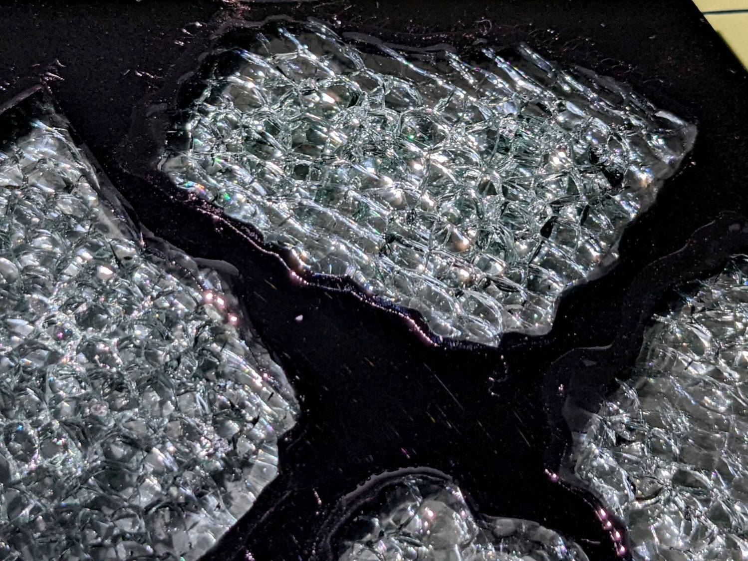
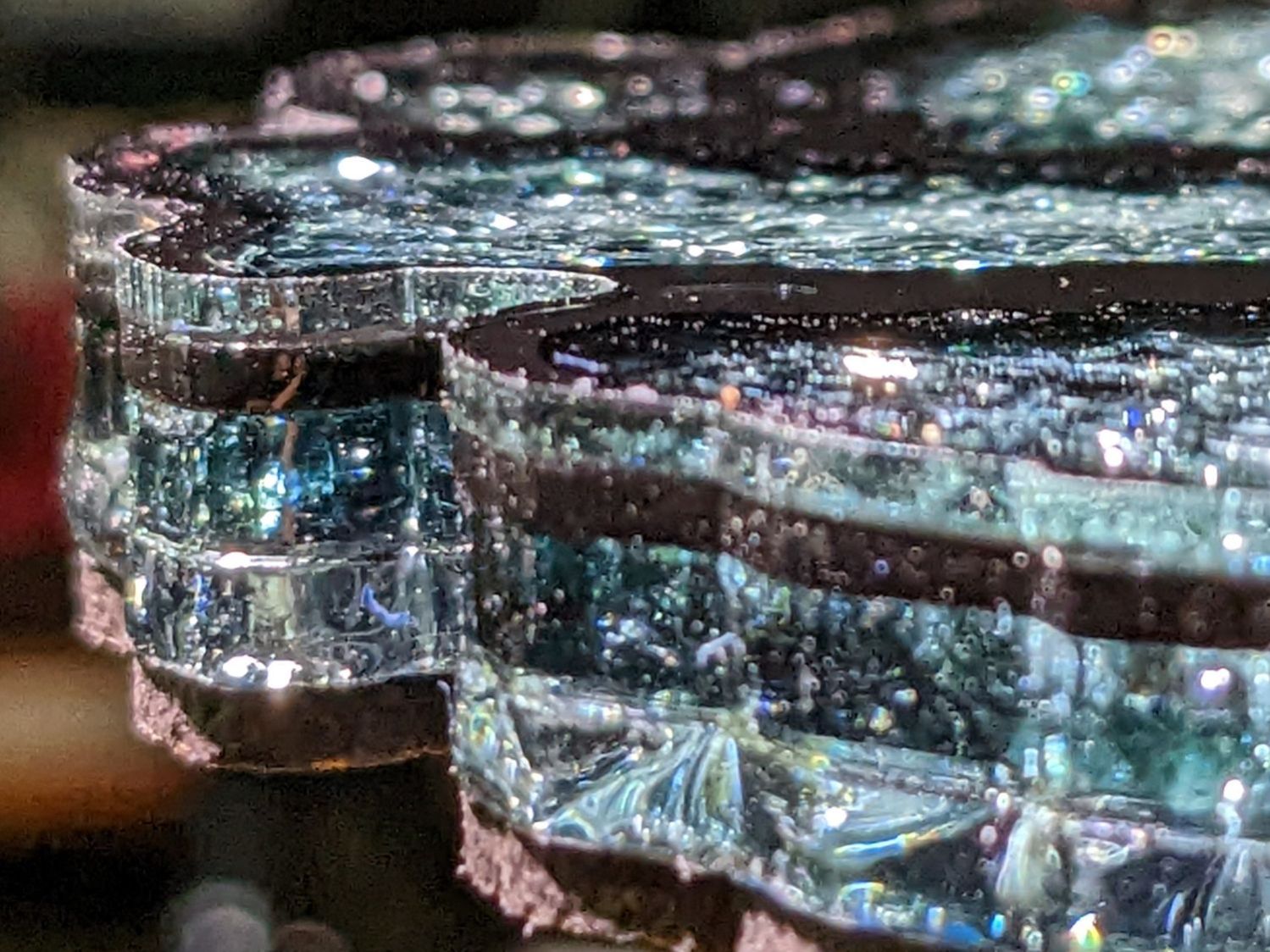
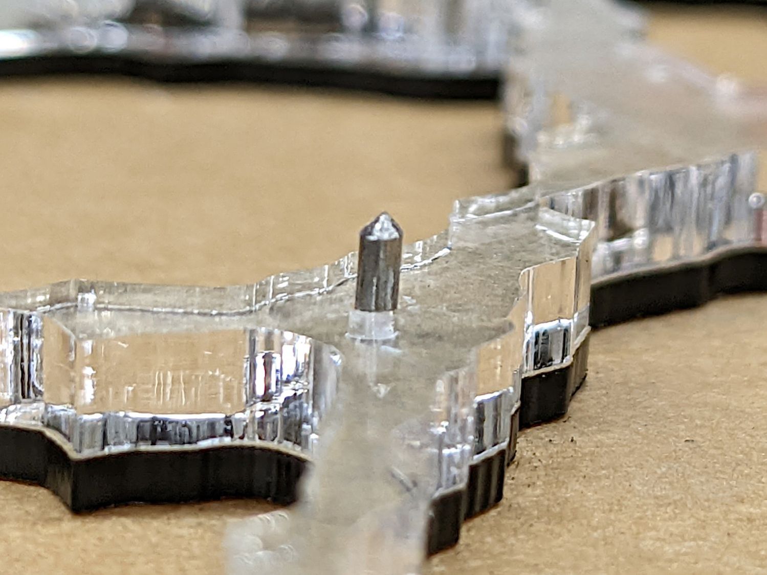
The glass fragments sit inside holes in the next two (or three or whatever) acrylic layers, which must have a total thicknesses slightly more than the glass thickness andremain properly aligned while assembling the whole stack:
Smashed Glass Coaster 5 – alignment pin
Bonus: all that cutting generates an absurd amount of acrylic scrap. I eventually put much of it to good use, but not producing it in the first place would be a Good Thing …
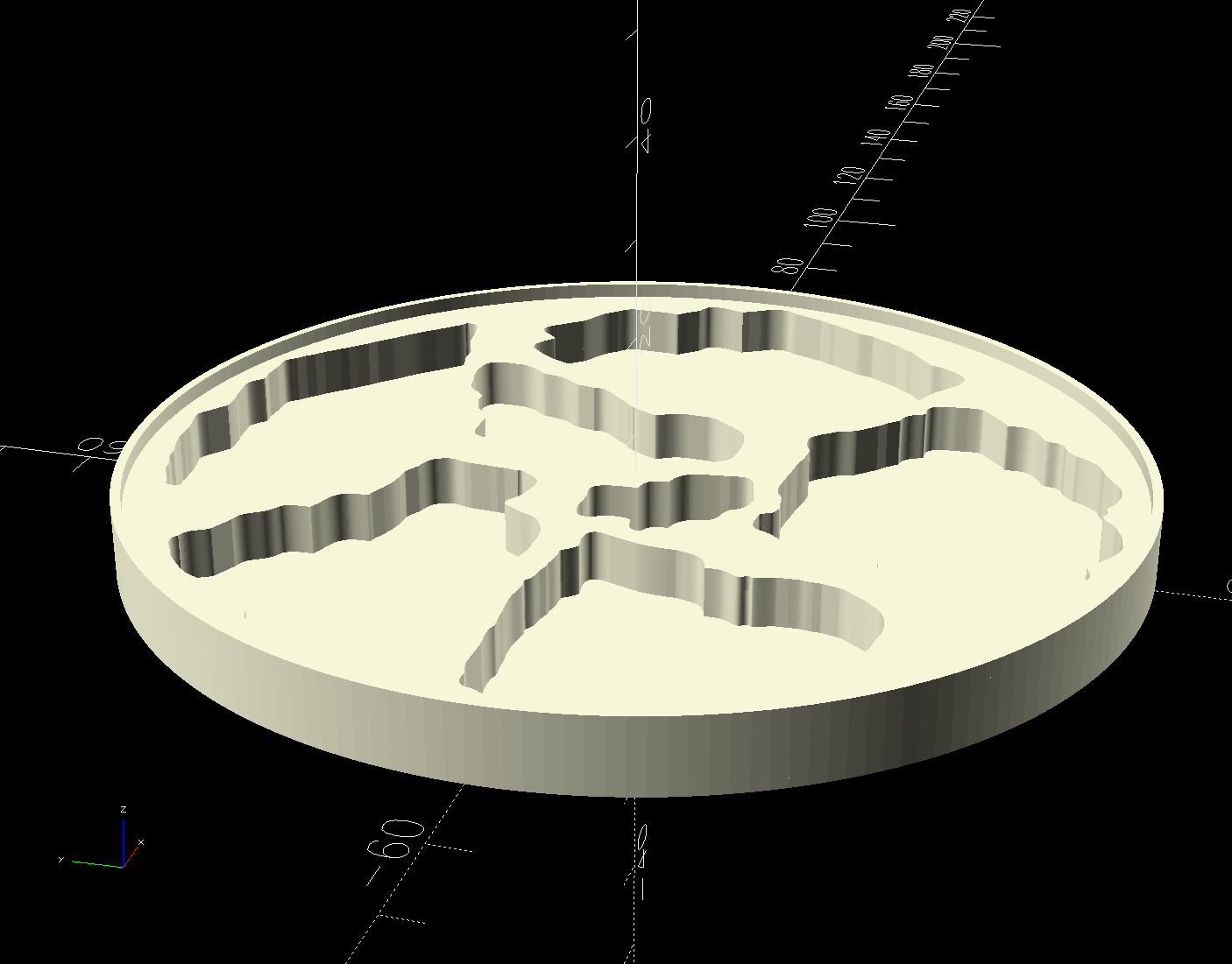
So 3D print the entire base, which requires generating a solid model with recesses for the fragments:
Printed Coaster Layout – solid model
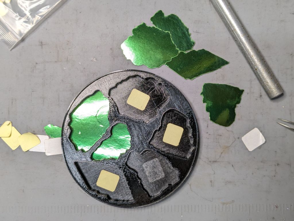
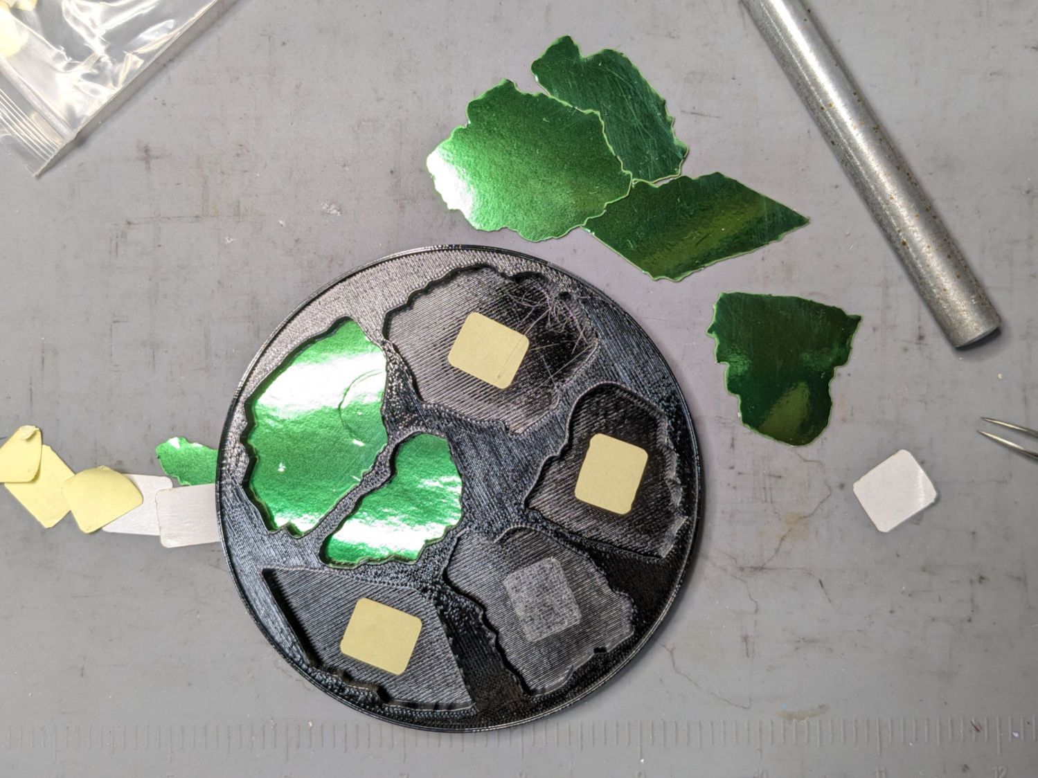
Because there’s no real justification for an optical-quality mirror under smashed glass, use reflective metallized paper in the recesses as reflectors:
Smashed glass printed coaster – metallized paper assembly
The glass is more-or-less greenish-blueish, so I used a strip of green metallized paper that made the glass fragments green. Obviously there’s some room for choice down there.
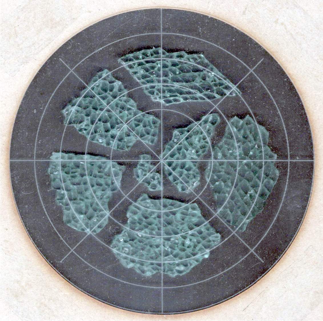
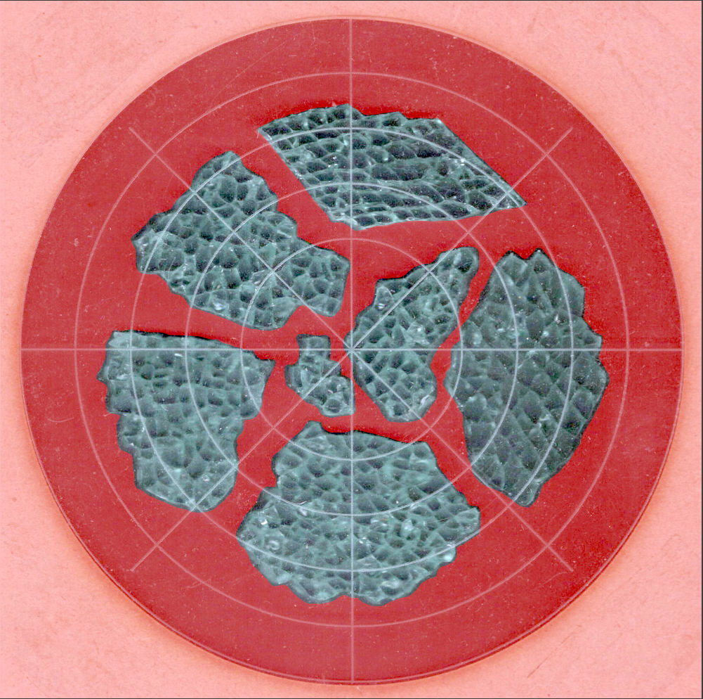
Both the base and the reflectors use outlines of the fragments, so I started with a scan of the approximate layout in GIMP:
Smashed Glass – 4in – group A – tweaked
I traced the outline of each fragment using the Scissors Select Tool, which lays line segments along the sharpest gradient between clicked points, then switched into Quick Mask mode to adjust & smooth the results:
Smashed Glass paths – quick mask
That’s the result after sketching & saving all the paths as separate SVG files to allow importing them individually into InkScape, OpenSCAD, and LightBurn.
Which turned out to be suboptimal, as it let me write an off-by-one blooper omitting the last file from the OpenSCAD model:
A better choice puts all the paths into a single named group, saved as a single SVG file, then importing that group from the file using its name, along these lines:
It’s not clear if I can do that directly from GIMP by saving all the paths in a single file, then importing that lump into Inkscape as a group, but it’ll go something like that.
After getting the fragment paths into Inkscape, add a 0.5 mm offset to each path to clear any non-vertical edges. This will be checked with the template cut using LightBurn as described below.
Add a 1 mm rim around the outside, with the 4 inch OD matching the usual PSA cork base:
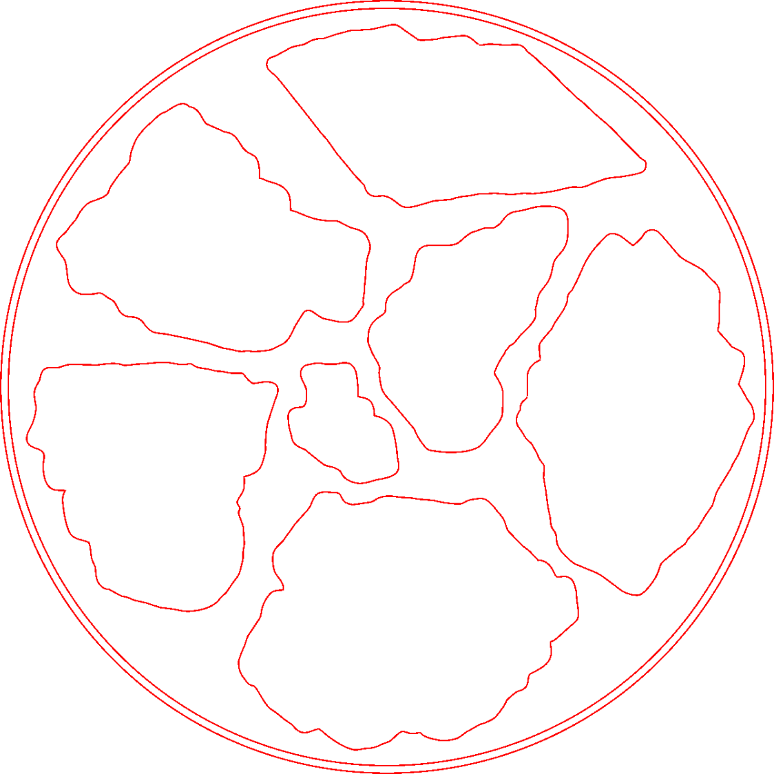
Fragment layout – 4in
Now’s the time to nudge / rotate the outlines so they have at least a millimeter of clearance on all sides / ends, because that’s about as thin a section of printed plastic as you want.
Locating the center of the OD (and, thus, everything inside) at the lower-left corner of the Inkscape page will put them at the OpenSCAD origin. I have set Inkscape to have its origin at the lower left, rather than the default upper left, so your origin may vary.
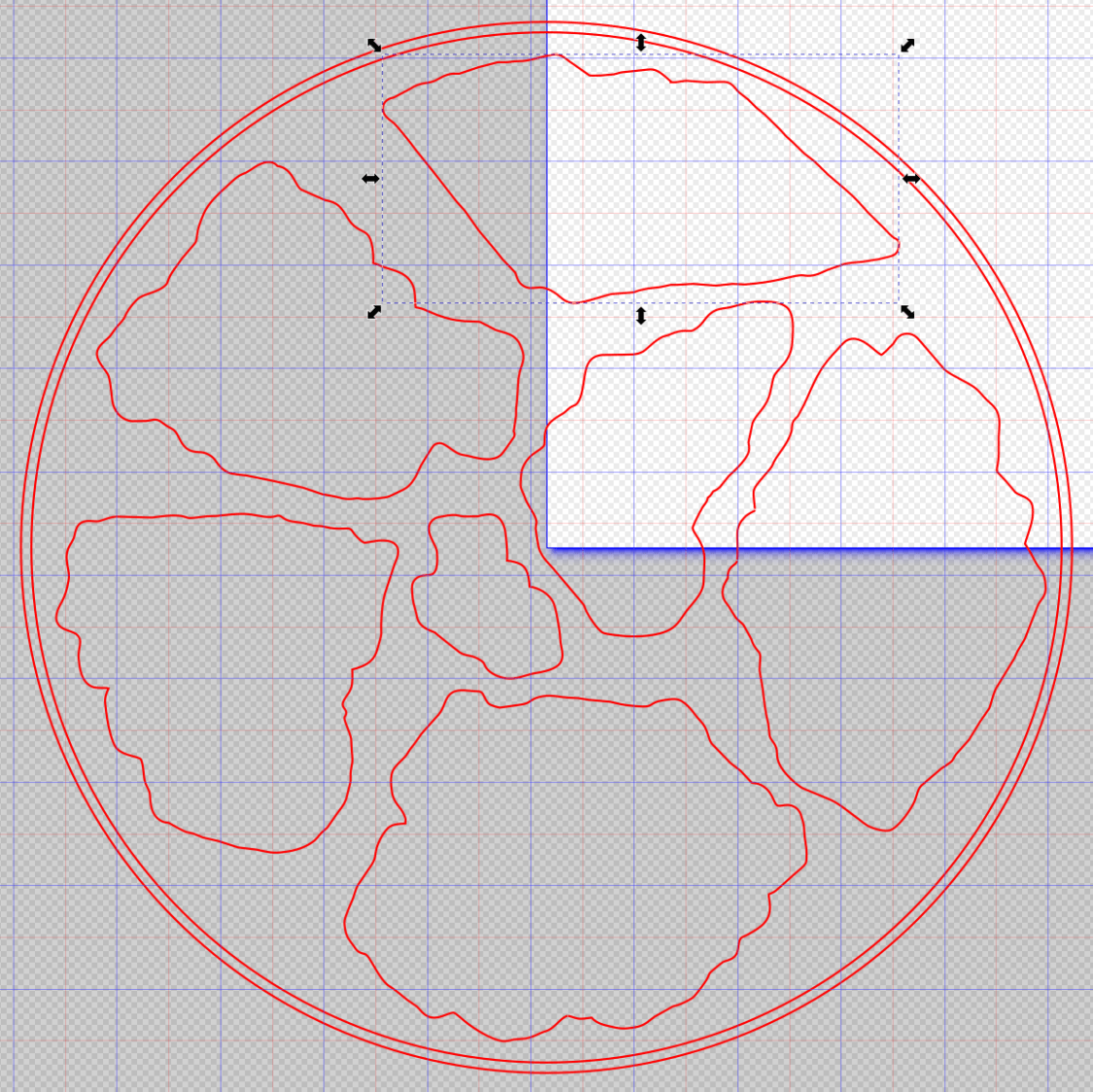
Select one of the paths:
Fragment layout – Inkscape A
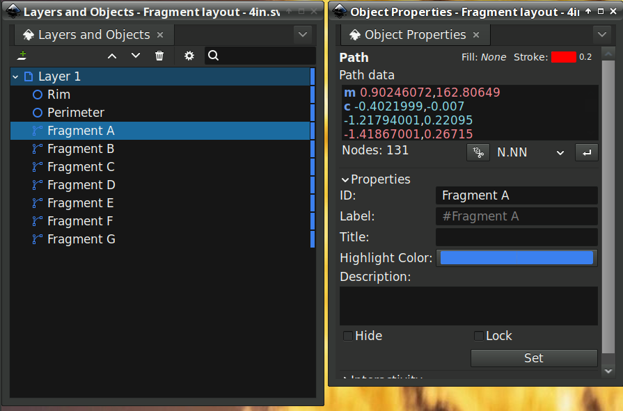
Then set the ID in its Object Properties:
Fragment layout – Inkscape A – properties
There is an interaction between the name over in the Layers and Objects window, which apparently comes from the GIMP path name for the imported fragments, and the resulting ID and Label in the Object Properties window. However, renaming an object on the left, as for the Rim and Perimeter circles, does not set their ID or Label on the right. Obviously, I have more learning to do before this goes smoothly.
With everything laid out and named and saved in an SVG file, the OpenSCAD program is straightforward (and now imports all the fragments):
Which squirts out the solid model appearing above.
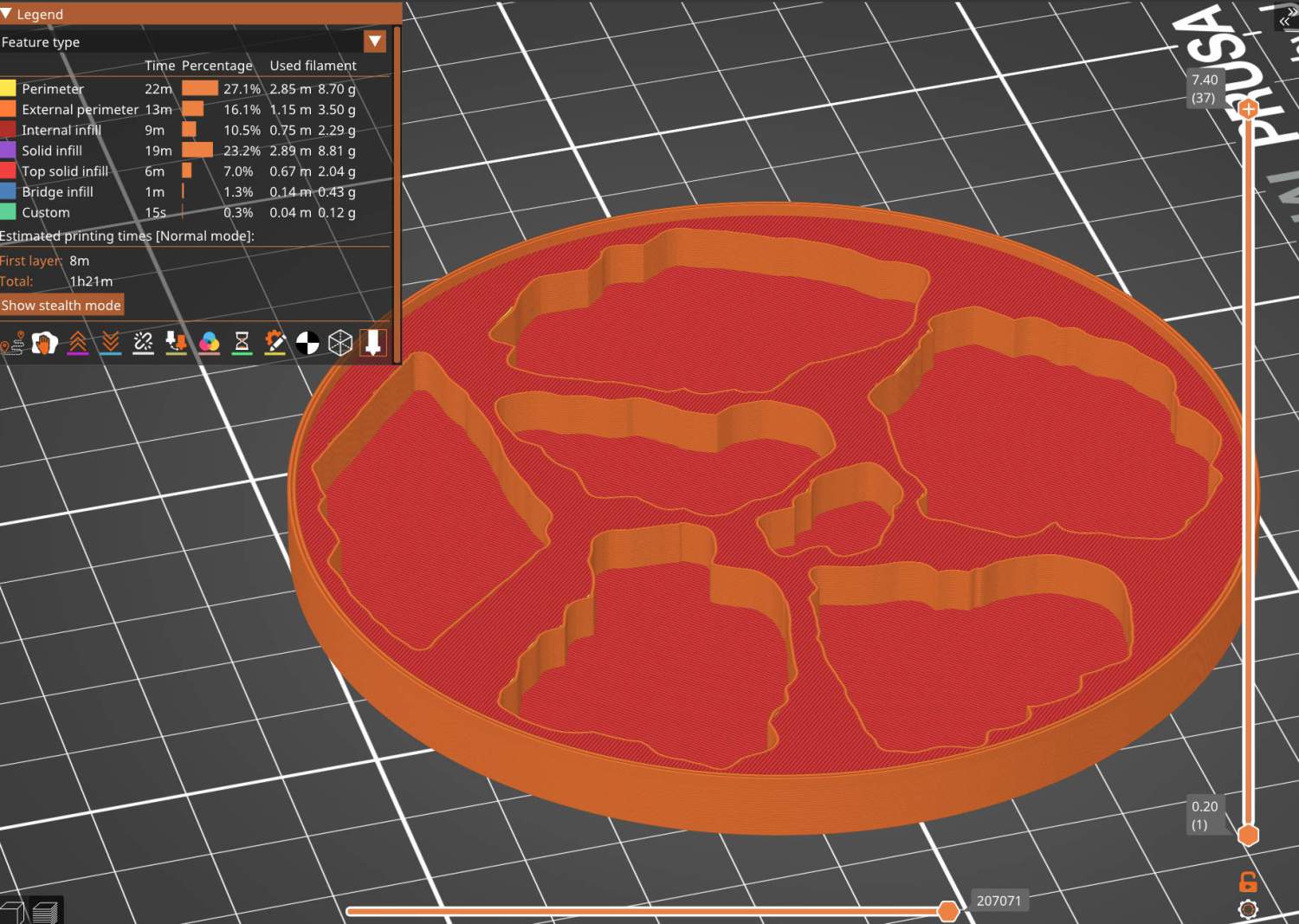
Feeding it into PrusaSlicer turns the model into something printable:
Printed Coaster Layout – slicer
And after supper I had one in my hands.
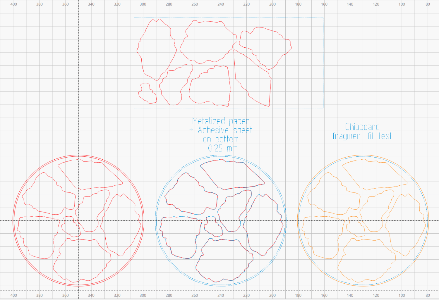
Before doing that, however, import the same SVG file into LightBurn, as on the left:
Printed Coaster Layout – LightBurn
On the right, duplicate it, put the inner Rim on a tool layer, put the rest on a layer set to cut chipboard, and make a template to verify those holes fit around the fragments:
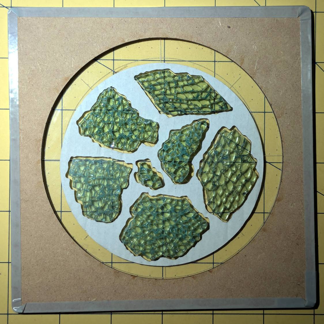
Smashed glass printed coaster – fragment test fit
Which a few didn’t, explaining why I go to all that trouble. Iterate through GIMP → paths → SVG → Inkscape → LightBurn until it’s all good. Obviously, you do this before you get too far into OpenSCAD, but they all derive from the Inkscape layout, so there’s not a lot of wasted motion.
The middle LightBurn layout insets the fragment outlines by 0.25 mm to ensure the paper fits easily and puts them on a layer set to cut metallized paper. Those fragments then get duplicated and rearranged within the rectangle on the top to fit a strip of metallized paper from the scrap box. Fire The Laser to cut them out and stick them to the bottom of their corresponding 3D printed recesses with leftover snippets of craft adhesive sheet as shown above.
I had originally intended to cover the bottom of the entire sheet of metallized paper with an adhesive sheet, but realized the whole affair was going to be submerged in epoxy, so just making sure the paper didn’t float away would suffice.
Which looks OK-ish, although not significantly different from the straight-hole versions:
Layered Paper – tapered blocks
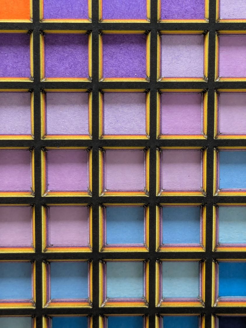
The taper shows off the layer colors along the sides of the holes:
Layered Paper – tapered blocks – oblique detail
Unfortunately, it also makes the corner blemishes painfully obvious:
Layered Paper – tapered blocks – detail
My first attempt didn’t skootch the squares over by the size of the inset, thus neatly aligning the upper left corners and giving the bottom right corners twice the inset:
Layered Paper – tapered blocks – fixed origin – detail
Which made those gnarly corners painfully obvious.
I tried stacking the sheets with their bottom side upward, hoping to disguise the edge charring, but to no avail.
The inset code remains in place with a default of zero:
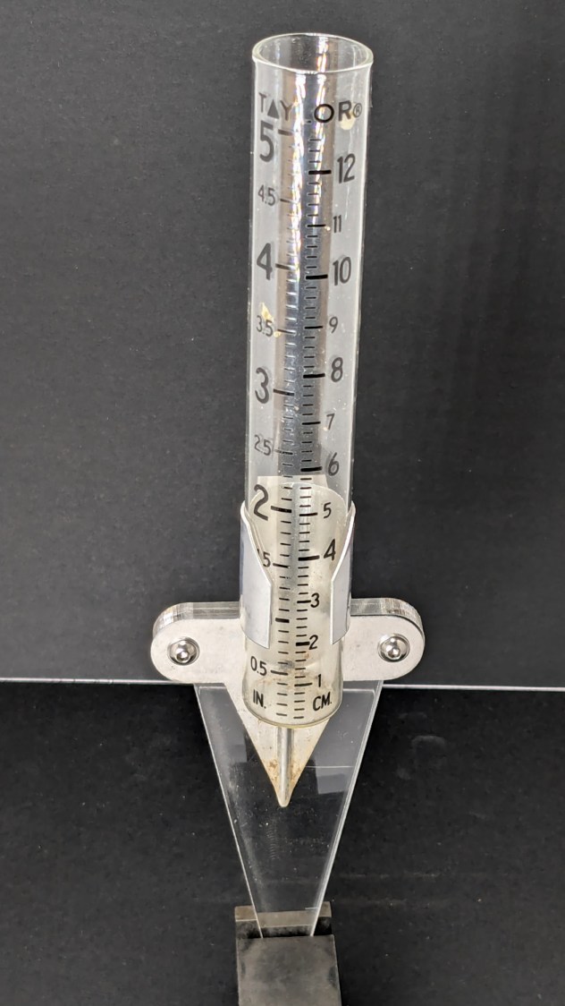
One of Mary’s gardening buddies gave her a Taylor rain gauge he picked up at a closeout sale, but the exceedingly thin aluminum holder obviously wasn’t up to the task:
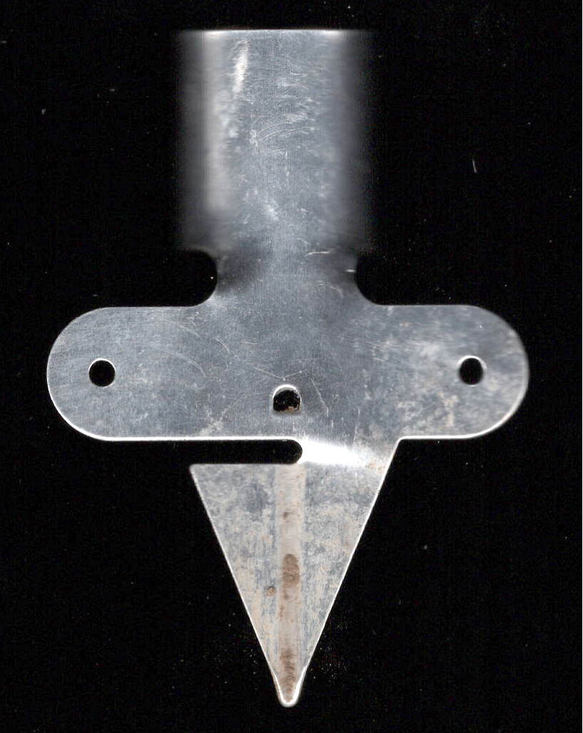
Taylor Rain Gauge – OEM metal stake
I briefly considered 3D printing a better bracket, but came to my senses:
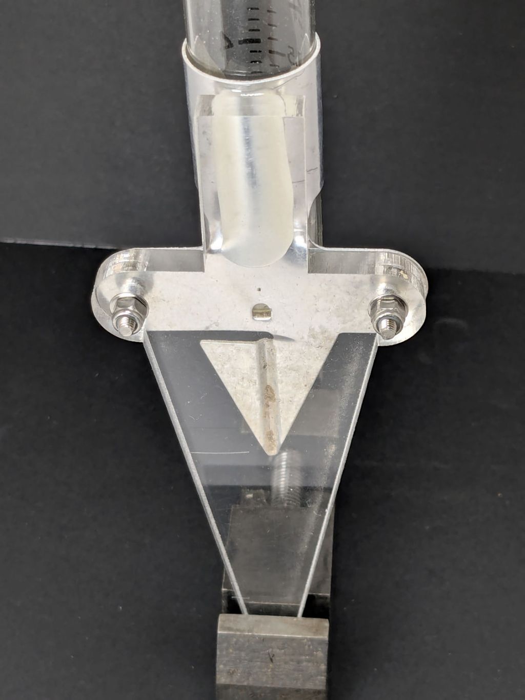
Taylor Rain Gauge holder – front
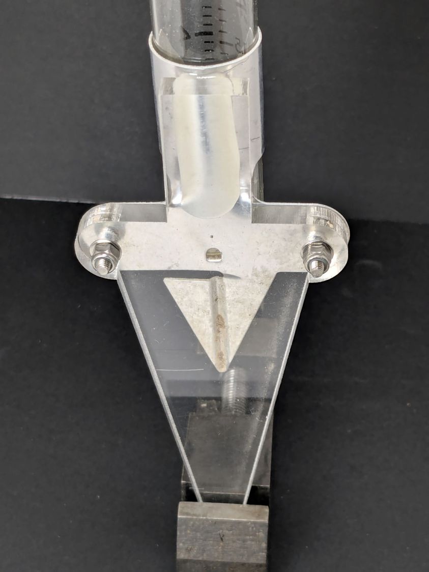
A generous fillet of tan JB PlasticBonder holds the thin aluminum clamp ring to the top of the dagger spike:
Taylor Rain Gauge holder – rear
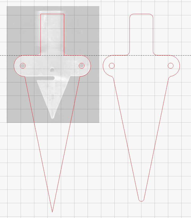
The spike is 6.3 mm acrylic and should survive for a while despite the stress-raiser corners. The next iteration will have radiused corners and could last longer:
Taylor Rain Gauge Holder – LightBurn layout
The holes will fit 4 mm screws, although the OEM holder isn’t good for more than 3 mm.
Having just replaced the shower faucet cartridge, the knob insert (probably from 1998, according to a label on the shower stall) could also use some improvement:
Delta 1400 Shower Faucet knob insert – front
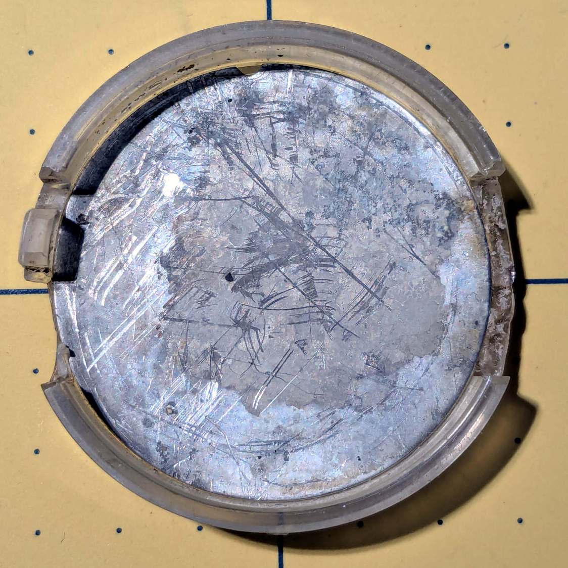
That oblong blue tint is water. The shattered sections formerly had small fingers holding the insert into the knob:
Delta 1400 Shower Faucet knob insert – rear
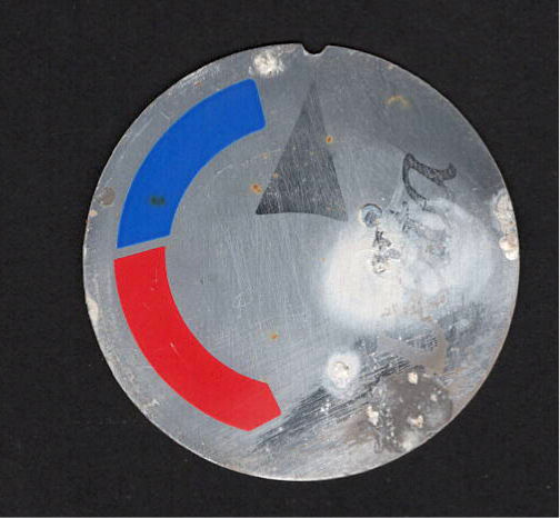
Pry the aluminum disk out of the insert and scan it:
Delta Shower Faucet – label scan
There is no feature in the knob to capture the semicircular notch at the arrow tip, so the disk can rotate as it pleases. I think the arrow should point to the OFF label on the bezel when the water is turned off, but who knows?
Import it into Inkscape, whereupon it becomes obvious the printed legend is not centered on the disk, lay suitable construction lines & circles, then draw similar shapes:
Delta Shower Faucet – Inkscape layout
I located the circles at the Inkscape page corner to put their center at the (0,0) origin with the arrow pointed along the X axis to simplify importing it into OpenSCAD.
The three useful graphic features go on separate layers so OpenSCAD can treat them as separate objects:
The KnobAngle rotation comes from the angle of the features inside the knob that locate the insert, which are aligned horizontally here, but at about 30° when the knob is installed on the faucet :
Delta 1400 Shower Faucet knob – insert recess features
The knob shined up surprisingly well for being three decades old; that photo is as-found.
Import the Inkscape graphics into OpenSCAD and align them an itsy above the top of the insert structure to prevent Z fighting without triggering the slicer into adding another layer:
Those three shapes must be handled separately, lest OpenSCAD combine them into one thing that PrusaSlicer won’t recognize as distinct shapes. There’s no need to subtract them from the main insert shape, but getting separate colors to come out right is definitely not straightforward.
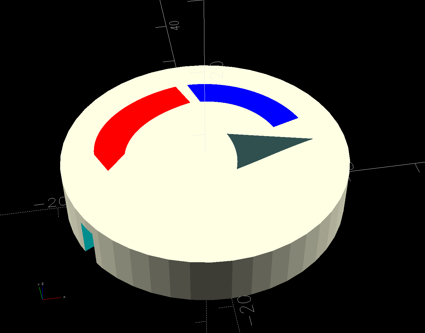
Which looks like this, with cheerful colors that need not correspond to the printer filaments:
Delta Shower Faucet Insert – solid model
Normally I have a set of Build transformations to orient the thing for printing, but doing a simple rotation to put the top down on the platform also blows away the separate nature of the graphics.
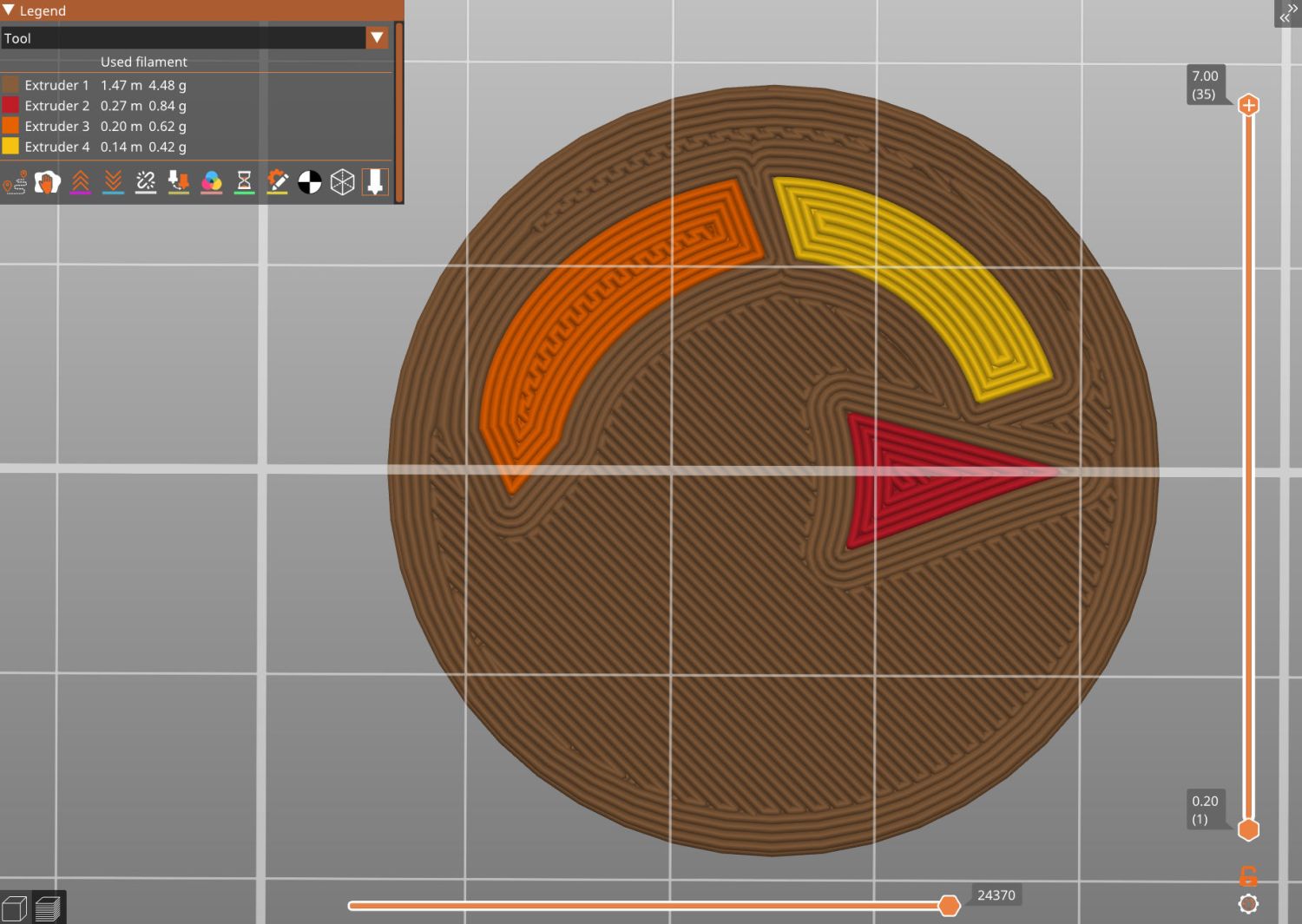
I use the EIA color code sequence in PrusaSlicer so I can identify the filament number by eye:
Shower Fauce Knob Insert – PrusaSlicer preview
A little while later:
Delta 1400 Shower Faucet knob insert – installed
The insert is a loose fit in the knob, held in place by good double-sided foam tape to the screw securing the knob. I decided to not bother with little fingers, because I loves me some simple removable adhesive action.
Yeah, you can buy an entire replacement knob for ten bucks, but where’s the fun in that?
This file contains hidden or bidirectional Unicode text that may be interpreted or compiled differently than what appears below. To review, open the file in an editor that reveals hidden Unicode characters.
Learn more about bidirectional Unicode characters
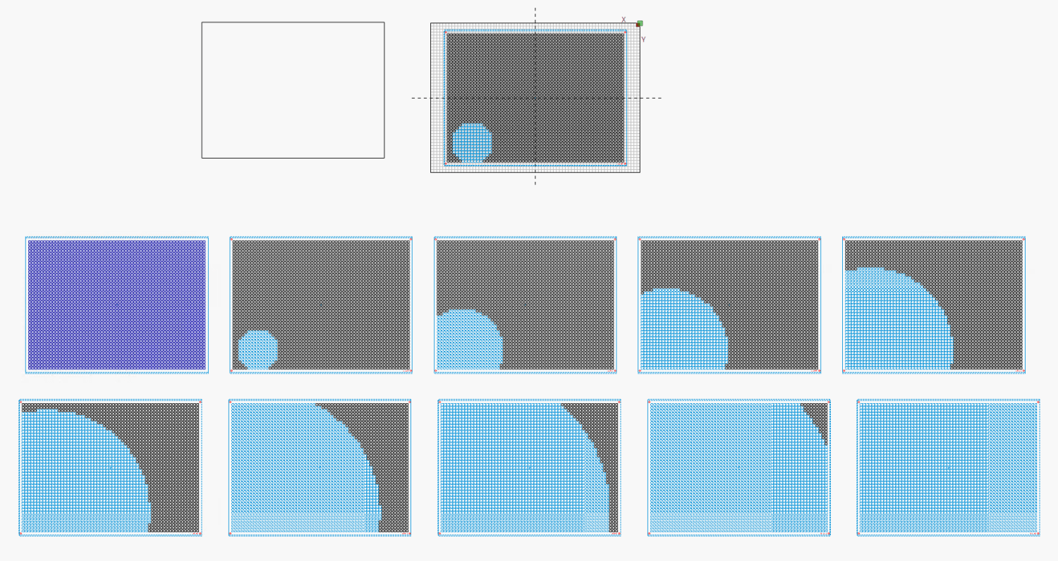
Run the program ten times to generate ten SVG images:
for i in {00..09} ; do python Layers\ -\ 24x18.py --layernum=$i --colors=9 > Test_$i.svg ; done
The LightBurn layout dwarfs the machine platform:
Layered Paper – circular colors – 24x18in – LightBurn layout
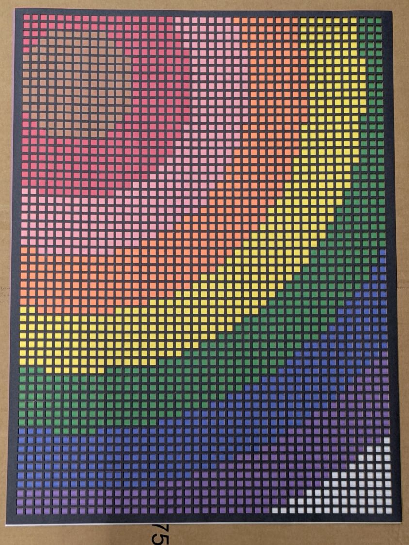
Fire The Laser ten times and you get a wall hanging:
Layered Paper – 24×18 – trial alignment
That’s a trial alignment atop a cardboard box on the Basement Shop floor, because gluing those 24×18 inch sheets of paper requires time on the Sewing Table, which is currently occupied by a much higher priority project. The brown innermost circle in the design is entirely separate from the brown Amazon cardboard box underneath everything.
Fairly obviously, you’d want something other than brown at the focal point of that design, but following the EIA color code gives me some confidence the result matches the intention. Feel free to tart it up with your own colors.
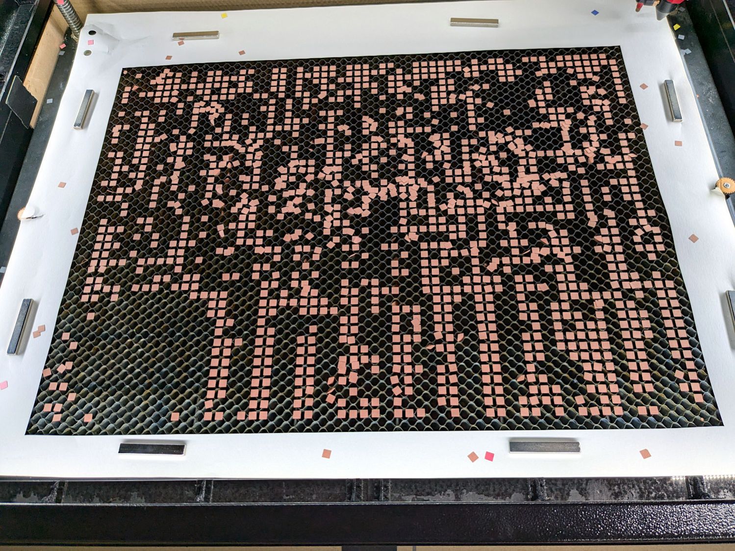
I laid a 29×23 inch sheet of sketch paper on the honeycomb, distributed neodymium bar magnets around the perimeter, and cut a 24×18 rectangle out of the middle:
Layered Paper – 24×18 – brown squares
Those squares are the cutouts from the brown sheet, minus what you see in the lead picture.
The black rectangle on the left of the LightBurn layout above is the 24×18 inch cut for the fixture. Centering that rectangle on the LightBurn layout (click-select, Ctrl-D to duplicate, then hit P to move it to the center) means aligning each of the ten patterns requires nothing more than the same click-select / dupe / P, with no delicate fiddling.
Then just lay each colored sheet into the hole and it’s properly aligned. Because the machine homes to the same physical location every time it’s turned on and the fixture is mmm fixed to the platform, cutting all ten sheets over the course of two days proceeded smoothly.
Cutting 2537 holes in the black mask takes a little under an hour:
Layered Paper – 24×18 – cutting black
The other sheets have fewer holes and go progressively faster:
Layered Paper – 24×18 – cutting yellow
The white sheet on the bottom has four alignment holes and four layer ID holes, so the cuts take a few seconds.