
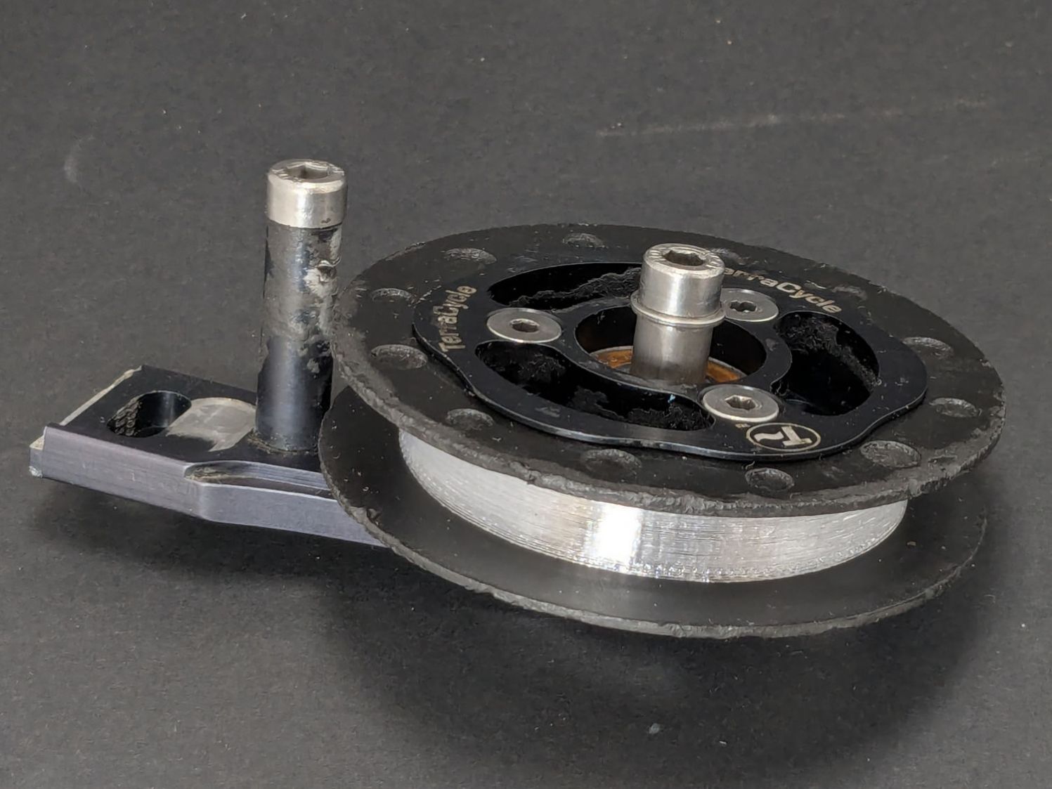
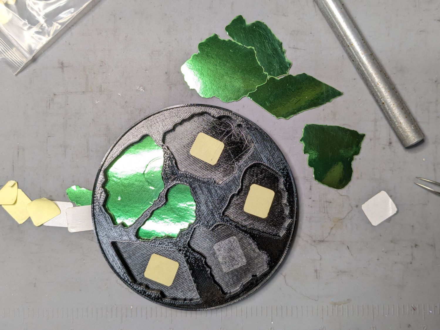
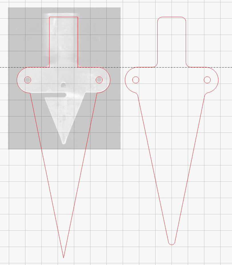
The first step in adding a filter bag to the dryer vent requires a convenient way to attach it. Because we live in the future, a couple of hours of 3D printing produced something that might work:

It’s made of TPU, which is bendy enough to ease two tabs into the two outermost slots you can see and a corresponding pair of tabs into slots on the wall side.
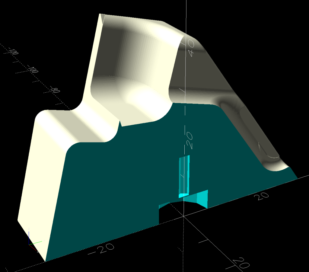
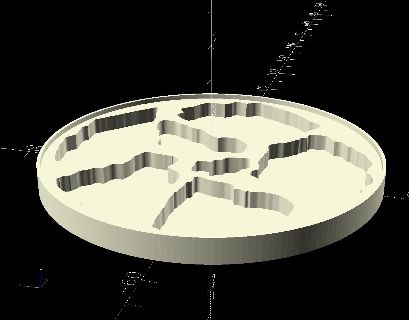
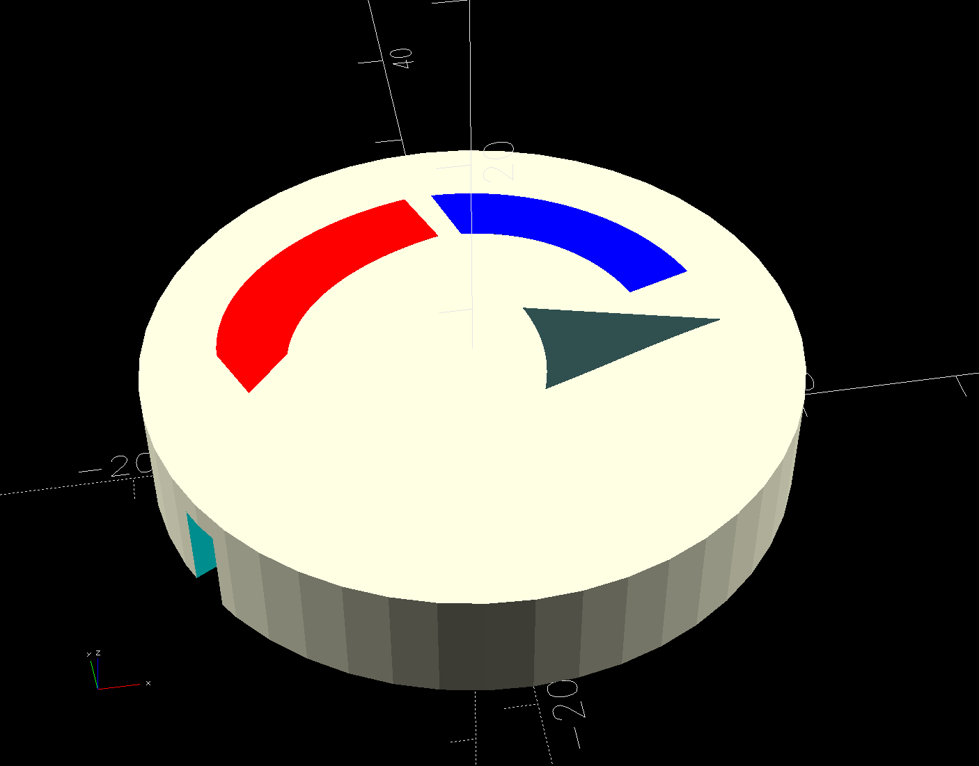
The solid model shows the part snapped inside the vent:

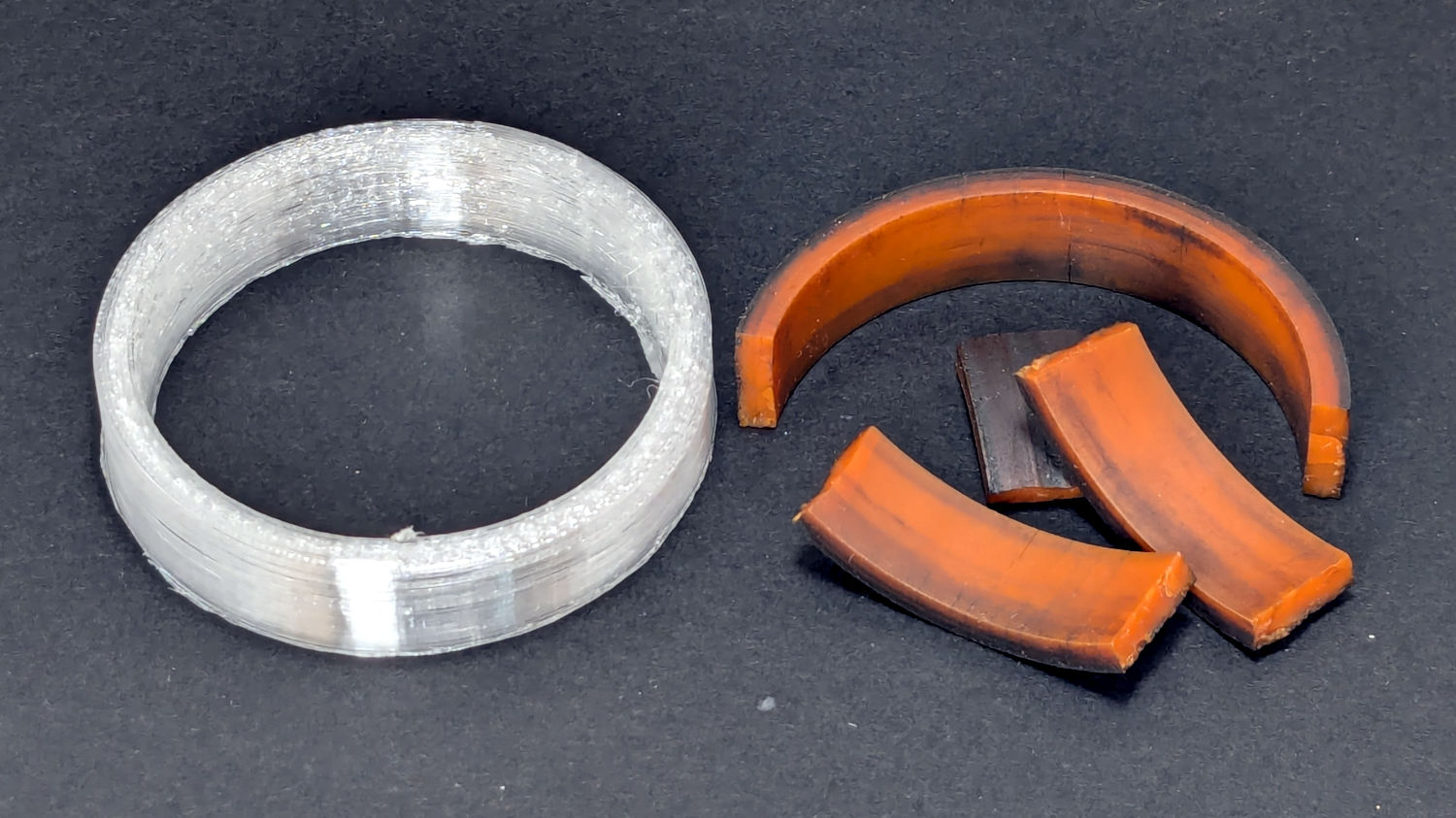
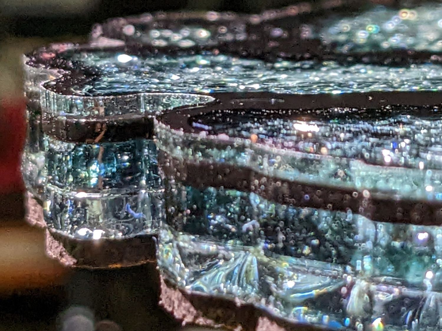
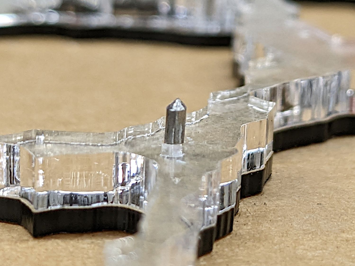
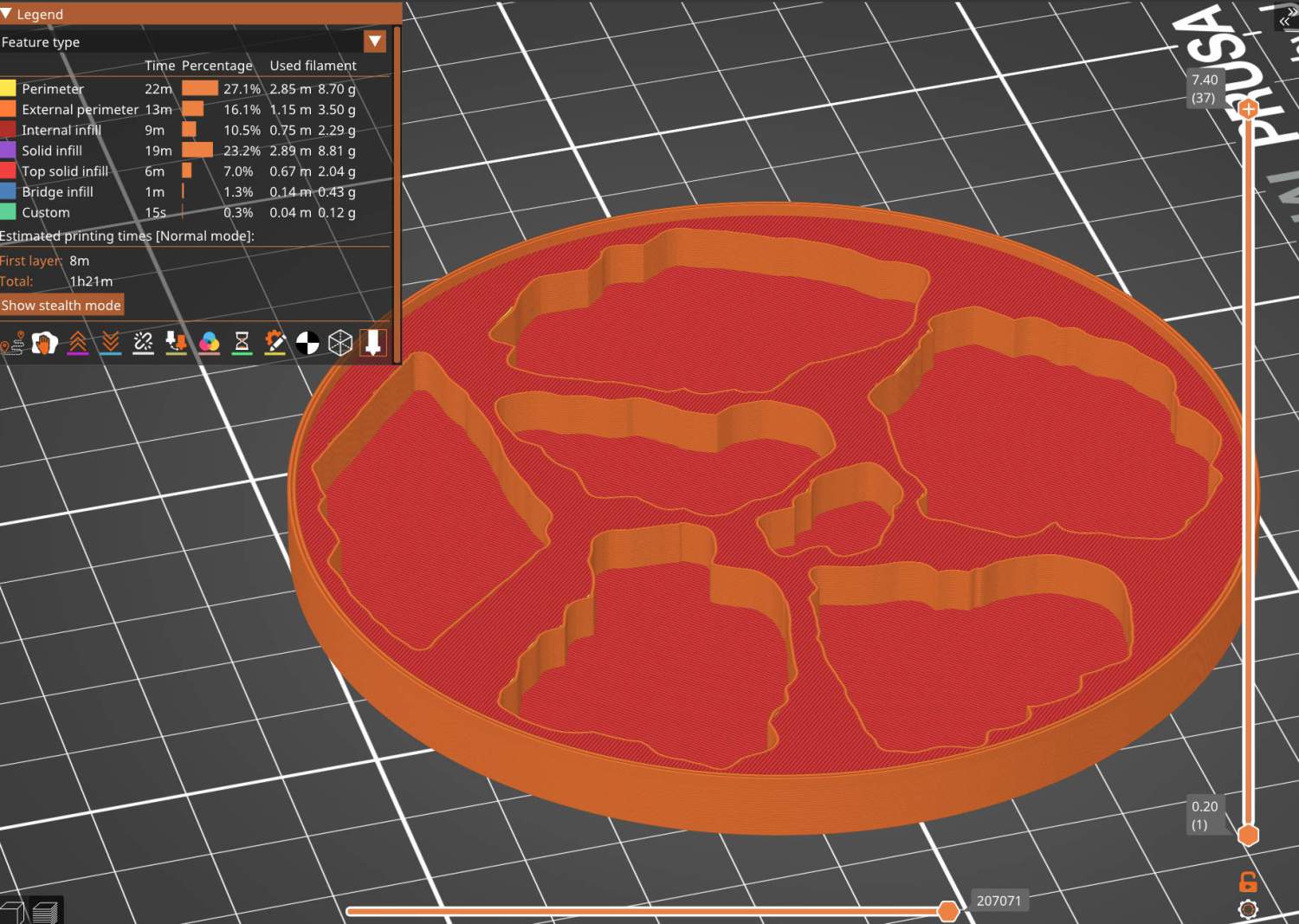
The flared bottom takes something like three hours to print (TPU likes slooow extrusion), so I did the top ring first to verify the tab fit:

Both parts come from hull() surfaces wrapped around quartets of thin circles at the proper positions; the difference() of two slightly different hulls produces thin shells.
A thin layer of JB PlasticBonder urethane adhesive, which bonds TPU like glue, holds the two parts together. I used the tan variant and, while it’s not a perfect match, it definitely looks better than black. Not that it matters in this case.
Mary will sew up a bag with a drawstring holding it to the snout. If everything survives the performance tests, printing the whole snout in one four-hour job will both make sense and eliminate an uneven joint that’s sure to be a lint-catcher.
The OpenSCAD source code as a GitHub Gist:
| // Clothes dryer vent filter snout | |
| // Ed Nisley – KE4ZNU | |
| // 2025-10-07 | |
| include <BOSL2/std.scad> | |
| Layout = "Ring"; // [Show,Build,Ring,Taper] | |
| /* [Hidden] */ | |
| ID = 0; | |
| OD = 1; | |
| LENGTH = 2; | |
| HoleWindage = 0.2; | |
| Protrusion = 0.1; | |
| NumSides = 4*3*2*4; | |
| $fn=NumSides; | |
| Gap = 5.0; | |
| // Centers of corner rounding circles | |
| InnerWidth = 3.0; // wall inside snout | |
| InnerRadius = 6.0; // inner corner rounding | |
| RR = [130.0/2 – InnerRadius,91.0/2 – InnerRadius]; // right rear corner | |
| RF = [112.0/2 – InnerRadius,-(91.0/2 – InnerRadius)]; // right front corner | |
| CornerCtrs = [[RR.x,RR.y],[RF.x,RF.y],[-RF.x,RF.y],[-RR.x,RR.y]]; // clockwise from RR | |
| InsertHeight = 7.0; // overall height inside the snout | |
| TabOC = [73.0,91.0]; // tabs locking into snout | |
| TabCtrs = [[TabOC.x/2,TabOC.y/2],[TabOC.x/2,-TabOC.y/2],[-TabOC.x/2,-TabOC.y/2],[-TabOC.x/2,TabOC.y/2]]; | |
| TabRadius = 5.0; | |
| TabHeight = 3.0; | |
| TaperHeight = 20.0; // Taper holding filter bag | |
| TaperRadius = 10.0; // outward to capture bag string | |
| TaperWidth = 2.0; // wall width | |
| TaperCtrs = CornerCtrs + [[0,-(TaperRadius – InnerWidth)],[0,0],[0,0],[0,-(TaperRadius – InnerWidth)]]; | |
| //—– | |
| // Clear inside vent opening as 2D shape | |
| module Opening() { | |
| hull() | |
| for (p = CornerCtrs) | |
| translate(p) | |
| circle(r=InnerRadius); | |
| } | |
| //—– | |
| // Insert ring locking into vent snout | |
| module Ring() { | |
| difference() { | |
| union() { | |
| linear_extrude(h=InsertHeight) | |
| offset(delta=InnerWidth) | |
| hull() | |
| for (p = CornerCtrs) | |
| translate(p) | |
| circle(r=InnerRadius); | |
| up(InsertHeight – TabHeight) | |
| linear_extrude(h=TabHeight) | |
| for (p = TabCtrs) | |
| translate(p) | |
| circle(r=TabRadius); | |
| } | |
| down(Protrusion) | |
| linear_extrude(h=2*InsertHeight) | |
| Opening(); | |
| } | |
| } | |
| //—– | |
| // Taper glued to ring | |
| module Taper() { | |
| difference() { | |
| hull() { | |
| up(TaperHeight) | |
| linear_extrude(h=Protrusion) | |
| offset(delta=InnerWidth) | |
| hull() | |
| for (p = CornerCtrs) | |
| translate(p) | |
| circle(r=InnerRadius); | |
| linear_extrude(h=Protrusion) | |
| offset(delta=TaperRadius) | |
| hull() | |
| for (p = TaperCtrs) | |
| translate(p) | |
| circle(r=TaperRadius); | |
| } | |
| hull() { | |
| up(TaperHeight) | |
| linear_extrude(h=2*Protrusion) | |
| offset(delta=InnerWidth) | |
| hull() | |
| for (p = CornerCtrs) | |
| translate(p) | |
| circle(r=InnerRadius – InnerWidth); | |
| down(Protrusion) | |
| linear_extrude(h=2*Protrusion) | |
| offset(delta=TaperRadius – TaperWidth) | |
| hull() | |
| for (p = TaperCtrs) | |
| translate(p) | |
| circle(r=TaperRadius); | |
| } | |
| } | |
| } | |
| //—– | |
| // Build things | |
| if (Layout == "Ring") | |
| Ring(); | |
| if (Layout == "Taper") | |
| Taper(); | |
| if (Layout == "Show") { | |
| up(TaperHeight) | |
| Ring(); | |
| Taper(); | |
| } | |
| if (Layout == "Build") { | |
| back(55) | |
| up(InsertHeight) | |
| yrot(180) | |
| Ring(); | |
| fwd(55) | |
| up(TaperHeight) | |
| yrot(180) | |
| Taper(); | |
| } |


